Table of Contents
Advertisement
Quick Links
Download this manual
See also:
Manual
Advertisement
Chapters
Table of Contents
Troubleshooting

Related Manuals for Mercury MerCruiser D2.8L D-Tronic


Summary of Contents for Mercury MerCruiser D2.8L D-Tronic
-
Page 1: Marine Engines
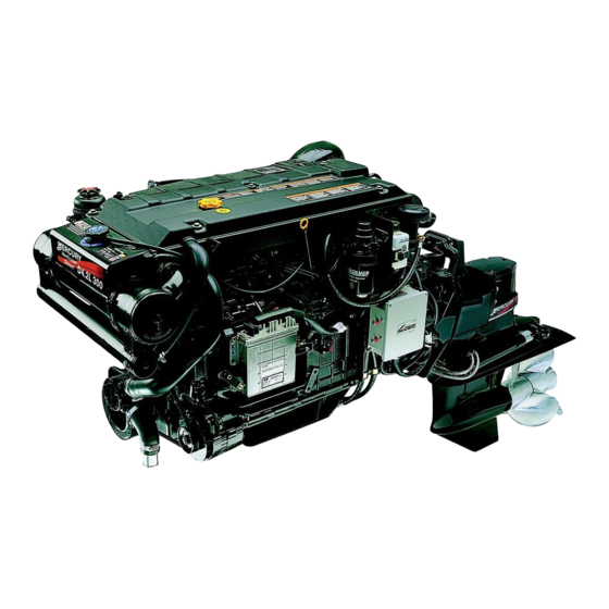
D2.8L D-Tronic ..Serial Number 0K000001 and Above D4.2L D-Tronic ..Serial Number 0K000001 and Above 2002, Mercury Marine Printed in U.S.A. 90-860074--1 FEBRUARY 2002... - Page 3 Notice Throughout this publication, Dangers, Warnings and Cautions (accompanied by the International HAZARD Symbol ) are used to alert the mechanic to special instructions concerning a particular service or operation that may be hazardous if performed incorrectly or carelessly. OBSERVE THEM CAREFULLY! These Safety Alerts alone cannot eliminate the hazards that they signal.
- Page 4 Notice to Users of This Manual This service manual has been written and published by the Service Department of Mercury Marine to aid our dealers’ mechanics and company service personnel when servicing the products described herein. It is assumed that these personnel are familiar with marine product servicing procedures.
-
Page 5: Replacement Parts
Failure to use recommended Mercury / Quicksilver service replacement parts can result in poor engine performance and/or durability, rapid corrosion of parts subjected to salt water and possibly complete failure of the engine. - Page 6 Models Covered in This Manual Sterndrive (MCM) Serial Number D2.8L D-Tronic 0K000001 and Above D4.2L D-Tronic 0K000001 and Above Inboard (MIE) Serial Number D2.8L D-Tronic 0K000001 and Above D4.2L D-Tronic 0K000001 and Above Page iv 90-860074--1 FEBRUARY 2002...
- Page 7 A - Sterndrive (MCM) Models B - Inboard (MIE) Models Engine Mechanical Section 3 - Engine Mechanical A - D2.8L D-Tronic And D4.2L D-Tronic Engines Section 4 - Electrical System A - Starting System Electrical System B - Charging System...
- Page 8 1A-6 Page Numbering ....1A-3 Mercury/Quicksilver Lubricants, Sealants Engine Serial Number / Decal Locations 1A-4 And Adhesives ..... . .
- Page 9 IMPORTANT INFORMATION SECTION 1C - Troubleshooting Precautions ......1C-3 Turbocharger ......1C-18 Poor Boat Performance and/or Poor Engine Noise...
- Page 10 ENGINE Section 3A - Engine Mechanical Identification ......3A-3 Installation ......3A-34 Torque Specifications .
- Page 11 ENGINE (continued) Section 3A - Engine Mechanical (continued) Adapter / Oil Thermostat ....3A-91 Cleaning ......3A-109 Removal .
- Page 12 ELECTRICAL SYSTEMS Section 4B - Charging System Identification ......4B-3 Circuitry Test ......4B-10 Replacement Parts Warning .
-
Page 13: Section 5A - Description
ELECTRICAL SYSTEMS Section 4E - Wiring Diagrams Wire Color Abbreviations ....4E-3 MerCathode System Wiring Diagram 4E-15 Tools ....... . 4E-3 Inboard (MIE) Models . -
Page 14: Fuel System
FUEL SYSTEM Section 5C - Fuel Injectors Identification ......5C-3 Exploded View ......5C-8 Specifications . -
Page 15: Section 5E - Edi Diagnosis
FUEL SYSTEM Section 5E - EDI Diagnosis General Information ....5E-2 Main Relay ..... . . 5E-46 Introduction . -
Page 16: Section 6A - Seawater Cooling System
....6A-33 D2.8L D-Tronic ..... - Page 17 INTAKE AND EXHAUST SYSTEM Section 7A - Intercooler Torque Specifications ....7A-3 Removal ......7A-8 Lubricants / Sealants / Adhesives .
- Page 18 DRIVES Section 8A - ZF/Hurth Transmissions Identification ......8A-3 Transmission Fluid Level ....8A-8 Specifications .
- Page 19 THIS PAGE IS INTENTIONALLY BLANK 90-860074--1 FEBRUARY 2002 Page xvii...
- Page 20 THIS PAGE IS INTENTIONALLY BLANK Page xviii 90-860074--1 FEBRUARY 2002...
-
Page 21: Table Of Contents
1A-6 Page Numbering ....1A-3 Mercury/Quicksilver Lubricants, Sealants Engine Serial Number / Decal Locations 1A-4 And Adhesives ..... . . - Page 22 GENERAL INFORMATION SERVICE MANUAL NUMBER 22 THIS PAGE IS INTENTIONALLY BLANK Page 1A-2 90-860064--1 FEBRUARY 2002...
-
Page 23: Introduction
GENERAL INFORMATION SERVICE MANUAL NUMBER 22 NOTICE For information and procedures on Troubleshooting, refer to SECTION 1C. NOTICE Refer to appropriate Sterndrive Service Manual for transom assembly and sterndrive unit repair. Introduction This comprehensive overhaul and repair manual is designed as a service guide for the models previously listed. -
Page 24: Engine Serial Number / Decal Locations
GENERAL INFORMATION SERVICE MANUAL NUMBER 22 Engine Serial Number / Decal Locations 71675 75301 7332 73929 75388 SERIAL NUMBER 75298 MARINE POWER M12 11 3 EUROPE INC 93_ _ MADE IN ITALY 71688 Typical Sterndrive (MCM) Engine Shown - Inboard (MIE) Similar Serial Number Plate Manufacturer’s Serial Number (Stamped in Block) Exhaust Gas Emissions Certificate Number (Example) -
Page 25: Operation / Duty Cycle
IMPORTANT: Damage caused by improper application or failure to operate within the operational capability, or duty cycle, will not be covered by the Mercury MerCruiser Diesel Limited Warranty. PLEASURE DUTY RATING / DUTY CYCLE D2.8L D-Tronic and D4.2L D-Tronic... -
Page 26: Engine Break-In
GENERAL INFORMATION SERVICE MANUAL NUMBER 22 Engine Break-In Initial Break-In Procedure The following procedure must be used on new and rebuilt diesel engines. This break-in procedure allows the proper seating of the pistons and rings, which greatly reduces the likelihood of problems. IMPORTANT: It is recommended that the boat not be accelerated hard until this procedure has been completed. -
Page 27: Mercury/Quicksilver Lubricants, Sealants And Adhesives
GENERAL INFORMATION SERVICE MANUAL NUMBER 22 Mercury/Quicksilver Lubricants, Sealants And Adhesives Mercury Part Quicksilver Part Tube Description Container Size Number Number Ref. # Needle Bearing Assy. 8 oz (226.8 g) tube 92-802868A1 Lubricant Dielectric Grease 8 oz (226.8 g) can... - Page 28 GENERAL INFORMATION SERVICE MANUAL NUMBER 22 Mercury Part Quicksilver Part Tube Description Container Size Number Number Ref. # Premium Plus 2 Cycle 1 US qt (0.94 L) 92-802824A1 92-802824Q1 TC-W3 Outboard Oil RTV 587 Silicone 3 oz (85.05 g) 92-809825...
- Page 29 GENERAL INFORMATION SERVICE MANUAL NUMBER 22 THIS PAGE IS INTENTIONALLY BLANK 90-860074-–1 FEBRUARY 2002 Page 1A-9...
- Page 30 GENERAL INFORMATION SERVICE MANUAL NUMBER 22 THIS PAGE IS INTENTIONALLY BLANK Page 1A-10 90-860064--1 FEBRUARY 2002...
- Page 31 MAINTENANCE SERVICE MANUAL NUMBER 22 IMPORTANT INFORMATION Section 1B - Maintenance Table of Contents Torque Specifications ....1B-3 Throttle Cable ..... 1B-39 Special Tools .
- Page 32 MAINTENANCE SERVICE MANUAL NUMBER 22 THIS PAGE IS INTENTIONALLY BLANK Page 1B-2 90-860074--1 FEBRUARY 2002...
-
Page 33: Torque Specifications
Water Tap Hose Adapter To Water Inlet Fitting Obtain Locally Typical Hand-operated Grease Gun Lubricants / Sealants / Adhesives Description Part Number Mercury Diesel Engine Oil 92-877695K1 Liquid Neoprene 92-25711--3 Loctite 567 PST Pipe Sealant 92-809822 Engine Coupler Spline Grease... -
Page 34: Engine Specifications
28-83). Refer to Conditions Affecting Operation - Propeller Selection for additional information. Mercury Serial Number 0L343084 and Below on D2.8L D-Tronic Engines. Mercury Serial Number 0L343703 and Below on D4.2L D-Tronic Engines. Mercury Serial Number 0L343085 and Above on D2.8L D-Tronic Engines. Mercury Serial Number 0L343704 and Above on D4.2L D-Tronic Engines. -
Page 35: Inboard (Mie) Engines
28-83). Refer to “Conditions Affecting Operation - Propeller Selection” for additional information. Mercury Serial Number 0L343084 and Below on D2.8L D-Tronic Engines. Mercury Serial Number 0L343703 and Below on D4.2L D-Tronic Engines. Mercury Serial Number 0L343085 and Above on D2.8L D-Tronic Engines. Mercury Serial Number 0L343704 and Above on D4.2L D-Tronic Engines. -
Page 36: Capacities
MAINTENANCE SERVICE MANUAL NUMBER 22 Capacities NOTICE All capacities are approximate fluid measures. Engines NOTICE Unit Of Measurement: Liters (U.S. Quarts). D2.8L D4.2L Model D-Tronic D-Tronic Total Oil Capacity 10 ( 8-1/2 ) 12 ( 12-3/4 ) Oil Pan 8 ( 6-1/2 ) 10 ( 10-3/4 ) Oil Filter 1 ( 1 ) -
Page 37: Maintenance Schedules
NOTICE For information and procedures on Troubleshooting refer to SECTION 1C. Maintenance Schedules NOTE: Refer to appropriate Mercury MerCruiser Sterndrive Service Manual for information and procedures on sterndrive maintenance. WARNING Avoid injury or death, product damage, fire or explosion. The electrical system is capable of violent and damaging short circuits or severe electrical shocks. -
Page 38: Sterndrive (Mcm) Engines
MAINTENANCE SERVICE MANUAL NUMBER 22 Sterndrive (MCM) Engines Routine Maintenance * Each Each Every Weekly Start Months Check crankcase oil (interval can be extended based on experi- ence). If operating in salt, brackish or polluted waters, flush cooling sys- tem after each use. Drain any water from fuel filter after each use (If operating in freez- ing temperatures). - Page 39 MAINTENANCE SERVICE MANUAL NUMBER 22 Sterndrive (MCM) Engines (Continued) Scheduled Maintenance * Every Every Every Every Every 1000 After Every Every hours hours hours hours First Annu- hours or ally or 3 or 3 or 5 or 5 Annually years years hours years...
- Page 40 MAINTENANCE SERVICE MANUAL NUMBER 22 Sterndrive (MCM) Engines (Continued) Scheduled Maintenance * (Continued) Every Every Every Every Every 1000 After Every Every hours hours hours hours First Annu- hours or ally or 3 or 3 or 5 or 5 Annually years years hours...
-
Page 41: Inboard (Mie) Engines
MAINTENANCE SERVICE MANUAL NUMBER 22 Inboard (MIE) Engines Routine Maintenance * Each Each Every Weekly Start Months Check crankcase oil (interval can be extended based on experi- ence). If operating in salt, brackish or polluted waters, flush cooling sys- tem after each use. Drain any water from fuel filter after each use (if operating in freezing temperatures). - Page 42 MAINTENANCE SERVICE MANUAL NUMBER 22 Inboard (MIE) Engines (Continued) Scheduled Maintenance * Every Every Every Every 1000 After Every hours hours hours First Annu- hours or ally or 3 or 5 or 5 Annually years hours years years years Change crankcase oil and filter. Touch-up paint power package and spray with corrosion guard.
-
Page 43: Engine External Views
MAINTENANCE SERVICE MANUAL NUMBER 22 Engine External Views Starboard Side View 78409 Typical In-Line D-Tronic Diesel Exhaust Riser, or Elbow If Equipped Intercooler Air Duct Fluid Cooler Shift Plate Intercooler Sacrificial Anode Power Steering Fluid Reservoir Thermostat Housing Heat Exchanger 10 - Engine Oil Cooler 11 -... -
Page 44: Front View
MAINTENANCE SERVICE MANUAL NUMBER 22 Front View 78310 Typical In-Line D-Tronic Diesel Sacrificial Anode Pressure Cap Heat Exchanger Engine Oil Cooler Seawater Pump Outlet Hose Alternator Seawater Pump Inlet Hose Seawater Pump Oil Pan 10 - Crankshaft Pulley 11 - Engine Water Circulating Pump Pulley 12 - Power Steering Pump... -
Page 45: Port Side View
MAINTENANCE SERVICE MANUAL NUMBER 22 Port Side View 75298 Typical In-Line D-Tronic Diesel Oil Fill Cap Engine Cover Fuel Injector Fuel Filter Gear Lube Monitor PCV / Oil Separator Air Filter MerCathode Controller Rear Engine Mount 10 - Flywheel Housing (Rear Portion) 11 - 5 Amp. -
Page 46: Rear View
MAINTENANCE SERVICE MANUAL NUMBER 22 Rear View 74305 Typical In-Line D-Tronic Diesel Air Filter Turbocharger Exhaust Elbow Rear Engine Mount Engine Coupler Flywheel Housing (Rear Portion) Electrical Box Page 1B-16 90-860074--1 FEBRUARY 2002... -
Page 47: Engine Oil
VEEDOL TURBOSTAR MOPAR WINTERSHALL MULTI-REKORD WINTERSHALL VIVA 1 These oils are approved by Mercury Marine and Marine Power Europe. For all temperature operation use 15W-40 oil. Oil Level OVERFILLED ENGINE CRANKCASE An overfilled crankcase can cause a fluctuation or drop in oil pressure on Mercury MerCruiser engines. - Page 48 MAINTENANCE SERVICE MANUAL NUMBER 22 CHECKING / FILLING IMPORTANT: Engine crankcase oil must be checked at intervals specified in Maintenance Schedule. It is normal for an engine to use a certain amount of oil in the process of lubricating and cooling the engine. The amount of oil consumed is greatly dependent upon engine speed, with consumption being highest at WOT and decreasing substantially as engine speed is reduced.
-
Page 49: Changing Engine Oil And Oil Filter
MAINTENANCE SERVICE MANUAL NUMBER 22 Changing Engine Oil and Oil Filter IMPORTANT: Change oil when engine is warm from operation. Warm oil flows more freely, carrying away more impurities. Use only recommended engine oil (see Specifications). 1. Start engine and allow it to reach normal operating temperature. 2. - Page 50 MAINTENANCE SERVICE MANUAL NUMBER 22 8. Remove and discard oil filter and seal. 9. Coat seal on new filter with engine oil and install filter. Hand tighten only, do NOT use a filter wrench. 75297 Oil Filter Seal 10. Remove oil fill cap and refill engine with new engine oil. CAUTION Do NOT overfill the engine with oil.
-
Page 51: Fuel
MAINTENANCE SERVICE MANUAL NUMBER 22 Fuel Precautions WARNING Always disconnect battery cables from battery BEFORE working on fuel system to prevent fire. This eliminates the engine wiring as a potential source of ignition. WARNING FIRE HAZARD: Fuel leakage from any part of the fuel system can be a fire hazard which can cause serious bodily injury or death. -
Page 52: General Information
CAUTION Avoid fuel system damage. Use of fuels not recommended by Mercury MerCruiser may cause hard-starting and other various troubles such as premature wear of the injection pump plungers and injection nozzles resulting from the deposit of carbon residue and other contaminants. -
Page 53: Fuel Filter
MAINTENANCE SERVICE MANUAL NUMBER 22 Fuel Filter PRECAUTIONS WARNING Be careful when draining, filling or replacing water separating fuel filter; diesel fuel is flammable. Ensure that the ignition key is OFF. Do NOT smoke or allow sources of open flame in the area while changing fuel system components. Wipe up any spilled fuel immediately. - Page 54 MAINTENANCE SERVICE MANUAL NUMBER 22 DRAINING NOTICE Refer to Precautions BEFORE proceeding. The filter can be drained of water and small dirt particles by opening the water drain cap (bleed valve). IMPORTANT: To ensure complete draining, in warm weather, open the drain cock before starting daily operations.
- Page 55 MAINTENANCE SERVICE MANUAL NUMBER 22 FILLING NOTICE Refer to Precautions BEFORE proceeding. Follow this procedure after installing a new filter or if fuel has been completely drained from the filter checking for water. NOTE: Place a suitable container under fuel filter to catch contaminated fuel and/or water 1.
- Page 56 MAINTENANCE SERVICE MANUAL NUMBER 22 REMOVAL NOTICE Refer to Precautions BEFORE proceeding. NOTE: Place a suitable container under fuel filter to catch contaminated fuel and/or water 1. Twist locking ring by hand. Remove water separating fuel filter and sealing ring from mounting bracket.
- Page 57 MAINTENANCE SERVICE MANUAL NUMBER 22 INSTALLATION 1. Install O-ring and drain cap on new filter. 70160 O-ring Seal Drain Cap 2. Lubricate seal with clean engine oil. 3. Align filter to bracket. Twist locking ring by hand to secure filter to bracket. Do NOT use a filter wrench.
-
Page 58: Closed Cooling System
MAINTENANCE SERVICE MANUAL NUMBER 22 Closed Cooling System Coolant Requirement CAUTION Alcohol or methanol based anti-freeze or plain water are not recommended for use in the closed cooling section of cooling system at any time. Because diesel engines are high compression engines and related higher engine operating temperatures are created, the closed cooling system and engine must remain as clean as possible to provide adequate engine cooling. -
Page 59: Checking Level
MAINTENANCE SERVICE MANUAL NUMBER 22 Checking Level 1. Coolant level must be between the bottom ADD mark and top FULL Hot mark on coolant recovery bottle with the engine at normal operating temperature. 72520 Coolant Recovery Reservoir Bottom ADD Mark Top FULL Hot Mark 2. -
Page 60: Draining
MAINTENANCE SERVICE MANUAL NUMBER 22 Draining NOTICE For instructions on Draining Seawater Section refer to Cold Weather or Extended Storage in this SECTION 1B. IMPORTANT: Observe the following: Insert a wire into drain holes to ensure that foreign material is not obstructing the drain holes. - Page 61 MAINTENANCE SERVICE MANUAL NUMBER 22 3. –Drain coolant from the engine block by opening the drain valve. 76391 Typical Engine Block Drain Valve 4. After coolant has drained completely, securely close drain valves. 5. Empty the coolant recovery bottle. 6. If required, clean the closed cooled system. Refer to SECTION 6A. 7.
-
Page 62: Filling
MAINTENANCE SERVICE MANUAL NUMBER 22 Filling 1. Slowly fill with coolant through heat exchanger fill neck. 2. Continue filling until coolant level is at bottom of fill neck. CAUTION Overheating from insufficient cooling water will cause engine and drive system damage. -
Page 63: Sacrificial Anodes
MAINTENANCE SERVICE MANUAL NUMBER 22 Sacrificial Anodes Sacrificial anode locations: • Starboard, aft-side of the heat exchanger. • Top of the intercooler end cover. Removal 1. Allow the engine to cool. 2. Remove anode plugs and sacrificial anodes. 73326 73327 Heat Exchanger Intercooler End Cover Anode Plug And Sacrificial Anode... -
Page 64: Disassembly
MAINTENANCE SERVICE MANUAL NUMBER 22 Disassembly NOTE: Sacrificial anodes are available as an assembly. Replace both the plug and anode, if so desired. 1. Unscrew sacrificial anode from anode plug by holding plug hex head and turning anode. 71367 Plug Anode Reassembly 1. -
Page 65: Flushing Seawater System
MAINTENANCE SERVICE MANUAL NUMBER 22 Flushing Seawater System If engine is operated in salty, polluted or mineral-laden water, flush seawater section of cooling system (preferably after each use) to reduce corrosion and prevent the accumulation of deposits in the system. Thoroughly flush seawater section prior to storage. SternDrive (MCM) Models WARNING When flushing, be certain the area around propeller is clear and no one is standing... -
Page 66: Inboard (Mie) Models
MAINTENANCE SERVICE MANUAL NUMBER 22 Inboard (MIE) Models WARNING When flushing, be certain the area around propeller is clear, and no one is standing nearby. To avoid possible injury, remove propeller. CAUTION If boat is in the water, seacock (water inlet valve), if equipped, must be closed until engine is to be re-started, to prevent water from flowing into the boat and/or back into the cooling system. - Page 67 MAINTENANCE SERVICE MANUAL NUMBER 22 3. Using an adapter, connect a hose between the water inlet hose or connector fitting and a water tap. 75299 Inlet Hose Adapter Hose To Water Tap 4. Partially open the water tap, approximately 1/2 maximum capacity. Do NOT use full water pressure.
-
Page 68: Inspect Water Pickups
MAINTENANCE SERVICE MANUAL NUMBER 22 Inspect Water Pickups SternDrive Gear Housing 1. Ensure that the gear housing water inlet holes are clean and not obstructed. 73186 Typical Water Inlet Holes Inboard Though the Hull Pickup 1. Ensure that the seawater pickup water inlet holes (slots) are clean and not obstructed. 70355 Typical Water Inlet Holes (Slots) -
Page 69: Lubrication
MAINTENANCE SERVICE MANUAL NUMBER 22 Lubrication Throttle Cable 1. Lubricate pivot points and guide contact surfaces with SAE 30W engine oil. 75332 Single Cable Shown (Dual Similar) Pivot Points Guide Contact Surfaces Shift Cable 1. Lubricate pivot points and guide contact surfaces with SAE 30W engine oil. 22245 73587 Typical Sterndrive Model Shift Cable... -
Page 70: Engine Coupler / U-Joint Shaft Splines 1B-40
SERVICE MANUAL NUMBER 22 Engine Coupler / U-joint Shaft Splines NOTE: Refer to the appropriate Mercury MerCruiser Sterndrive Service Manual for sterndrive unit removal and installation, if necessary. IMPORTANT: These engines are equipped with a sealed engine coupler. The sealed coupler and the shaft splines can be lubricated without removing the sterndrive unit. -
Page 71: U-Joints
The sterndrive unit must be removed to grease these fittings. 1. Remove the sterndrive unit; refer to the appropriate Mercury MerCruiser Sterndrive Service Manual for sterndrive unit removal and installation. 2. Apply U-joint And Gimbal Bearing Grease (Except on Bravo X Drives - use Exxon Unirex EP2 Grease [Obtain Locally] ) from a typical hand-operated grease gun until a small amount of grease begins to push out. -
Page 72: Drive Shaft Extension Models
MAINTENANCE SERVICE MANUAL NUMBER 22 Drive Shaft Extension Models 1. Apply 3-4 pumps of U-joint And Gimbal Bearing Grease to drive shaft grease fittings. 71347 71346 Transom End Fittings Engine End Fittings Sterndrive Unit and Transom Assembly 1. Apply approximately 8-10 pumps of U-joint And Gimbal Bearing Grease to the gimbal bearing. -
Page 73: Continuity Circuit
MAINTENANCE SERVICE MANUAL NUMBER 22 Continuity Circuit The transom assembly and the sterndrive unit are equipped with ground circuit wires to ensure good electrical continuity between the engine, the transom assembly and the sterndrive components. Good continuity is essential for the Anode and the MerCathode System to function most effectively. -
Page 74: Continuity Circuit (Continued)
MAINTENANCE SERVICE MANUAL NUMBER 22 Continuity Circuit (continued) 22028 Flywheel Housing Grounding Stud Ground Wire Inner Transom Plate Grounding Screw 22755 22031 Gimbal Ring To Bell Housing Ground Wire Sterndrive Unit To Bell Housing Ground Plate 70575 22230 Driveshaft Housing To Gear Housing Anodic Plate Hydraulic Connector Block To Gimbal Housing Ground Washer 22079 50383... -
Page 75: Mercathode
The test should be made where the boat is moored, using Quicksilver Reference Electrode and Test Meter. Refer to the appropriate Mercury MerCruiser Sterndrive Service Manual for testing procedures. Engine Mounts 1. -
Page 76: Power Steering
MAINTENANCE SERVICE MANUAL NUMBER 22 Power Steering Checking Fluid Level IMPORTANT: Use only Power Trim and Steering Fluid or automatic transmission fluid (ATF) Dexron III in power steering system. ENGINE WARM 1. Stop engine and center the sterndrive unit. 2. Remove the dipstick from the power steering fluid reservoir and observe the fluid level. 3. - Page 77 MAINTENANCE SERVICE MANUAL NUMBER 22 ENGINE COLD 1. With engine stopped, center sterndrive unit. 2. Remove dipstick from power steering fluid reservoir and observe fluid level. 3. The level should be between the full cold mark and the bottom of the dipstick. 23162 73326 Dipstick...
-
Page 78: Filling And Bleeding
MAINTENANCE SERVICE MANUAL NUMBER 22 Filling and Bleeding 1. With engine stopped, center sterndrive unit. 2. Remove dipstick from power steering reservoir. IMPORTANT: Use only Power Trim and Steering Fluid or Dexron III automatic transmission fluid (ATF) in power steering system. 3. -
Page 79: Transmission
MAINTENANCE SERVICE MANUAL NUMBER 22 Transmission Checking Fluid Level IMPORTANT: To accurately check fluid level, the engine must be operated at 1500 rpm for 2 minutes immediately prior to checking level. 1. Start engine and run at 1500 rpm for 2 minutes to fill all circuits, lines, and cooler. 2. -
Page 80: Power Trim
MAINTENANCE SERVICE MANUAL NUMBER 22 Power Trim Checking Fluid Level 1. Place sterndrive unit in full DOWN/IN position. IMPORTANT: Some trim pump reservoir fill caps have a small vent hole. Occasionally ensure vent is not restricted. 2. Unscrew reservoir cap. 3. -
Page 81: Filling
MAINTENANCE SERVICE MANUAL NUMBER 22 Filling 1. Add Power Trim and Steering Fluid or SAE 10W-30 engine oil to bring oil to proper level. 2. Install reservoir cap. 77348 Reservoir Fill Neck Reservoir Cap 90-860074--1 FEBRUARY 2002 Page 1B-51... -
Page 82: Gear Lube Monitor
MAINTENANCE SERVICE MANUAL NUMBER 22 Gear Lube Monitor Checking Fluid Level NOTE: Fluid level in gear lube monitor will fluctuate during operation. Level should be checked with engine cold. 1. Check for water at bottom of monitor, or milky-tan appearance. Both conditions indicate a water leak somewhere in the sterndrive unit. -
Page 83: Seawater Strainer
MAINTENANCE SERVICE MANUAL NUMBER 22 Seawater Strainer 1. Visually inspect seawater strainer through glass top. CAUTION When cleaning seawater strainer, close seacock, if equipped. If boat is not equipped with a seacock, remove and plug seawater inlet hose to prevent a siphoning action that may occur, allowing seawater to flow from the drain holes or removed hoses. -
Page 84: Air Filter
MAINTENANCE SERVICE MANUAL NUMBER 22 Air Filter Removal 1. Disconnect crankcase vent hose from end of air intake screen housing mounted on turbocharger inlet. 73323 Typical Intake Screen Housing Crankcase Vent Hose 2. Carefully remove air cleaner foam element from around air intake screen housing. 71267 Screen Housing Air Cleaner Element... -
Page 85: Cleaning
MAINTENANCE SERVICE MANUAL NUMBER 22 Cleaning 1. Wash air cleaner element in warm water and detergent until clean. IMPORTANT: No treatment (such as partial oil saturation) is required or recommended on air cleaner foam element prior to use. Use element clean and dry for proper filtration. -
Page 86: Drive Belts
MAINTENANCE SERVICE MANUAL NUMBER 22 Drive Belts General Information Belt and pulley replacement guidelines: • During belt assembly, do NOT force belt into pulley grooves by prying with a screwdriver, pry bar or similar. This will damage belt side cords, which will cause belt to turn over in pulley grooves, and result in complete destruction of belt. -
Page 87: Inspection
MAINTENANCE SERVICE MANUAL NUMBER 22 Inspection WARNING Avoid possible serious injury. Ensure engine is shut off and ignition key is removed before inspecting belts. 1. Visually inspect all drive belts for cracks, glazing, fraying or separation. 2. Check drive belts for proper tension by pressing midpoint between the pulleys on the longest belt span. -
Page 88: Alternator Belt
MAINTENANCE SERVICE MANUAL NUMBER 22 Alternator Belt NOTE: On some engines it may be necessary to remove other drive belts to gain access to a particular belt during replacement. Refer to appropriate sections for information concerning individual drive belts and proceed accordingly. CAUTION Before removing the seawater pump hoses, close the seacock, if equipped. - Page 89 MAINTENANCE SERVICE MANUAL NUMBER 22 7. Pivot the alternator. Adjust belt deflection to be 5 mm (3/16 in.) measured at midpoint between the pulleys on the longest belt span. 8. Torque tensioning and mounting bolts 28 Nm (21 lb-ft). 74301 73521 Typical Deflection: 5 mm (3/16 in.)
-
Page 90: Power Steering Pump Belt
MAINTENANCE SERVICE MANUAL NUMBER 22 Power Steering Pump Belt NOTE: On some engines it may be necessary to remove other drive belts to gain access to a particular belt during replacement. Refer to appropriate sections for information concerning individual drive belts and proceed accordingly. 1. - Page 91 MAINTENANCE SERVICE MANUAL NUMBER 22 4. Remove old belt. 5. Install new belt. 6. Pivot the power steering pump. Adjust belt deflection to be 5 mm (3/16 in.) measured at midpoint between the pulleys on the longest belt span. 7. Torque tensioning and mounting bolts to 21 Nm (15 lb-ft). 70113 73521 Mounting Bolts (1 Not Shown)
-
Page 92: Vacuum Pump Belt
MAINTENANCE SERVICE MANUAL NUMBER 22 Vacuum Pump Belt NOTE: On some engines it may be necessary to remove other drive belts to gain access to a particular belt during replacement. Refer to appropriate sections for information concerning individual drive belts and proceed accordingly. 1. - Page 93 MAINTENANCE SERVICE MANUAL NUMBER 22 6. Pivot the vacuum pump. Adjust belt deflection to be 5 mm (3/16 in.) measured at midpoint between the pulleys on the longest belt span. 7. Torque tensioning and mounting bolts to 21 Nm (15 lb-ft). 74085 Mounting Bolt Tensioning Bolt...
-
Page 94: Battery
2. To maintain a protective coating on all metal surface areas, spray with Corrosion Guard. NOTICE For additional information on sterndrive unit corrosion protection and external corrosion protection refer to appropriate Mercury MerCruiser Sterndrive Service Manual. Saltwater Operation Seawater section must be flushed after each saltwater use. Refer to SECTION 1B Flushing Seawater System. -
Page 95: Freezing Temperature And Cold Weather Operation
MAINTENANCE SERVICE MANUAL NUMBER 22 Freezing Temperature and Cold Weather Operation IMPORTANT: If boat is operated during periods of freezing temperature, precautions must be taken to prevent freeze damage to power package. Refer to the following and to Cold Weather or Extended Storage for related information and draining instructions. -
Page 96: Cold Weather Or Extended Storage
Cold Weather or Extended Storage Power Package Layup IMPORTANT: Mercury MerCruiser strongly recommends that this service be performed by an Authorized Mercury MerCruiser Dealer. Damage caused by freezing IS NOT covered by the Mercury MerCruiser Limited Warranty. CAUTION The engine must be prepared for long storage periods to prevent internal corrosion and severe damage. -
Page 97: Draining
MAINTENANCE SERVICE MANUAL NUMBER 22 Draining IMPORTANT: Drain only the seawater section of the cooling system. Closed cooling section must be kept filled year-round with specified coolant. 1. Ensure that the engine is as level as possible to promote complete draining of the cooling system. - Page 98 MAINTENANCE SERVICE MANUAL NUMBER 22 4. Remove the end covers from BOTH port and starboard ends on upper and lower sections of heat exchanger tank. 5. Drain tank completely. 6. Sponge out or soak up any water that remains in the bottom part of upper and lower heat exchanger sections, until all water passage tubes are completely free of standing water.
- Page 99 MAINTENANCE SERVICE MANUAL NUMBER 22 8. On Inboard (MIE) Engines: Disconnect seawater outlet hose at aft end of transmission fluid cooler. Lower hose and drain completely. 73335 Typical Transmission Fluid Cooler Seawater Hose 9. Remove the drain plug from the aft end cover of the intercooler. 74303 Drain Plug Intercooler...
- Page 100 MAINTENANCE SERVICE MANUAL NUMBER 22 12. Sterndrive (MCM) Only: Insert a small wire (repeatedly) to make sure that speedometer pitot tube, trim tab/anode cavity vent hole and trim tab/anode cavity drain passage are unobstructed and drained. 71217 Typical Bravo Drive Unit Speedometer Pitot Tube Vent Hole Drain Passage...
- Page 101 MAINTENANCE SERVICE MANUAL NUMBER 22 IMPORTANT: Mercury MerCruiser recommends that propylene glycol antifreeze (nontoxic and biodegradable, which makes it friendly to lakes and rivers) be used in seawater section of the cooling system for cold weather or extended storage. Make sure that the propylene glycol antifreeze contains a rust inhibitor and is recommended for use in marine engines.
- Page 102 MAINTENANCE SERVICE MANUAL NUMBER 22 23. Remove seawater pump impeller for storage: a. Remove seawater pump cover mounting screws, and remove cover and gasket. b. Ease impeller off pump shaft with two screwdrivers. c. Reinstall cover for storage. NOTE: Pump shown removed for visual clarity only. 71366 Typical Seawater Pump Housing...
-
Page 103: Recommissioning
MAINTENANCE SERVICE MANUAL NUMBER 22 Recommissioning NOTICE Refer to Cold Weather Extended Storage - Precautions, BEFORE proceeding. 1. Reinstall seawater pump components as follows: a. Place impeller in pump housing, turning clockwise while simultaneously pushing firmly inward onto pump shaft. NOTE: Use new gasket. - Page 104 5. Fill fuel tanks with fresh diesel fuel. Old fuel should not be used. Check fuel lines and connections for leaks and general condition. 6. Replace fuel filter 7. For drive unit, refer to appropriate Mercury MerCruiser Sterndrive Service Manual. CAUTION When installing battery, connect POSITIVE (+) battery cable to POSITIVE (+) battery terminal FIRST, and NEGATIVE (–) battery cable to NEGATIVE (–) battery terminal...
- Page 105 MAINTENANCE SERVICE MANUAL NUMBER 22 THIS PAGE IS INTENTIONALLY BLANK 90-860074--1 FEBRUARY 2002 Page 1B-75...
- Page 106 MAINTENANCE SERVICE MANUAL NUMBER 22 THIS PAGE IS INTENTIONALLY BLANK Page 1B-76 90-860074--1 FEBRUARY 2002...
- Page 107 TROUBLESHOOTING SERVICE MANUAL NUMBER 22 IMPORTANT INFORMATION SECTION 1C - Troubleshooting Table of Contents Precautions ......1C-3 Turbocharger .
- Page 108 TROUBLESHOOTING SERVICE MANUAL NUMBER 22 THIS PAGE IS INTENTIONALLY BLANK Page 1C-2 90-860074--1 FEBRUARY 2002...
-
Page 109: Precautions
TROUBLESHOOTING SERVICE MANUAL NUMBER 22 Precautions WARNING Always disconnect battery cables from battery before working around electrical system components to prevent injury to yourself or damage to electrical system. WARNING Be careful when changing fuel system components; diesel fuel is flammable. En- sure that ignition key is OFF. - Page 110 TROUBLESHOOTING SERVICE MANUAL NUMBER 22 WARNING Make sure no fuel leaks exist before closing engine hatch. WARNING When running engine with boat out of water, be certain that area in vicinity of propel- ler is clear and that no person is standing nearby. As a precautionary measure, it is recommended that the propeller be removed.
-
Page 111: Poor Boat Performance And/Or Poor Maneuverability
TROUBLESHOOTING SERVICE MANUAL NUMBER 22 Poor Boat Performance and/or Poor Maneuverability Symptom Cause 1. Bow too low 1. A. Improper drive unit trim angle B. Improper weight distribution C. Boat is underpowered D. Permanent or power hook in boat bottom E. -
Page 112: Improper Full Throttle Engine Rpm
TROUBLESHOOTING SERVICE MANUAL NUMBER 22 Improper Full Throttle Engine RPM RPM Too High Cause Special Information 1. Operation 3. Unit trimmed out too far 2. Propeller 1. Damaged; pitch too low; diameter too small; propeller hub slipping 3. Boat 2. A. Water pickup or accessories mounted too close to propeller (venti- lation) B. -
Page 113: Engine Cranks Over But Will Not Start Or Starts Hard
TROUBLESHOOTING SERVICE MANUAL NUMBER 22 Engine Cranks Over But Will Not Start Or Starts Hard Electrical Cause Special Information 1. Battery, electrical connections, 1. Ensure ECM 5 Amp. fuse in electrical damaged wiring, Lanyard Stop Switch box is not defective (blown) 2. - Page 114 TROUBLESHOOTING SERVICE MANUAL NUMBER 22 Fuel System (continued) Cause Special Information 9. Fuel tank vent plugged 9. Engine will start initially. After a short time running, engine will stall and will not restart for a period of time. Can verify if it is a vent problem by running engine with filler cap loose.
-
Page 115: Miscellaneous
TROUBLESHOOTING SERVICE MANUAL NUMBER 22 Miscellaneous Cause Special Information 1. Low grade or stale fuel 2. Water in fuel 3. Incorrect starting procedure 3. Refer to Owners Manual 4. Internal mechanical damage (bent rods, etc.) 5. Low compression 5. Worn valves, rings, cylinder or head gasket 6. -
Page 116: Glow Plugs Inoperative
TROUBLESHOOTING SERVICE MANUAL NUMBER 22 Engine Will Not Crank Over or Starter Inoperative (continued) Cause Special Information 7. Faulty neutral start safety switch 7. Open circuit 8. Starter solenoid 9. Starter motor 10. Engine mechanical malfunction Glow Plugs Inoperative Cause Special Information 1. -
Page 117: Charging System Inoperative
TROUBLESHOOTING SERVICE MANUAL NUMBER 22 Charging System Inoperative Cause Special Information 1. Loose or broken drive belt 2. Engine rpm too low on initial start 2. Rev engine to 1500 rpm 3. Loose or corroded electrical connections 4. Faulty battery gauge 4. -
Page 118: Engine Operates Poorly At Idle
TROUBLESHOOTING SERVICE MANUAL NUMBER 22 Engine Operates Poorly at Idle Cause Special Information 1. Clogged air cleaner 2. Plugged fuel suction line or filter 3. Air leaks: suction side fuel line, water separating fuel filter or loose intake manifold 4. Water in fuel 4. -
Page 119: Engine Operates Poorly At High Rpm
TROUBLESHOOTING SERVICE MANUAL NUMBER 22 Engine Operates Poorly At High Rpm Cause Special Information 1. Refer to Poor Boat Performance And / Or Poor Maneuverability 2. Crankcase overfilled with oil 2. Check oil level with boat at rest in the water 3. -
Page 120: Poor Fuel Economy
TROUBLESHOOTING SERVICE MANUAL NUMBER 22 Poor Fuel Economy Cause Special Information 1. Fuel leaks 2. Operator habits 2. Prolonged idling; slow acceleration; failure to cut back on throttle once boat is on plane; boat over loaded; uneven weight distribution 3. Engine laboring 3. -
Page 121: Engine Smoking
TROUBLESHOOTING SERVICE MANUAL NUMBER 22 Engine Smoking Black Smoke Cause Special Information 1. Overload 2. Restricted air cleaner and /or intercooler Excessive fuel delivery 3. Refer to SECTION 5E for EDI diagnosis 4. Faulty injector(s) Refer to SECTION 5C and / or 5E for EDI diagnosis 5. -
Page 122: Blue Smoke
TROUBLESHOOTING SERVICE MANUAL NUMBER 22 Blue Smoke Cause Special Information 1. Worn piston rings 1. Check compression 2. Sticking piston rings 2. Check compression 3. Crankcase overfilled - incorrect dipstick reading 4. Leaking head gaskets White Smoke Cause Special Information 1. -
Page 123: Exhaust Gas Temperature
TROUBLESHOOTING SERVICE MANUAL NUMBER 22 Exhaust Gas Temperature High Cause Special Information 1. Excessive load 2. Injection pump timing incorrect 2. Refer to SECTION 5D Faulty wastegate device Cause Special Information 1. Injection pump timing incorrect 1. Refer to SECTION 5D 2. -
Page 124: Turbocharger
TROUBLESHOOTING SERVICE MANUAL NUMBER 22 Turbocharger Ensure that troubles are not due to engine components, especially to injection system, before troubleshooting turbocharger and/or carrying out corrective action on turbocharger. Cause Special Information 1. Smoke from exhaust 1. A. Not enough air getting to engine air intake B. -
Page 125: Engine Noise
TROUBLESHOOTING SERVICE MANUAL NUMBER 22 Engine Noise No definite rule or test will positively determine source of engine noise; therefore, use the following information only as a general guide to engine noise diagnosis. 1. Use a timing light to determine if noise is timed with engine speed or one-half engine speed. -
Page 126: Valve Cover Area
TROUBLESHOOTING SERVICE MANUAL NUMBER 22 Valve Cover Area Location Possible Cause 1. Valve cover area, timed to one-half 1. A. Rocker arm striking valve cover engine speed, noise could be confined to one cylinder or may be found in any multitude of cylinders B. -
Page 127: Camshaft Area
TROUBLESHOOTING SERVICE MANUAL NUMBER 22 Camshaft Area Location Possible Causes 1. Camshaft area, front of engine, timed 1. A. Camshaft timing gear to engine speed B. Injection pump C. Fuel pump D. Valve lifter - camshaft wear E. Cam bearings 2. -
Page 128: Crankshaft Area
TROUBLESHOOTING SERVICE MANUAL NUMBER 22 Crankshaft Area Location Possible Causes 1. Crankshaft area, front of engine, timed 1. A. Crankshaft timing gear to engine speed B. Oil Pump C. Rod bearing D. Main bearing 2. Crankshaft area, center of engine, 2. -
Page 129: Miscellaneous
TROUBLESHOOTING SERVICE MANUAL NUMBER 22 Miscellaneous Location Possible Causes 1. Hissing A. Leaking exhaust (manifolds or pipes) B. Loose cylinder heads C. Blown head gasket 2. Whistle 2. A. Vacuum leak B. Dry or tight bearing in an accessory 3. Squeaks or squeals 3. - Page 130 TROUBLESHOOTING SERVICE MANUAL NUMBER 22 Oil Pressure (continued) Item Special Information 6. Low engine oil pressure at idle 6. With modern engines and engine oils, low oil pressure readings at idle do not necessarily mean there is a problem. If valve lifters are not noisy at idle, there is a sufficient volume of oil to lubricate all internal moving parts properly.
-
Page 131: Low Oil Pressure
TROUBLESHOOTING SERVICE MANUAL NUMBER 22 Low Oil Pressure Cause Special Information 1. Low oil level in crankcase 2. Defective oil pressure gauge and/or 2. Verify with an automotive test gauge. sender 3. Thin or diluted oil 3. Oil broken down; contains water or fuel;... -
Page 132: Excessive Oil Consumption
TROUBLESHOOTING SERVICE MANUAL NUMBER 22 Excessive Oil Consumption NOTE: One quart of oil consumed in 15 hours of operation at WOT, especially in a new or rebuilt engine, is normal Cause Special Information 1. Normal consumption 1. One quart of oil consumed in 15 hours of operation at wide-open-throttle (especially in a new or rebuilt engine) is normal... -
Page 133: Water / Coolant In Engine
TROUBLESHOOTING SERVICE MANUAL NUMBER 22 Water / Coolant in Engine Important Information IMPORTANT: First determine location of water in engine. This information can be of great help when trying to determine where the water came from and how it got into the engine. -
Page 134: Water / Coolant On Top Pistons
TROUBLESHOOTING SERVICE MANUAL NUMBER 22 Water / Coolant On Top Pistons Cause Special Information 1. Rain water running onto air cleaner 1. Hatch cover 2. Backwash through the exhaust system 3. Improper engine or exhaust hose 3. Refer to exhaust specifications installation 4. -
Page 135: Engine Overheats
TROUBLESHOOTING SERVICE MANUAL NUMBER 22 Engine Overheats Cooling System Cause Special Information IMPORTANT: The first step is to verify if the engine is actually overheating or if the temperature gauge or sender is faulty 1. Seacock (seawater shut off valve) partially or fully closed (if equipped) 2. -
Page 136: Mechanical
TROUBLESHOOTING SERVICE MANUAL NUMBER 22 Cooling System (continued) Cause Special Information 13. Obstruction in cooling system such as 13. Refer to water flow diagram for engine casting type being serviced flash, sand, rust, salt, etc. 14. Engine water circulating pump defective 18. -
Page 137: Power Steering
5. Cable or helm partially frozen from corrosion or rust; cable over-lubricated; improper cable installation 6. Binding in sterndrive unit 6. Refer to appropriate Mercury MerCruiser Sterndrive Service Manual 7. Restriction in hydraulic hoses 7. Causes a loss of pressure 8. -
Page 138: Noisy Pump
5. Restricted fluid passages 5. Kinks or debris in hoses or debris in passages 6. Stop nut adjusted improperly 6. Refer to appropriate Mercury Mer- Cruiser Sterndrive Service Manual 7. Steering cables installed that do not 7. Refer to appropriate Mercury... -
Page 139: Insufficient Water Flow From Belt Driven Seawater Pump
TROUBLESHOOTING SERVICE MANUAL NUMBER 22 Insufficient Water Flow From Belt Driven Seawater Pump Cause Special Information 1. Drive belt 1. Loose, worn or broken 2. Seawater shut off valve partially or fully closed 3. Clogged or improperly installed sea strainer 4. -
Page 140: Zf / Hurth Hydraulic Transmission
TROUBLESHOOTING SERVICE MANUAL NUMBER 22 ZF / Hurth Hydraulic Transmission Trouble Possible Cause Remedy 1. Transmission 1. A. Shifting lever loose 1. A. Tighten clamping gears cannot be screw on shifting lever shifted B. Remote control does B. Lift remote control off, if not permit lever travel gears can be shifted by required for testing... - Page 141 TROUBLESHOOTING SERVICE MANUAL NUMBER 22 ZF / Hurth Hydraulic Transmission (continued) Trouble Possible Cause Remedy 4. Transmission is 4. A. Medium piston ring in 4. A. Remove control block, blocked input shaft in control block replace piston ring, is faulty replace control block if worn 5.
- Page 142 TROUBLESHOOTING SERVICE MANUAL NUMBER 22 ZF / Hurth Hydraulic Transmission (continued) Trouble Possible Cause Remedy 7. No shifting 7. A. Direction of engine 7. A. Replace with L.H. pressure rotation does not agree rotation engine with arrow on transmission B. No fluid in B.
- Page 143 TROUBLESHOOTING SERVICE MANUAL NUMBER 22 ZF / Hurth Hydraulic Transmission (continued) Trouble Possible Cause Remedy 8. Excessive fluid 8. A. Excessive fluid in 8. A. Remove excessive temperature transmission fluid with commercial fluid pump B. Fluid cooler is dirty on B.
- Page 144 TROUBLESHOOTING SERVICE MANUAL NUMBER 22 ZF / Hurth Hydraulic Transmission (continued) Trouble Possible Cause Remedy 10. Fluid leakage at 10. A. Breather clogged by 10. A. Remove dirt or paint input shaft paint or dirt from breather B. Shaft seal faulty B.
- Page 145 TROUBLESHOOTING SERVICE MANUAL NUMBER 22 ZF / Hurth Hydraulic Transmission (continued) Trouble Possible Cause Remedy 15. Transmission 15. A. Fluid level too low so 15. A. Top off fluid to fill mark noise changes, that pump sucks in air becomes louder B.
- Page 146 TROUBLESHOOTING SERVICE MANUAL NUMBER 22 THIS PAGE IS INTENTIONALLY BLANK Page 1C-40 90-860074--1 FEBRUARY 2002...
- Page 147 SERVICE MANUAL NUMBER 22 STERNDRIVE (MCM) MODELS REMOVAL AND INSTALLATION Section 2A - Sterndrive (MCM) Models Table of Contents Torque Specifications ....2A-3 Throttle Cable Installation and Special Tools .
- Page 148 STERNDRIVE (MCM) MODELS SERVICE MANUAL NUMBER 22 THIS PAGE IS INTENTIONALLY BLANK Page 2A-2 90-860074--1 FEBRUARY 2002...
-
Page 149: Torque Specifications
SERVICE MANUAL NUMBER 22 STERNDRIVE (MCM) MODELS NOTICE For information and procedures on Troubleshooting, refer to SECTION 1C. Torque Specifications Description lb-in. lb-ft Tighten Nut Until It Drive Unit Shift Cable or Power Shift Output Cable End Contacts Flat Washer; Guide Attaching Nut then, Loosen Nut 1/2 Turn... -
Page 150: Lubricants / Sealants / Adhesives
8. Disconnect battery cables from engine. 9. Remove engine cover. IMPORTANT: Sterndrive unit must be removed prior to engine removal. Refer to appropriate Mercury MerCruiser Sterndrive Service Manual. 10. Remove sterndrive unit. 11. Disconnect extension harness connector plug from engine harness connector. - Page 151 SERVICE MANUAL NUMBER 22 STERNDRIVE (MCM) MODELS WARNING FIRE HAZARD: Fuel leakage from any part of the fuel system can be a fire hazard which can cause serious bodily injury or death. WARNING Be careful when working on fuel system components; diesel fuel is flammable. Be sure that the ignition key is OFF.
- Page 152 STERNDRIVE (MCM) MODELS SERVICE MANUAL NUMBER 22 21. Disconnect exhaust system hoses. 22. Remove both shift cables from shift plate. 23. On Engines With Power Shift: Disconnect vacuum hose from power shift cylinder. 24. Disconnect any grounding wires and accessories that are connected to engine. 25.
-
Page 153: Installation
SERVICE MANUAL NUMBER 22 STERNDRIVE (MCM) MODELS Installation Engine Installation / Alignment 1. On Engines Where Engine Mounts WERE NOT Disturbed: Proceed to Step 3. 2. On Engines Where Engine Mounts WERE Disturbed: Ensure front mount adjusting nuts are positioned midway on studs so that adequate up and down adjustment exists for engine alignment. - Page 154 STERNDRIVE (MCM) MODELS SERVICE MANUAL NUMBER 22 6. Align rear engine mounts with inner transom plate mounts while simultaneously aligning exhaust system. DO NOT relieve hoist tension. 22032 74298 IMPORTANT: Engine attaching hardware must be installed in sequence shown. 7. Install both rear engine mounting bolts and hardware as shown. Torque to 47-54 Nm (35-40 lb-ft).
- Page 155 SERVICE MANUAL NUMBER 22 STERNDRIVE (MCM) MODELS CAUTION When lowering engine into position Do NOT set engine on shift cable. Shift cable outer casing can be crushed causing difficult or improper shifting. 8. Set engine on stringers. 9. Relieve hoist tension and disconnect sling from engine lifting eyes. 10.
- Page 156 STERNDRIVE (MCM) MODELS SERVICE MANUAL NUMBER 22 CAUTION Do NOT use an alignment tool from another manufacturer. Alignment tools other than Quicksilver Alignment Tool, may cause improper alignment and damage to gimbal bearing and/or engine coupler. CAUTION To avoid damage to gimbal bearing, engine coupler, or alignment tool: •...
- Page 157 SERVICE MANUAL NUMBER 22 STERNDRIVE (MCM) MODELS 13. If the alignment tool does not fit, remove it and carefully adjust engine mounts as necessary: a. To Adjust Engine Up or Down: Loosen locknut on mounts. Turn adjusting nuts as necessary. Retighten locknuts. IMPORTANT: Large diameter of mount trunion MUST NOT extend over 19 mm (3/4 in.) from edge of mount bracket to centerline of mount stud.
- Page 158 STERNDRIVE (MCM) MODELS SERVICE MANUAL NUMBER 22 14. Attempt to insert the solid end of the alignment tool. a. Repeat step 13. and 14. until the alignment tool installs easily (SLIDES FREELY WITH TWO FINGERS) all the way into and out of engine coupler splines. Do not check by turning.
- Page 159 SERVICE MANUAL NUMBER 22 STERNDRIVE (MCM) MODELS 17. On port front mount do as follows: a. Position ECM assembly mounting bracket holes directly over front, port engine mount holes. NOTE: It may be necessary to lower, or raise, the ECM assembly and bracket in slotted hole, depending upon the final configuration of the power package, to position ECM on front mount.
- Page 160 Typical Locknut Bracket Mount Adjustment Nut Lag Bolts Clamp Nuts Clamp Spread-Screw 21. Remove alignment tool. 22. Remove chain sling from lifting eyes. 23. Install sterndrive unit. Refer to appropriate Mercury MerCruiser Sterndrive Service Manual. Page 2A-14 90-860074--1 FEBRUARY 2002...
-
Page 161: Engine Connections
SERVICE MANUAL NUMBER 22 STERNDRIVE (MCM) MODELS Engine Connections 1. Connect power steering hoses to control valve as shown. IMPORTANT: Make hydraulic connections as quickly as possible to prevent oil leakage. IMPORTANT: Be careful not to cross-thread or overtighten hose fittings. 74045 74249 Rear Fitting (Pressure Hose) - Page 162 STERNDRIVE (MCM) MODELS SERVICE MANUAL NUMBER 22 3. Connect continuity circuit wire from engine to transom assembly. Tighten screw securely. IMPORTANT: Do not attach any accessory ground (–) wires to transom plate ground point. 73567 Flywheel Housing Screw Continuity Circuit Wire Inner Transom Plate Grounding Screw 4.
- Page 163 SERVICE MANUAL NUMBER 22 STERNDRIVE (MCM) MODELS 6. Connect coolant recovery bottle hose to heat exchanger and secure with clamp. 70548 Hose Clamp 7. Connect MerCathode wires to MerCathode controller mounted on engine. Apply a thin coat of Liquid Neoprene to ALL electrical connections. 71709 22232 ORANGE Wire - From Electrode On Transom Assembly...
- Page 164 STERNDRIVE (MCM) MODELS SERVICE MANUAL NUMBER 22 8. Connect the trim position sender bullet connectors, from the gimbal housing, to the engine harness. BLU/BLK BLK/WHT 24841 From Engine Harness From Gimbal Housing 9. Mount the gear lube monitor in the engine bracket. Secure with strap. 10.
- Page 165 SERVICE MANUAL NUMBER 22 STERNDRIVE (MCM) MODELS 11. Connect instrument extension harness ends to engine harness ends. Connector collars must be fully engaged and secure. Tighten threaded connector collar of extension harness onto connector on side of electrical box. 75337 75333 75301 Standard And 21-Pin Deutscht Connections...
- Page 166 STERNDRIVE (MCM) MODELS SERVICE MANUAL NUMBER 22 WARNING Be careful when working on fuel system components; diesel fuel is flammable. Be sure that the ignition key is OFF. Do NOT smoke or allow sources of open flame in the area while working on fuel system components. Wipe up any spilled fuel imme- diately.
-
Page 167: Throttle Cable Installation And Adjustment
SERVICE MANUAL NUMBER 22 STERNDRIVE (MCM) MODELS WARNING Dispose of fuel-soaked rags, paper, etc., in an appropriate air tight, fire retardant container. Fuel-soaked items may spontaneously ignite and result in a fire hazard which could cause serious bodily injury or death. 15. - Page 168 STERNDRIVE (MCM) MODELS SERVICE MANUAL NUMBER 22 4. Install the cable end guide on the throttle lever, then push cable barrel end lightly toward throttle lever end. This will place a slight preload on the shift cable to avoid slack in the cable when moving remote control lever.
-
Page 169: Shift Cable Installation And Adjustment
SERVICE MANUAL NUMBER 22 STERNDRIVE (MCM) MODELS Shift Cable Installation and Adjustment NOTE: Shift Cable Adjustment Tool (91-12427) allows the shift cables to be installed and adjusted, with or without the sterndrive attached. IMPORTANT: The direction of propeller rotation (RH or LH) for this drive unit is deter- mined by the following method. - Page 170 STERNDRIVE (MCM) MODELS SERVICE MANUAL NUMBER 22 2. Install shift cable into remote control. Refer to appropriate remote control instructions. 3. Loosen stud and move it to dimension as shown. Re-tighten stud. 23345 Stud 76 mm (3 in.) - Center of Pivot Bolt to Center of Stud 4.
- Page 171 SERVICE MANUAL NUMBER 22 STERNDRIVE (MCM) MODELS 5. Place adjustment tool over drive unit shift cable. Hold tool in place, using a piece of tape over the barrel retainer. 23242 a. Shift remote control to NEUTRAL. b. Push in on shift cable end with enough pressure to remove play, and mark position “a”...
- Page 172 STERNDRIVE (MCM) MODELS SERVICE MANUAL NUMBER 22 6. Adjust remote control shift cable as follows: a. Temporarily install shift cable end guide into shift lever, and insert anchor pin. b. Adjust shift cable barrel so that hole in barrel centers with vertical centerline of stud. Ensure that backlash center mark is aligned with edge of control cable end guide.
- Page 173 SERVICE MANUAL NUMBER 22 STERNDRIVE (MCM) MODELS 8. Remove adjustment tool. 9. Shift remote control lever into full forward position. Place end of adjustment tool in barrel retainer. Rh Rotation - All Bravo One, Two, And Three Models: Rear slot in tool should fit over shift lever stud.
-
Page 174: Troubleshooting Shift Problems
STERNDRIVE (MCM) MODELS SERVICE MANUAL NUMBER 22 Troubleshooting Shift Problems NOTE: The following information is provide to assist an installer in troubleshooting, if hard shifting or chucking/racheting is encountered when shifting into forward gear. 1. When installing the control box in the side panel of the boat, ensure that the cables have enough clearance to operate. - Page 175 SERVICE MANUAL NUMBER 22 STERNDRIVE (MCM) MODELS 3. Before installing the shift cable into the control box, extend the stainless rod eye end of the cable and grease it with 2-4-C Marine Lubricant with Teflon. Move it back and forth to allow even distribution of the grease.
-
Page 176: Battery Cables
STERNDRIVE (MCM) MODELS SERVICE MANUAL NUMBER 22 Battery Cables 1. Connect battery cables to engine: a. Make sure that grounding stud and starter solenoid terminal are free of paint and any other material that could cause a poor electrical connection. b. - Page 177 SERVICE MANUAL NUMBER 22 STERNDRIVE (MCM) MODELS THIS PAGE IS INTENTIONALLY BLANK 90-860074--1 FEBRUARY 2002 Page 2A-31...
- Page 178 STERNDRIVE (MCM) MODELS SERVICE MANUAL NUMBER 22 THIS PAGE IS INTENTIONALLY BLANK Page 2A-32 90-860074--1 FEBRUARY 2002...
- Page 179 INBOARD (MIE) MODELS SERVICE MANUAL NUMBER 22 REMOVAL AND INSTALLATION Section 2B - Inboard (MIE) Models Table of Contents Torque Specifications ....2B-3 Engine Final Alignment .
- Page 180 INBOARD (MIE) MODELS SERVICE MANUAL NUMBER 22 THIS PAGE IS INTENTIONALLY BLANK Page 2B-2 90-860074--1 FEBRUARY 2002...
-
Page 181: Torque Specifications
INBOARD (MIE) MODELS SERVICE MANUAL NUMBER 22 NOTICE For information and procedures on Troubleshooting, refer to SECTION 1C. Torque Specifications Description lb-in. lb-ft Coupler to Flywheel Transmission Flange to Flywheel Housing Trunnion Clamp Bolt Front Engine Mount Bracket to Engine Block Transmission Mount Bracket to Transmission Housing Rear Engine Mount Rubber Bushing Center Bolt Engine Mount Locking (Jam) Nuts... -
Page 182: Removal
INBOARD (MIE) MODELS SERVICE MANUAL NUMBER 22 Removal Engine Removal CAUTION It is good practice to ventilate the engine compartment prior to servicing any engine components to remove any fuel vapors which may cause difficulty breathing or be an irritant. 3. - Page 183 INBOARD (MIE) MODELS SERVICE MANUAL NUMBER 22 8. Disconnect throttle cable from engine. 9. Disconnect shift cable from transmission. 10. Close seacock if equipped, or disconnect and plug seawater inlet hose, if boat is to remain in the water. CAUTION Before removing seawater inlet hose, close seacock, if equipped.
- Page 184 INBOARD (MIE) MODELS SERVICE MANUAL NUMBER 22 CAUTION Do NOT allow lifting sling to hook or compress engine components or damage will occur. 16. Support engine with suitable sling through lifting eyes on engine. 71706 75298 Typical e-Front Lifting Eye f-Rear Lifting Eye g-Suitable Sling 17.
-
Page 185: Installation
INBOARD (MIE) MODELS SERVICE MANUAL NUMBER 22 Installation Engine Installation and Initial Alignment 1. Engine mount or mount adjustment WAS NOT DISTURBED during engine service: Proceed to following Step 3. 2. Engine mount or mount adjustment WAS DISTURBED during engine service: IMPORTANT: Engine mounts must be adjusted, as explained in the following, to center mount adjustment and establish a uniform height on all mounts. - Page 186 INBOARD (MIE) MODELS SERVICE MANUAL NUMBER 22 d. Ensure rear engine mount rubber bushings are positioned so that slots in bushing are positioned horizontally. If necessary, loosen center bolt and turn bushing. Torque to 41-61 Nm (30-45 lb-ft). 50688 a-Rubber Bushing b-Slots c-Bolt 3.
- Page 187 INBOARD (MIE) MODELS SERVICE MANUAL NUMBER 22 MODELS WITH 8° DOWN ANGLE TRANSMISSIONS 1. Lift engine into boat and position on engine bed so that transmission output flange and propeller shaft coupler are visibly aligned (no gap can be seen between coupling faces when butted together).
- Page 188 INBOARD (MIE) MODELS SERVICE MANUAL NUMBER 22 MODELS WITH V-DRIVE TRANSMISSIONS 1. Lift engine into boat and position so that enough propeller shaft protrudes through transmission and output flange for propeller shaft coupler to be attached. Then install coupler and position engine (no gap can be seen between coupling faces when butted together).
-
Page 189: Engine Final Alignment
INBOARD (MIE) MODELS SERVICE MANUAL NUMBER 22 Engine Final Alignment CAUTION To avoid vibration, noise and damage to transmission output shaft oil seal and bearings, engine must be properly aligned. IMPORTANT: Engine alignment MUST BE RECHECKED with boat in the water, fuel tanks filled and with a normal load on board. - Page 190 INBOARD (MIE) MODELS SERVICE MANUAL NUMBER 22 3. Ensure that coupling centerlines align, by butting propeller shaft coupler against transmission output flange. Shoulder on propeller shaft coupler should engage recess on transmission output flange face with no resistance. INCORRECT CORRECT 72597 INCORRECT NOTE: Some propeller shaft couplers may not have a shoulder on mating face.
- Page 191 INBOARD (MIE) MODELS SERVICE MANUAL NUMBER 22 4. Check for angular misalignment, by hand holding coupling faces tightly together and checking for a gap between coupling faces with a 0.07 mm (0.003 in.) feeler gauge at 90 degree intervals. 50688 50608 Typical Down Angle Transmission Typical V-Drive...
- Page 192 INBOARD (MIE) MODELS SERVICE MANUAL NUMBER 22 b. TO MOVE ENGINE TO THE LEFT OR RIGHT: Loosen clamping screw and nut on all four mount brackets; move engine to the left or right as necessary to obtain proper alignment. Torque clamping screws and nuts to 68 Nm (50 lb-ft). NOTE: A small amount of side-to-side adjustment can also be obtained from the slots on the engine mount pad (front pads only).
- Page 193 INBOARD (MIE) MODELS SERVICE MANUAL NUMBER 22 c. After engine has been properly aligned, relieve hoist tension entirely. Secure mounts to stringers using appropriate hardware. On port front mount do as follows: (1.) Position ECM assembly mounting bracket holes directly over front, port engine mount holes.
- Page 194 INBOARD (MIE) MODELS SERVICE MANUAL NUMBER 22 6. Connect propeller shaft coupler to transmission output flange following instructions a. or b.: IMPORTANT: All coupler bolts must be Metric Grade 10.9 (SAE Grade 8) or better, with a shoulder (grip length) sufficient to pass through the mating face plane of couplers. a.
- Page 195 INBOARD (MIE) MODELS SERVICE MANUAL NUMBER 22 b. Couplings with Propeller Shaft Set Screws: (1.) If propeller shaft coupler has set screws, remove set screws and mark (dimple) locations using a transfer punch. 50609 Hurth V-Drive Shown (All Similar) a-Set Screw Location b-Transfer Punch (2.) Remove propeller shaft coupler and drill shallow dimples at locations marked with punch.
-
Page 196: Engine Connections
INBOARD (MIE) MODELS SERVICE MANUAL NUMBER 22 Engine Connections CAUTION It is good practice to ventilate the engine compartment prior to servicing any engine components to remove any fuel vapors which may cause difficulty breathing or be an irritant. IMPORTANT: When routing all wire harnesses and hoses, ensure they are routed and secured to avoid coming in contact with hot spots on engine and avoid contact with moving parts. - Page 197 INBOARD (MIE) MODELS SERVICE MANUAL NUMBER 22 WARNING Be careful when working on fuel system components; diesel fuel is flammable. Ensure that the ignition key is OFF. Do NOT smoke or allow sources of open flame in the area while changing fuel system components. Wipe up any spilled fuel immediately.
- Page 198 INBOARD (MIE) MODELS SERVICE MANUAL NUMBER 22 5. After all wires are connected secure them with clamps or tie straps, which may have been retaining them to engine or hoses prior to removal. 6. Connect exhaust elbow, riser or water lift muffler, if equipped, to exhaust system hose using at least two hose clamps at each connection.
-
Page 199: Throttle Cable Installation And Adjustment
INBOARD (MIE) MODELS SERVICE MANUAL NUMBER 22 9. Connect coolant recovery bottle hose to heat exchanger and secure with clamp. 70548 a-Hose b-Clamp Throttle Cable Installation and Adjustment Refer to SECTION 2A. Shift Cable Installation And Adjustment Refer to SECTION 8A. Battery Cables 1. - Page 200 INBOARD (MIE) MODELS SERVICE MANUAL NUMBER 22 THIS PAGE IS INTENTIONALLY BLANK Page 2B-22 90-860074--1 FEBRUARY 2002...
- Page 201 ENGINE MECHANICAL SERVICE MANUAL NUMBER 22 ENGINE Section 3A - Engine Mechanical Table of Contents Identification ......3A-3 Installation .
- Page 202 ENGINE MECHANICAL SERVICE MANUAL NUMBER 22 Table of Contents (continued) Adapter / Oil Thermostat ....3A-91 Cleaning ......3A-109 Removal .
-
Page 203: Identification
ENGINE MECHANICAL SERVICE MANUAL NUMBER 22 Identification 7332 75388 SERIAL NUMBER 75298 MARINE POWER EUROPE INC MADE IN ITALY Typical Sterndrive (MCM) Engine Shown - Inboard (MIE) Similar Serial Number Plate Manufacturer’s Serial Number The engine model and serial numbers are located on a sticker attached to the port side of the engine. -
Page 204: Torque Specifications
M 8 x 1.25 27.5 1 : Along with the application of conventional torque, all D2.8L D-Tronic and D4.2L D-Tronic diesel engines will require cylinder head torque with a suitable wrench using a Torque Angle Gauge (obtain locally). Refer to Late Model Cylinder Head Gasket - Torque Sequence and Specifications, Early Model Cylinder Head Gasket - Torque Sequence and Specifications, or Cylinder Head section. - Page 205 ENGINE MECHANICAL SERVICE MANUAL NUMBER 22 Torque Specifications (Continued) Description lb-in. lb-ft Main Bearing Carrier Halves Bolt M10x1.5 44.1 Main Bearing Carrier Locating Hollow Bolt M14x1.5 53.9 Inboard (MIE) Drive Plate Sterndrive MCM Coupler Oil Drain Plug M22x1.25 78.5 Oil Pan Screws M6x1.0 12.7 Oil Pressure Relief Valve Assembly...
-
Page 206: Tools
91-24697 Support Block 91-814812A1 1 : For use on D2.8L D-Tronic and D4.2L D-Tronic 2 : For use with millimeter dial gauge. 3 : For use with SAE dial gauge. 4 : Some modification may be required for use on some models. -
Page 207: Special Tools (Continued)
ENGINE MECHANICAL SERVICE MANUAL NUMBER 22 Special Tools (continued) Description Part Number Cylinder Head Service Tool Kit 806563A1 (For Special Cylinder Head Bolts) 5 : Refer to the following special information about modification of this tool. NOTE: The 12 mm Triple Square special tool for cylinder head torque can be modified to allow the oil feed line to the rocker arms to remain installed during retorque of the cylinder heads. -
Page 208: Snap-On Tools
ENGINE MECHANICAL SERVICE MANUAL NUMBER 22 Snap-On Tools Snap-On Tools 2801 80th Street Kenosha, WI 53141 See Snap-On Catalog for your regions distributor phone number. Description Part Number Compression Gauge MT33B Torque Angle Gauge (Degree Wheel TA360 Torquing) Kent-Moore Tools Kent-Moore Tools, Inc. -
Page 209: Lubricants/Sealants/Adhesives
ENGINE MECHANICAL SERVICE MANUAL NUMBER 22 Lubricants/Sealants/Adhesives Description Part Number Loctite Master Gasket 92-12564-2 Loctite 271 Thread Locker 92-809819 Needle Bearing Assembly Lubricant 92-802868A1 Loctite 242 Loctite 620 Molykote Obtain Locally SAE 30W Engine Oil Loctite 290 90-860074--1 FEBRUARY 2002 Page 3A-9... -
Page 210: Engine Specifications
ENGINE MECHANICAL SERVICE MANUAL NUMBER 22 Engine Specifications IMPORTANT: Specifications are for all models, unless otherwise listed. NOTICE UNIT OF MEASUREMENT: mm (in.) Piston Rings Description Measurement 1st Compression 3.0 (.1181) (Tapered) Groove Width 2nd Compression 2.06 - 2.08 (.0811 - .0818) Oil Control 4.03 - 4.05 (.1586 - .1594) 1st Compression... -
Page 211: Cylinder Liner Protrusion
ENGINE MECHANICAL SERVICE MANUAL NUMBER 22 Engine Specifications (continued) NOTICE UNIT OF MEASUREMENT: mm (in.) Cylinder Liner Protrusion Liner Recess BELOW Block Shim to Be Used Liner Protrusion ABOVE (Without Shim) (Thickness) Block (With Shim) 0.14 - 0.09 (.0055 - .0035) 0.15 (.0059) 0.19 - 0.14 (.0074 - .0055) 0.20 (.0078) -
Page 212: Oil Pump
ENGINE MECHANICAL SERVICE MANUAL NUMBER 22 Engine Specifications (continued) NOTICE UNIT OF MEASUREMENT: mm (in.) Oil Pump Description Measurement External Rotor End Float and Internal External Rotor End Float and Internal 0.030 - 0.087 (.0011 - .0034) Rotor End Float External Rotor Clearance to Housing 0.13 - 0.23 (.005 - .009) Clearance Between Pump Support... -
Page 213: Rocker Arm
ENGINE MECHANICAL SERVICE MANUAL NUMBER 22 Engine Specifications (continued) NOTICE UNIT OF MEASUREMENT: mm (in.) Rocker Arm Description Measurement Journal Diameter 24.97 - 25.00 (.983 - .984) Bushing lnner Diameter 25.021 - 25.020 (.985 - .985) Maximum Clearance 0.062 (.002) Valve Adjustment Valve Exhaust... -
Page 214: Valve Guide
ENGINE MECHANICAL SERVICE MANUAL NUMBER 22 Engine Specifications (continued) NOTICE UNIT OF MEASUREMENT: mm (in.) Valve Guide Valve Guide Exhaust Intake Maximum Clearance 0.093 ( .0036 ) 0.073 ( .0028 ) Height Above Spring 7.921 - 7.939 (.311 - .312) 7.940 - 7.960 (.312 - .313) Counterbore Valve Spring Valve Spring... -
Page 215: Crankshaft
SERVICE MANUAL NUMBER 22 Engine Specifications (continued) NOTICE UNIT OF MEASUREMENT: mm (in.) Crankshaft D2.8L D-TRONIC - SERIAL NUMBER 0L098203 AND BELOW, AND D4.2 L D-TRONIC - SERIAL NUMBER 0L099524 AND BELOW Description Measurement Front 62.985 - 63.005 (2.4797 - 2.4805) -
Page 216: Crankshaft (Continued)
NOTICE UNIT OF MEASUREMENT: mm (in.) Crankshaft (continued) D2.8L D-TRONIC - SERIAL NUMBER 0L098204 AND ABOVE, AND D4.2 L D-TRONIC - SERIAL NUMBER 0L099525 AND ABOVE IMPORTANT: The engines included in this serial number range had dimensional changes to the crankshaft, rear main bearing, rear main bearing carrier, thrust washers, O-ring seal, flywheel thrust spacer and flywheel seal. -
Page 217: Connecting Rods
ENGINE MECHANICAL SERVICE MANUAL NUMBER 22 Engine Specifications (continued) NOTICE UNIT OF MEASUREMENT: mm (in.) Connecting Rods Description Measurement Weight 1250 grams (44.09 ounces) All service connecting rods are median weight and class. Connecting Rod Crank Pin Bore Description Measurement Inner Diameter 57.563 - 57.582 (2.2662 - 2.2670) Maximum Allowable Wear or Taper... -
Page 218: Precautions
ENGINE MECHANICAL SERVICE MANUAL NUMBER 22 Precautions WARNING Always wear safety glasses when using compressed air. WARNING Some tests in this SECTION involve the use of electricity and intense heat. Failure to follow appropriate procedures or warnings can cause burns or shock which can result in severe personal injury or death. -
Page 219: General Information
NOTE: Engine rotation is described when observed from the rear of the engine (transmission end) looking forward (water pump end). 75303 Left-hand Rotation - All Models Engine Firing Order D2.8L D-TRONIC D4.2L D-TRONIC Firing Order: 1-3-4-2 Firing Order: 1-5-3-6-2-4 90-860074--1 FEBRUARY 2002... -
Page 220: Late Model Cylinder Head Gasket
ENGINE MECHANICAL SERVICE MANUAL NUMBER 22 Late Model Cylinder Head Gasket - Torque Sequence and Specifications IMPORTANT: Cylinder head bolts may be installed as many as three times, and then must be replaced. Replace bolts if any doubt exists. IMPORTANT: Observe the following assembly notes: •... - Page 221 ENGINE MECHANICAL SERVICE MANUAL NUMBER 22 TORQUE PROCEDURE DURING ASSEMBLY 3. Torque the center bolt set as indicated. a. First pass: Engine Sequence Torque D2.8L Center Bolts 3-2-1-4-5-8-9-10-7-6 30 Nm (22 lb-ft) D4.2L Center Bolts 11-12-13-14-10-9-8-4-3-2-1-5-6-7 30 Nm (22 lb-ft) b.
- Page 222 ENGINE MECHANICAL SERVICE MANUAL NUMBER 22 4. Torque the side bolt set as indicated. a. First pass: Engine Sequence Torque D2.8L Side Bolts 11-12-13-14-15-16-17-18 30 Nm (22 lb-ft) D4.2L Side Bolts 15-16-17-18-19-20-21-22-23-24-25-26 30 Nm (22 lb-ft) b. Second pass: Engine Sequence Torque Angle D2.8L Side Bolts...
- Page 223 30 Nm (22 lb-ft) b. Second pass: Engine Sequence Torque Angle D2.8L Center Bolts 3-2-1-4-5-8-9-10-7-6 + 120 Degrees D4.2L Center Bolts 11-12-13-14-10-9-8-4-3-2-1-5-6-7 + 120 Degrees 77114 77113 Center Bolt Torque Sequence Diagram D2.8L D-Tronic Engine D4.2L D-Tronic Engine 90-860074--1 FEBRUARY 2002 Page 3A-23...
- Page 224 4. Without loosening, torque each side bolt as indicated. Engine Sequence Torque D2.8L Side Bolts 11-12-13-14-15-16-17-18 90 Nm (66 lb-ft) D4.2L Side Bolts 15-16-17-18-19-20-21-22-23-24-25-26 90 Nm (66 lb-ft) 77114 77113 Side Bolt Torque Sequence Diagram D2.8L D-Tronic Engine D4.2L D-Tronic Engine Page 3A-24 90-860074--1 FEBRUARY 2002...
-
Page 225: Early Model Cylinder Head Gasket
ENGINE MECHANICAL SERVICE MANUAL NUMBER 22 Early Model Cylinder Head Gasket - Torque Sequence and Specifications IMPORTANT: Cylinder head bolts may be installed as many as three times, and then must be replaced. Replace if any doubt exists. IMPORTANT: Observe the following assembly notes: •... - Page 226 ENGINE MECHANICAL SERVICE MANUAL NUMBER 22 TORQUE PROCEDURE AFTER 20-30 MINUTE BREAK-IN CAUTION Avoid component or engine failure. Cylinder heads require additional angular torque and conventional torque application after the first 20-30 minute break-in and then, after the first 100 hours or first operating season whichever occurs first. 1.
- Page 227 ENGINE MECHANICAL SERVICE MANUAL NUMBER 22 TORQUE PROCEDURE AFTER 100 HOURS OF OPERATION, OR FIRST OPERATING SEASON, WHICHEVER OCCURS FIRST CAUTION Avoid component or engine failure. Cylinder heads require additional angular torque and conventional torque application after the first 100 hours or first operating season, whichever occurs first.
-
Page 228: Lubrication System - All Models
ENGINE MECHANICAL SERVICE MANUAL NUMBER 22 Lubrication System - All Models 73721 D4.2L D-Tronic Flow Diagram Shown (D2.8L D-Tronic Similar) Oil Pan Oil Pump Pressure Relief Valve Oil Thermostat In Oil Filter Header Oil Filter Engine Oil Cooler (Lower Portion of Heat Exchanger/Coolant Tank) -
Page 229: Examples Of Bearing Failures
ENGINE MECHANICAL SERVICE MANUAL NUMBER 22 Examples of Bearing Failures 70436 Scratched By Dirt Lack Of Oil Improper Seating Scratches Dirt Imbedded Into Bearing Material Overlay Wiped Out Bright (Polished) Sections 70436 Tapered Journal Radius Ride Fatigue Failure Overlay Gone From Entire Surface Radius Ride Craters Or Pockets 90-860074--1 FEBRUARY 2002... -
Page 230: Compression Testing Procedure
ENGINE MECHANICAL SERVICE MANUAL NUMBER 22 Compression Testing Procedure Periodically check engine compression pressure. Lowering of pressure causes loss of power, greater fuel consumption, smoke at the exhaust, low acceleration, unsteady slow idle, difficulty in starting and bearing seizure because of engine overheating. 1. -
Page 231: Engine Cover
ENGINE MECHANICAL SERVICE MANUAL NUMBER 22 Engine Cover Removal 1. Remove the four cover retaining screws and hardware. 2. Remove oil filler cap to allow cover to be removed. 3. Lift cover from engine. 4. To protect engine, temporarily install oil filler cap during service work. 75504 Engine Cover Retaining Screw and Hardware... -
Page 232: Valve Covers
ENGINE MECHANICAL SERVICE MANUAL NUMBER 22 Valve Covers Removal 1. Remove engine cover. 2. Remove vent hose. 3. Remove oil fill cap extension tube and sealing washer. 4. Remove engine cover support bar. 5. Remove electrical box support bracket. 75374 Typical Valve Cover Vent Hose... -
Page 233: Cleaning
ENGINE MECHANICAL SERVICE MANUAL NUMBER 22 e. Withdraw the injectors. 75336 Typical Supply Pipes Return Pipe Clamp Injector 7. Remove the screws retaining the valve cover to the cylinder head. NOTE: The two screws holding the electrical box support bracket to the valve cover are 8 mm (approx. -
Page 234: Installation
1. Follow instructions a. or b.: NOTE: A small amount of Loctite Master Gasket can be used to hold gaskets on valve covers. a. On D2.8L D-Tronic Engines: (1.) Install valve cover gaskets. (2.) Install valve covers on cylinder heads. - Page 235 ENGINE MECHANICAL SERVICE MANUAL NUMBER 22 b. On D4.2L D-Tronic Engines: (1.) Install 2 new O-rings on connector before pushing valve covers together. Push covers together. (2.) Install valve cover gaskets. (3.) Position the two longer screws through the electrical support bracket and spacers.
- Page 236 ENGINE MECHANICAL SERVICE MANUAL NUMBER 22 3. Install engine cover support bar. Torque screws to 27.5 Nm (20 lb-ft). 75374 Typical Vent Hose Clamp Engine Cover Support Bar 4. Install engine cover and oil fill cap. Page 3A-36 90-860074--1 FEBRUARY 2002...
-
Page 237: Water Manifold
ENGINE MECHANICAL SERVICE MANUAL NUMBER 22 Water Manifold Exploded Views 75440 D2.8L D-Tronic 75108 D4.2L D-Tronic Hose Clamp Banjo Bolt and Sealing Washer Screws with Washers Water Manifold Vent Pipe (To Turbocharger Fitting) Vent Hose (To Heat Exchanger Fitting) Gasket, End Cover or Manifold Pieces... -
Page 238: Removal
ENGINE MECHANICAL SERVICE MANUAL NUMBER 22 Removal 1. Drain engine coolant. 2. Loosen hose clamp at rear of water manifold. 3. Remove banjo bolts, pipes and vent hoses. 4. Remove retaining screws and washers. 75108 Typical Hose Clamp Banjo Bolt And Sealing Washers Vent Hose Vent Pipe Screws With Washers... -
Page 239: Installation
ENGINE MECHANICAL SERVICE MANUAL NUMBER 22 Installation 1. Use a new gasket and install end cover on manifold pieces. Torque screws with washers to 11.8 Nm (104 lb-in.). 2. Align manifold pieces with a straight edge device and torque screws to 11.8 Nm (104 lb-in.). IMPORTANT: When replacing the gasket between manifold pieces, align flanges using a straight edge as shown. -
Page 240: Cylinder Heads
ENGINE MECHANICAL SERVICE MANUAL NUMBER 22 Cylinder Heads Exploded Views CYLINDER HEAD AND RELATED COMPONENTS 75103 75101 75102 Page 3A-40 90-860074--1 FEBRUARY 2002... - Page 241 ENGINE MECHANICAL SERVICE MANUAL NUMBER 22 CYLINDER HEAD AND RELATED COMPONENTS (CONTINUED) Rocker Pedestal Nut Valve Cone (Keeper 2) Spring Retainer Valve Spring Plate Washer Valve Guide (Standard, or 0.10 mm Oversize Available) Cylinder Head Plug (2) Cylinder Head Code Identification Stamping Location 10 - Intake Valve Seat 11 -...
-
Page 242: Removal
ENGINE MECHANICAL SERVICE MANUAL NUMBER 22 Removal IMPORTANT: Mark the location of each rocker arm assembly and cylinder head to ensure that they are reassembled in the same location. 1. Mark the position of the rocker arm assemblies and cylinder heads for reassembly. 2. - Page 243 8. Take note of shape and location of formed spacer washers. Starting at one end of the engine, remove head bolts. 75515 D4.2L D-Tronic D2.8L D-Tronic Formed Spacer Washers 9. Using a rubber hammer, tap on side of cylinder heads to loosen. Remove the cylinder heads.
-
Page 244: Disassembly
ENGINE MECHANICAL SERVICE MANUAL NUMBER 22 Disassembly 1. Using valve spring compressor, carefully remove keepers, retainers, springs and spring plates. Place valves in numbered rack according to their position in the engine or label the parts in order for reassembly to the original location. 77175 70272 Typical Valve Spring Compressor... -
Page 245: Inspection
ENGINE MECHANICAL SERVICE MANUAL NUMBER 22 Inspection GENERAL 1. Inspect expansion plugs for leakage or damage. 2. Inspect glow plug seats for damage. 1. Inspect injector seats for damage. 2. Inspect all gasket surfaces for deep grooves or pitting. 3. Inspect valve seats for cracks, excessive wear and looseness in counterbore. 4. - Page 246 ENGINE MECHANICAL SERVICE MANUAL NUMBER 22 VALVE GUIDES 1. Remove valve stem seals. 2. Insert new valve into guide. 3. Measure valve stem clearance as follows: a. Attach a dial indicator to cylinder head. Position it against the valve stem and close to the valve guide.
- Page 247 ENGINE MECHANICAL SERVICE MANUAL NUMBER 22 VALVE SEATS 1. Measure exhaust and intake valve seats. Refer to valve seat specifications. 2. If measured values are not as specified repair or replace the valve seats. 50351 Exhaust Valve Seat Specifications Valve Recession (Max.): 0.03 mm (.001 in.) Head Surface to Seat: 2.05 -2.25 mm (.080 - .088 in.) Counterbore Inner Diameter: (Measurement Not Available At Time Of Printing) Seat Outer Diameter: 39 mm (1.53 in.)
- Page 248 ENGINE MECHANICAL SERVICE MANUAL NUMBER 22 VALVES 41 mm Intake Valve 38 mm Exhaust Valve Stem O. D. Measurement: 7.95 mm(.3129 in.) Face Width Measurement: 3.57 - 3.85 mm (.1405 - .1515 in.) Margin (After Grinding) Measurement: 1.82 mm (.071 in.) Face Angle : 29 Degrees and 30 Minutes Stem O.
- Page 249 ENGINE MECHANICAL SERVICE MANUAL NUMBER 22 VALVE SPRINGS 1. Use a vernier caliper to measure the valve spring free height. Replace spring if less than specified limit. 2. Measure the springs distortion. If the measured value exceeds the specified limit, the valve spring must be replaced.
-
Page 250: Repair
ENGINE MECHANICAL SERVICE MANUAL NUMBER 22 Repair Expansion Plugs 1. Apply Loctite 290 to outer diameter of expansion plugs. 2. Install plugs flush to outer surface of cylinder head. 75101 Expansion Plugs VALVE SEAT RECONDITIONING Several different types of equipment are available for reconditioning valve seats. Equipment manufacturer’s recommendations should be followed carefully to attain proper results. - Page 251 ENGINE MECHANICAL SERVICE MANUAL NUMBER 22 VALVE GUIDE REPLACEMENT 1. Remove valve stem seals. 2. Heat head in oven to 85 degrees C (185 degrees F). Using a suitable drift, drive out old guide from underside of head. CAUTION To avoid distortion or melting of aluminum heads, Do NOT use a torch to replace valve guides.
-
Page 252: Assembly
ENGINE MECHANICAL SERVICE MANUAL NUMBER 22 Assembly VALVES NOTE: Valve stem seals are used on intake and exhaust valves. 1. Lubricate valve guides and valve stems with clean SAE 30W engine oil. 2. Install each valve in the port from which it was removed or to which it was fitted. 3. - Page 253 ENGINE MECHANICAL SERVICE MANUAL NUMBER 22 CYLINDER HEAD STUDS IMPORTANT: All long cylinder head studs are not the same length. Some studs are longer than others and are used for attaching accessories. These studs must be in the correct location before exhaust manifold is installed. When replacing cylinder heads, remove studs and install in new head in same location.
- Page 254 ENGINE MECHANICAL SERVICE MANUAL NUMBER 22 DETERMINING HEAD GASKET THICKNESS 1. Use dial indicator 91-58222A1 and liner gauge bar 91-801333509 to measure piston height above the cylinder block with piston at Top Dead Center. 2. Place liner gauge bar with dial indicator attached, across liner as shown (parallel to cylinder centerline).
-
Page 255: Installation - Using Early Model Gaskets
ENGINE MECHANICAL SERVICE MANUAL NUMBER 22 Installation - Using Early Model Gaskets HEAD GASKET IDENTIFICATION NOTE: All engines with early model gaskets (head gasket fits a single-cylinder) use the same type of cylinder head gaskets in one of three thickness as previously determined and shown following. - Page 256 ENGINE MECHANICAL SERVICE MANUAL NUMBER 22 2. Prepare hardware following instructions a. - d.: IMPORTANT: Cylinder head bolts may be installed as many as three times, and then must be replaced with new bolts. Replace if any doubt exists. a. Thoroughly clean all cylinder head bolts and washers, including all formed spacer-washers (terminal bridges, three types) and cylinder head spacers (for ends of first and last cylinder heads).
- Page 257 ENGINE MECHANICAL SERVICE MANUAL NUMBER 22 IMPORTANT: There is limited space between the cylinder heads after installation. IF all heads were removed, start installation with cylinder number 1 and proceed in numerical order. Ensure that when placed on cylinder block each head and corresponding gasket are properly positioned.
- Page 258 ENGINE MECHANICAL SERVICE MANUAL NUMBER 22 6. ONE AT A TIME, remove Guide Pins and install oiled 12 mm cylinder head bolts with washers HAND tight. Do NOT disturb head placement. 7. Repeat Steps 5. and 6., for each cylinder head and corresponding cylinder, proceeding in numerical order from cylinder number 1.
- Page 259 75515 Torque Sequence Diagrams D4.2L D-Tronic D2.8L D-Tronic 10. Temporarily install intake / exhaust manifold without gaskets and FINGER-tighten each nut with locking washer. 11. Slightly loosen 12 mm and 14 mm bolts as needed, to allow cylinder heads to ALIGN as you HAND tighten exhaust manifold nuts.
- Page 260 ± 5 degrees using a Torque Angle Gauge. 75515 Torque Sequence Diagrams D4.2L D-Tronic D2.8L D-Tronic 18. Tighten each 14 mm bolt through ANOTHER 70 degrees following the same sequence. CAUTION Avoid component or engine failure. Cylinder heads require additional angular torque and conventional torque application after the first 20-30 minute run-in and then, after the first 100 hours or first operating season whichever occurs first.
- Page 261 ENGINE MECHANICAL SERVICE MANUAL NUMBER 22 24. AFTER COMPLETE ENGINE ASSEMBLY AND INSTALLATION, follow these additional cylinder head angular torque instructions: a. Operate engine at idle until water temperature reaches 70° C (158° F) and then operate engine at 2000 rpm for approximately 20-30 minutes at operating temperatures.
-
Page 262: Installation - Using Late Model Gaskets
SERVICE MANUAL NUMBER 22 Installation - Using Late Model Gaskets NOTE: Early model D2.8L D-Tronic and D4.2L D-Tronic diesel engines can be retrofitted with late model cylinder head gaskets if the cylinder head spacers (for ends of first and last cylinder heads) are replaced with new size spacers. - Page 263 IMPORTANT: Install head gaskets ONLY as shown. 3. Position the 4 cylinder head gasket, or both 6 cylinder head gaskets, on the cylinder block as shown. 78174 D4.2L D-Tronic Head Gaskets Shown (D2.8L D-Tronic Similar) Late Model Cylinder Head Gaskets 90-860074--1 FEBRUARY 2002 Page 3A-63...
- Page 264 1 location. 5. On D2.8L D-Tronic Engines: Using a screwdriver install two Cylinder Head Guide Pins into 12 mm bolt holes in gasket and cylinder block at cylinder number 4 location. These pins will keep the gasket aligned.
- Page 265 75515 Spacer(s). First and Last Cylinder Head Ends Formed Spacer-Washers (Terminal Bridges, Three Types) 14. Lightly HAND tighten bolts in torque sequence. 75515 Torque Sequence Diagrams D4.2L D-Tronic (6 Cylinder) D2.8L D-Tronic (4 Cylinder) 90-860074--1 FEBRUARY 2002 Page 3A-65...
- Page 266 ENGINE MECHANICAL SERVICE MANUAL NUMBER 22 15. Temporarily install exhaust manifold without gaskets and FINGER-tighten each nut with locking washer. 16. Slightly loosen 12 mm and 14 mm bolts as needed, to allow cylinder heads to ALIGN as you HAND tighten exhaust manifold nuts. 17.
- Page 267 Sequence Torque Angle D2.8L Center Bolts 3-2-1-4-5-8-9-10-7-6 + 65 Degrees D4.2L Center Bolts 11-12-13-14-10-9-8-4-3-2-1-5-6-7 + 65 Degrees 77114 D2.8L D-Tronic Torque Sequence Diagram 77113 D4.2L D-Tronic Torque Sequence Diagram Center Bolt Set Side Bolt Set 90-860074--1 FEBRUARY 2002 Page 3A-67...
- Page 268 Sequence Torque Angle D2.8L Side Bolts 11-12-13-14-15-16-17-18 + 85 Degrees D4.2L Side Bolts 15-16-17-18-19-20-21-22-23-24-25-26 + 85 Degrees 77114 D2.8L D-Tronic Torque Sequence Diagram 77113 D4.2L D-Tronic Torque Sequence Diagram Center Bolt Set Side Bolt Set Page 3A-68 90-860074--1 FEBRUARY 2002...
- Page 269 Torque Angle D2.8L Center Bolts 3-2-1-4-5-8-9-10-7-6 + 120 Degrees D4.2L Center Bolts 11-12-13-14-10-9-8-4-3-2-1-5-6-7 + 120 Degrees 77114 D2.8L D-Tronic Center Bolt Torque Sequence Diagram 77113 D4.2L D-Tronic Center Bolt Torque Sequence Diagram Center Bolt Set 90-860074--1 FEBRUARY 2002 Page 3A-69...
- Page 270 D2.8L Side Bolts 11-12-13-14-15-16-17-18 90 NM (66 lb-ft) D4.2L Side Bolts 15-16-17-18-19-20-21-22-23-24-25-26 90 NM (66 lb-ft) 77114 D2.8L D-Tronic Side Bolt Torque Sequence Diagram 77113 D4.2L D-Tronic Side Bolt Torque Sequence Diagram Side Bolt Set Page 3A-70 90-860074--1 FEBRUARY 2002...
-
Page 271: Rocker Arm
ENGINE MECHANICAL SERVICE MANUAL NUMBER 22 Rocker Arm Removal NOTE: When servicing the rocker arms of only one cylinder, bring that cylinder to TDC before removing rocker arms. When servicing all rocker arms, bring cylinder number 1 piston up to TDC before removing rocker arms. 1. -
Page 272: Assembly
ENGINE MECHANICAL SERVICE MANUAL NUMBER 22 Assembly IMPORTANT: When installing rocker arms and valve push rods, coat bearing surfaces with engine oil. 1. Lubricate rocker arm bushings and support journals with SAE 30W engine oil. 75349 Rocker Arm Bushings Rocker Arm Support Journals 2. -
Page 273: Installation
ENGINE MECHANICAL SERVICE MANUAL NUMBER 22 Installation ESTABLISHING TOP DEAD CENTER (TDC) NOTE: Screw plugs in glow plug holes or glow plugs, if equipped, may be removed to release compression when turning crankshaft. Rocker arm assemblies should be installed when each cylinder is at TDC to avoid damaging the valve train components. - Page 274 ENGINE MECHANICAL SERVICE MANUAL NUMBER 22 c. Continue to rotate engine CLOCKWISE until the notch on the pulley aligns with mark on timing gear cover. Cylinder number 1 piston is at Top Dead Center (TDC) on its compression stroke at this point. 70281 75437 TDC Notch On Pulley...
- Page 275 Wire Pointer 6. Using crankshaft tool, turn crankshaft clockwise as needed (6 cylinder - 120 degrees or 4 cylinder - 180 degrees) to bring next cylinder in firing order up to TDC. Firing Order D2.8L D-Tronic 1-3-4-2 D4.2L D-Tronic 1-5-3-6-2-4...
- Page 276 ENGINE MECHANICAL SERVICE MANUAL NUMBER 22 3. Install rocker assembly onto studs. Simultaneously align valve push rods with rocker arm sockets. 75401 Typical Cross-Section View Push Rod Lifter Socket Rocker Arm Socket 4. Install both flanged nuts on rocker arm support. Torque evenly to 34 Nm (25 lb-ft). IMPORTANT: No valve adjustment is required.
-
Page 277: Timing Gear Cover
ENGINE MECHANICAL SERVICE MANUAL NUMBER 22 Timing Gear Cover Exploded View 73778 Cover Gasket Pin (2) Cover Washer Screw (1) Washer (1) Screw (13) Seal (Apply Oil to Inner Lips of Seal Upon Installation) 10 - O-ring 11 - Crankshaft Pulley 12 - Vibration Damper 13 -... -
Page 278: Removal
ENGINE MECHANICAL SERVICE MANUAL NUMBER 22 Removal 1. If equipped, remove power steering pump and vacuum pump belt. 2. Remove alternator belt and upper alternator bracket screw, spacer and hardware from timing gear cover. CAUTION When removing seawater hoses or seawater pump, close seacock, if equipped. If boat is not equipped with a seacock, remove and plug seawater inlet hose to prevent a siphoning action that may occur, allowing seawater to flow from the drain holes or removed hoses and enter boat. -
Page 279: Installation
ENGINE MECHANICAL SERVICE MANUAL NUMBER 22 Installation NOTE: While timing cover is removed renew O-ring if crankshaft and pulleys show signs of oil leakage from center. 1. Ensure that the crankshaft O-ring seal between timing gear and crankshaft pulley is still in place and in good condition. - Page 280 ENGINE MECHANICAL SERVICE MANUAL NUMBER 22 10. Remove flywheel holder tool. 11. Install seawater pump using a new O-ring seal. 12. Install alternator brace to timing cover, using the bolt, washer, spacer and nut removed during disassembly. Torque nut to 45-50 Nm (34-37 lb-ft). 75106 Brace Timing Cover...
-
Page 281: Oil Pump
ENGINE MECHANICAL SERVICE MANUAL NUMBER 22 Oil Pump Removal 1. Remove the timing gear cover. 2. Remove the screws securing oil pump. 70292 Screws (3) Oil Pump 3. Remove the oil pump from bore in block. 70287 Oil Pump Cleaning 1. -
Page 282: Inspection
ENGINE MECHANICAL SERVICE MANUAL NUMBER 22 Inspection 1. Using appropriate gauging devices, measure the following: a. Clearance between rotors. Maximum: 0.152 mm (.006 in.). b. Clearance between housing and outer rotor: 0.105 - 0.106 mm (.00413 - .00417 in.). Maximum: 0.500 mm (.01968 in.). c. -
Page 283: Reassembly
ENGINE MECHANICAL SERVICE MANUAL NUMBER 22 Reassembly 1. Install the bevelled end of the outer rotor towards the pump gear. 2. Ensure that the rotor and gear coupling resists a rolling torque of 9 kgm (32.4 oz.). Installation 1. Install oil pump in cylinder block. Torque screws to 27.5 Nm (20 lb-ft). 70292 Screws (3) Oil Pump... -
Page 284: Oil Pressure Relief Valve
ENGINE MECHANICAL SERVICE MANUAL NUMBER 22 Oil Pressure Relief Valve The oil pressure relief valve (oil pressure regulator valve) is installed vertically in the underside of the crankcase. Removal 1. Remove oil pan. 2. Clean old gasket material from area around relief valve. 3. -
Page 285: Disassembly
ENGINE MECHANICAL SERVICE MANUAL NUMBER 22 Disassembly 1. Lock the pressure relief valve assembly in a soft-jawed vise. WARNING Use caution when removing or installing snap-ring. There is high spring pressure against cap. Wear safety glasses. 2. Put on safety glasses. 3. -
Page 286: Inspection
ENGINE MECHANICAL SERVICE MANUAL NUMBER 22 Inspection 1. Replace complete valve assembly if spring is broken. 2. Replace complete valve assembly if valve is badly worn or sticking in bore. 3. The valve can be lapped into its seat using a grinding paste, if necessary to restore pressure. -
Page 287: Installation
ENGINE MECHANICAL SERVICE MANUAL NUMBER 22 Installation 1. Apply Loctite 242 to threads when replacing complete oil pressure relief valve assembly. Screw the complete assembly into the crankcase. 70285 70298 Valve Assembly Apply Sealant to Threads 2. Using a suitable tool, torque relief valve assembly to 53.9 Nm (39 lb-ft). 70298 Typical Example Of Suitable Tool... -
Page 288: Oil Pan And Oil Pick-Up Tube Assembly
ENGINE MECHANICAL SERVICE MANUAL NUMBER 22 Oil Pan and Oil Pick-Up Tube Assembly Removal 1. Disconnect oil drain tube from oil pan. Remove oil pan. 2. Remove screws retaining baffle, oil pick-up (suction) tube, and oil pick-up tube elbow to block. NOTE: This view is representative of all models. -
Page 289: Cleaning
ENGINE MECHANICAL SERVICE MANUAL NUMBER 22 Cleaning 1. Wash all parts in cleaning solvent and dry with compressed air. 2. Clean old gasket from cylinder block and oil pan flange. Inspection 1. Inspect the oil pan for fatigue cracks. 2. Check all welds for leaks. 3. - Page 290 ENGINE MECHANICAL SERVICE MANUAL NUMBER 22 3. Install oil pick-up tube assembly, with baffle, on cylinder block. Torque screws to 11 Nm (97 lb-in.). 4. Using a new gasket, install oil pan and related hardware. Torque oil pan screws evenly, in a diagonal pattern, to 12.7 Nm (112 lb-in.).
-
Page 291: Adapter / Oil Thermostat
ENGINE MECHANICAL SERVICE MANUAL NUMBER 22 Adapter / Oil Thermostat Removal 1. Disconnect wire from oil temperature audio warning switch. 2. Using a suitable container to catch oil, completely loosen hose fittings retaining oil lines to adapter / oil thermostat. Make matching marks on hoses to assist in reassembly. 3. -
Page 292: Disassembly
ENGINE MECHANICAL SERVICE MANUAL NUMBER 22 6. Refer to appropriate procedures to continue engine disassembly if rebuilding, or proceed if only oil thermostat or adapter and related parts are being serviced. Disassembly 1. Remove hex head plug with sealing washer, O-ring, spring and thermostat from filter head. -
Page 293: Installation
ENGINE MECHANICAL SERVICE MANUAL NUMBER 22 2. Observe the preceding precautions and place thermostat in container of water. Water must cover thermostat. Suspend a thermometer in the water. Do NOT allow thermometer to touch the bottom of the pan. 3. Heat water and observe thermostat pin. 4. - Page 294 ENGINE MECHANICAL SERVICE MANUAL NUMBER 22 3. Install large hex head fitting with new sealing washer through adapter. 4. Install a new O-ring in adapter groove where it seats on block. 5. Install adapter and torque the fitting to 44 lb-ft (60 Nm). 6.
-
Page 295: Camshaft
ENGINE MECHANICAL SERVICE MANUAL NUMBER 22 Camshaft Exploded View 75105 Typical Camshaft and Related Components Bearings Camshaft Thrust Plate Injection Pump Drive Gear Crankshaft Drive Gear Idler Gear Camshaft Gear Mounting Screw Lockwasher 10 - Woodruff Key 90-860074--1 FEBRUARY 2002 Page 3A-95... -
Page 296: Testing - Measuring Lobe Lift
ENGINE MECHANICAL SERVICE MANUAL NUMBER 22 Testing - Measuring Lobe Lift 1. Remove all rocker arm assemblies. 2. Secure dial indicator 91-58222A1 to head so indicator plunger rests inside push rod cup. 3. Turn crankshaft so camshaft lobe is at the bottom of its travel and zero dial indicator. 4. - Page 297 ENGINE MECHANICAL SERVICE MANUAL NUMBER 22 5. Remove the idler gear If complete engine disassembly is required, or if idler gear is worn or damaged. IMPORTANT: Mark retaining screws for reassembly in their original locations. 70292 Idler Gear Retaining Screw With Lockwasher 90-860074--1 FEBRUARY 2002 Page 3A-97...
-
Page 298: Inspection
ENGINE MECHANICAL SERVICE MANUAL NUMBER 22 Inspection 1. Measure camshaft shaft run-out. 2. Measure lobe lift. If lobe lift is less than specified limit, the camshaft must be replaced. 3. Measure camshaft journal dimensions. 4. Inspect camshaft bearings. Replace as needed. Refer to Camshaft Bearings. 5. -
Page 299: Installation
ENGINE MECHANICAL SERVICE MANUAL NUMBER 22 Installation 1. Install idler gear, if previously removed, so marks align with crankshaft gear as shown. Torque screws to 27 Nm (20 lb-ft). CAUTION Avoid possible severe engine damage. Installation of a screw longer than 16 mm (5/8 in.) will partially block oil gallery in cylinder block causing a lack of lubrication. -
Page 300: Camshaft Bearings
ENGINE MECHANICAL SERVICE MANUAL NUMBER 22 5. Align camshaft gear marks with idler gear marks as shown. Torque camshaft flange mounting screws to 27.5 Nm (20 lb-ft). 70289 Camshaft Gear Idler Gear Marks Aligned Properly Mounting Screws With Lockwashers 6. Complete the engine assembly. Camshaft Bearings Inspection With camshaft removed:... -
Page 301: Installation
ENGINE MECHANICAL SERVICE MANUAL NUMBER 22 Installation 1. Clean camshaft bearing bores in cylinder block with solvent and blow out with compressed air. Ensure drilled oil passages are clean. 2. Lubricate outer surface of new camshaft bearings with engine oil to ease installation. CAUTION Avoid engine damage. -
Page 302: Valve Lifters
ENGINE MECHANICAL SERVICE MANUAL NUMBER 22 Valve Lifters CAUTION If the camshaft is replaced, the valve lifters (roller tappets) must also be replaced or serious component failure and engine damage could result. The hydraulically operated roller-tipped valve lifters are held in position and prevented from rotation by special retainers. -
Page 303: Cleaning
ENGINE MECHANICAL SERVICE MANUAL NUMBER 22 6. Remove lifters, being certain to keep them in order. 75383 75103 Push Rod Retainer Lifter Roller Cleaning 1. Wash all parts in cleaning solvent. 2. Dry with compressed air. Inspection 1. Inspect lifters carefully. If any parts are damaged or worn, the entire lifter assembly should be replaced. -
Page 304: Installation
ENGINE MECHANICAL SERVICE MANUAL NUMBER 22 Installation IMPORTANT: Do NOT install used valve lifters if a new camshaft has been installed. 1. Before installIng lifters, coat entire valve lifter with engine oil. Pour an additive containing EP lube over lifters and camshaft lobes if all are new. 2. -
Page 305: Valve Push Rods
ENGINE MECHANICAL SERVICE MANUAL NUMBER 22 Valve Push Rods Removal 1. As previously outlined, remove valve covers. IMPORTANT: Keep rocker arms, rocker arm components, valve push rod and hydraulic lifter from each valve together as a matched set. Mark or store them so they can be reinstalled in the same location later. -
Page 306: Connecting Rod / Piston Assembly
ENGINE MECHANICAL SERVICE MANUAL NUMBER 22 Connecting Rod / Piston Assembly Measuring Rod Bearing Clearance 1. Remove oil pan and oil pick-up tube assembly. 2. Turn crankshaft to gain access to connecting rod bolts. 3. One cylinder at a time, remove rod caps and inspect bearings. Refer to Bearing Failure. 4. -
Page 307: Removal
ENGINE MECHANICAL SERVICE MANUAL NUMBER 22 6. If clearance exceeds specifications, on used bearings, replace bearings and recheck clearance. With new bearings, if correct clearance is not possible, recheck crank pin (journal) dimensions. If new bearings and replacement (or reconditioned crankshaft) will not yield proper measurement, it will be necessary to remove connecting rod/piston assembly (refer to following section) to check dimension of connecting rod crank pin bore. -
Page 308: Disassembly
ENGINE MECHANICAL SERVICE MANUAL NUMBER 22 Disassembly 1. Clamp connecting rod in a soft jawed vise as shown. 70290 2. Use Piston Ring Expander 91-24697 to remove the 2 compression rings. 3. Using same tool, remove lower (oil control) ring and spring. 70291 Lower (Oil Control) Ring Spring... -
Page 309: Cleaning
ENGINE MECHANICAL SERVICE MANUAL NUMBER 22 Cleaning 1. Clean all parts with solvent. 2. Clean oil passages of old oil and sludge. 3. Put on safety glasses. 4. Dry parts with compressed air. 5. Clean varnish from piston skirts and pins with a suitable cleaning solvent. Do NOT WIRE BRUSH ANY PART OF PISTON. - Page 310 ENGINE MECHANICAL SERVICE MANUAL NUMBER 22 4. Measure connecting rod crank pin bore with a dial bore gauge or inside micrometer for out-of-round or excessive wear. Crank pin bore must be 57.563-57.582 mm (2.2662-2.2670 in.). Replace connecting rod if measurement exceeds allowable dimension by 0.02 mm (.0008 in.).
- Page 311 ENGINE MECHANICAL SERVICE MANUAL NUMBER 22 4. Measure piston outer diameter about 13 mm (1/2 in.) from bottom of skirt. 70229 Outer Diameter Measurement Point - 13 mm (1/2 in.) 5. Proper clearance of piston ring in its piston ring groove is very important to provide proper ring action and reduce wear.
- Page 312 ENGINE MECHANICAL SERVICE MANUAL NUMBER 22 As always, when fitting serviceable or new rings, clearances between all ring and groove surfaces should be measured. Refer to Specifications. First Compression Ring Second Compression Ring Oil Control Ring Ring Clearance CHECKING RING END GAP 1.
-
Page 313: Assembly
ENGINE MECHANICAL SERVICE MANUAL NUMBER 22 Assembly 1. Coat inside of connecting rod bushing, piston pin bore, and piston pin with SAE 30W engine oil. 2. Assemble piston to connecting rod with the combustion chamber recess aligned with rod numbers. 70296 Combustion Chamber Recess Rod Numbers... -
Page 314: Installation
ENGINE MECHANICAL SERVICE MANUAL NUMBER 22 8. Using Piston Ring Expander 91-24697, install the second compression ring in the center piston groove. Scraper side of ring must face bottom of piston. 70299 Scraper Side Toward Bottom Of Piston IMPORTANT: On all engines the word - TOP - appears on the upper surface of the first compression ring, and MUST FACE UP. - Page 315 ENGINE MECHANICAL SERVICE MANUAL NUMBER 22 IMPORTANT: The combustion chamber recess and numbers on connecting rod must face injector and camshaft side of the engine. 4. Turn crankshaft to position crank pin away from cylinder so connecting rod will not damage it during installation.
-
Page 316: Rear Oil Seal
SERVICE MANUAL NUMBER 22 Rear Oil Seal IMPORTANT: The later, D2.8L D-Tronic - serial number 0L098204 and above and D4.2L D-Tronic - serial number 0L099525 and above, engines had dimensional changes to the crankshaft, rear main bearing, rear main bearing carrier, thrust washers, O-ring seal, thrust plate (flywheel spacer) and flywheel seal. -
Page 317: Installation
ENGINE MECHANICAL SERVICE MANUAL NUMBER 22 Installation IMPORTANT: Do NOT attempt to install rear main seal using a hammer or mallet. Damage to the seal or rear main bearing carrier could result. The seal is made of special compounds, Do NOT touch or handle the lips of the seal. 1. -
Page 318: Crankshaft And Main Bearings
SERVICE MANUAL NUMBER 22 Crankshaft and Main Bearings IMPORTANT: The later, D2.8L D-Tronic - serial number 0L098204 and above and D4.2L D-Tronic - serial number 0L099525 and above, engines had dimensional changes to the crankshaft, rear main bearing, rear main bearing carrier, thrust washers, O-ring seal, thrust plate (flywheel spacer) and flywheel seal. - Page 319 ENGINE MECHANICAL SERVICE MANUAL NUMBER 22 7. Mark position of rear main bearing carrier in relation to block. 70302 Rear Main Bearing Carrier Cylinder Block Reference Mark 8. Remove the screw locking thrust plate to crankshaft. 70302 Locking Screw Thrust Plate 90-860074--1 FEBRUARY 2002 Page 3A-119...
- Page 320 ENGINE MECHANICAL SERVICE MANUAL NUMBER 22 9. To assist in removing the bearing carrier, temporarily reinstall the flywheel housing using only the nuts on the carrier. 10. Tap evenly around the housing as shown. The carrier and thrust plate will be pulled from the cylinder block.
- Page 321 ENGINE MECHANICAL SERVICE MANUAL NUMBER 22 CRANKSHAFT AND MAIN BEARING CARRIERS 1. For proper installation during reassembly, note position of special locating screw retaining oil sender in cylinder block. 2. Remove main bearing oil feed locating screws which hold main bearing carriers in block. 70305 Main Bearing Oil Feed Locating Screws Special Locating Screw...
- Page 322 ENGINE MECHANICAL SERVICE MANUAL NUMBER 22 MAIN BEARING CARRIERS AND BEARINGS IMPORTANT: Before removing bearing carriers from crankshaft, number or mark them according to journal upon which they are fitted. Also make matching marks on both bearing carrier halves for correct reassembly. Do NOT mix parts. 1.
-
Page 323: Cleaning
ENGINE MECHANICAL SERVICE MANUAL NUMBER 22 TIMING GEAR NOTE: Replace timing gear only if worn or damaged. 1. Install Crankshaft Gear Puller 91-801333503 and Crankshaft Pulley Puller 91-801763590 onto timing gear, as shown. 2. Remove the timing gear. 3. Remove the spacer if equipped. 70309 Gear Puller Pulley Puller... -
Page 324: Inspection
ENGINE MECHANICAL SERVICE MANUAL NUMBER 22 Inspection CRANKSHAFT 1. Visually inspect crankshaft for scratches, nicks, cracks and seizure marks. Replace if damaged. IMPORTANT: No material may be removed, either by hand or machine grinding, from thrust faces of crankshaft. 2. Replace crankshaft if machined surfaces on front and rear ends or threaded areas of crankshaft ends are out-of-round, worn or damaged. - Page 325 ENGINE MECHANICAL SERVICE MANUAL NUMBER 22 MAIN BEARINGS (MEASUREMENT) 1. Inspect bearings. Refer to Examples of Bearing Failures. 2. To check clearance of center main bearings: a. Install bearings in original carrier halves, if removed. b. Observing marks made earlier, assemble carriers. Torque bolts with washers to 42 Nm (31 lb-ft).
- Page 326 ENGINE MECHANICAL SERVICE MANUAL NUMBER 22 3. Measure rear main bearing clearance in the same manner as the center main bearings (no assembly of carrier is required). 4. To check clearance of front main bearing: a. Measure crankshaft front main bearing journal. b.
-
Page 327: Installation
ENGINE MECHANICAL SERVICE MANUAL NUMBER 22 Installation FRONT MAIN BEARING 1. Align oil passage with hole of new bearing. 70313 Oil Passage Bearing Hole 2. Place new bearing on Puller/Installer Tool 91-801333508 as shown. Tool will install bearing to the correct depth. Oil passage MUST BE aligned. NOTE: To aid installation retain bearing halves on tool with a rubber band or similar. - Page 328 TIMING GEAR IMPORTANT: The early model crankshaft gear has been superseded to a new gear. A spacer is required behind the new gear to install. Description D2.8L D-Tronic D4.2L D-Tronic Serial Numbers Breaks: for engines 0L344916 And Above 0L344986 and Above using late model gear and spacer 1.
- Page 329 ENGINE MECHANICAL SERVICE MANUAL NUMBER 22 IMPORTANT: Piston oil jet MUST FACE FRONT (pulley end) of engine when installed. a. Identify piston oil jet location on all main bearing carriers. b. If not already accomplished, stake (peen) each oil jet in its bore in three places. Especially check the rear main bearing carrier oil jet and stake marks.
- Page 330 ENGINE MECHANICAL SERVICE MANUAL NUMBER 22 CRANKSHAFT 1. Lubricate main bearing bores in crankcase with Molykote. 75389 Brush Dipped In Molykote Main Bearing Bore 2. Install Crankshaft Installation Tool 91-801333504 on front gear to protect front main bearing. 70404 Tool 91-801333504 3.
- Page 331 ENGINE MECHANICAL SERVICE MANUAL NUMBER 22 5. Rotate all bearing carriers so that the ROUND hole through the casting faces as shown, toward oil pan flange. Ensure that piston oil jets are directed toward FRONT of engine. 70434 Bearing Carrier ROUND Hole 6.
- Page 332 ENGINE MECHANICAL SERVICE MANUAL NUMBER 22 REAR MAIN BEARING IMPORTANT: Be certain to press bearing so as to prevent damage to notch arrangement in carrier where bearing tab aligns. 1. Using a suitable mandrel press bearing out of carrier. 2. When pressing new bearing into carrier, bearing tab and notch in carrier MUST BE aligned as shown.
- Page 333 ENGINE MECHANICAL SERVICE MANUAL NUMBER 22 2. Install standard size thrust washers into flywheel side of carrier as shown. (Use Quicksilver Needle Bearing Lubricant to help keep washers positioned.) 70407 Thrust Washers (Standard Size), Flywheel Side 3. Install standard size thrust washers into front (crankshaft) side of carrier. (Use Quicksilver Needle Bearing Lubricant to help keep washers positioned.) 70408 Thrust washers (Standard Size), Front (Crankshaft) Side...
- Page 334 ENGINE MECHANICAL SERVICE MANUAL NUMBER 22 5. Lubricate crankshaft journal and bearing with clean engine oil. Install rear main bearing carrier into cylinder block, align marks previously made. Always be certain lubrication holes on block and carrier align, especially when or if marks are not present. 70409 Rear Main Bearing Carrier Marks Aligned...
- Page 335 ENGINE MECHANICAL SERVICE MANUAL NUMBER 22 8. Install new O-ring into groove of flywheel housing as shown. 70410 O-ring 9. Install flywheel housing. Torque the 9 bolts with washers to 50 Nm (37 lb-ft). Then, torque the 6 rear main bearing carrier nuts with washers to 27 Nm (20 lb-ft). IMPORTANT: Flywheel bolts may be used a maximum of 3 times within the prescribed torque limits.
-
Page 336: Cylinder Liners
ENGINE MECHANICAL SERVICE MANUAL NUMBER 22 Cylinder Liners Removal 1. Remove components as needed, including pistons. 2. Remove plate from Cylinder Liner Puller 91-801333502. 70412 Cylinder Liner Puller Tool Plate IMPORTANT: Mark liners in a suitable fashion as to the cylinder number (to avoid mismatching to pistons upon reassembly) and orientation in block (reference to prechamber bore of head). -
Page 337: Identification
ENGINE MECHANICAL SERVICE MANUAL NUMBER 22 Identification CAUTION For D-Tronic Engines the cylinder liners are provided in one standard size and correspond to the tolerance class: Class A. Failure to use only the Class A liner designated for your engine, with matching Class A piston, will result in severe engine damage. -
Page 338: Cleaning And Inspection
ENGINE MECHANICAL SERVICE MANUAL NUMBER 22 Cleaning and Inspection CYLINDER LINERS 1. Clean liners, especially at areas as shown, and where O-rings fit. 70414 Areas for Special Cleanliness 2. Check liners for abnormal wear or cracks. Replace as needed with those parts for your specific model. -
Page 339: Installation
ENGINE MECHANICAL SERVICE MANUAL NUMBER 22 Installation Cylinder liners on all engines are required to protrude (or rise above the surface of the block) 0.01 - 0.06 mm (.0004 - .0023 in.). By using one of three shims available (placed between the liner flange and the block during installation of liner) it is possible to obtain the correct protrusion. - Page 340 ENGINE MECHANICAL SERVICE MANUAL NUMBER 22 c. Refer to the following chart to determine and select the shim thickness required: Liner Liner Recess BELOW Block Shim To Be Used Protrusion (Without Shim) (Thickness) ABOVE Block ABOVE Block (With Shim) 0.14 - 0.09 0.15 (.0055 - .0035) (.0059)
- Page 341 ENGINE MECHANICAL SERVICE MANUAL NUMBER 22 2. Tighten liners, with appropriate shims, to 30 Nm (22 lb-ft) and formed spacer-washers as shown. 75015 Liner Suitable Bolt Formed, Spacer-Washer 3. Recheck-liners for proper amount of protrusion using liner gauge bar 91-184812A1 (SAE) or 91-801333509 (Metric) and appropriate dial gauge as shown.
- Page 342 ENGINE MECHANICAL SERVICE MANUAL NUMBER 22 5. Install two BLACK O-rings in the grooves near the neck of the liner and one BROWN O-ring in groove at the bottom, as shown. 70416 Shim Black O-Rings (2) Brown O-Ring (1) 6. Lubricate LOWER centering collars in cylinder block (those areas where lower liner O-rings seal against the bore) with Needle Bearing Lubricant 92-42649A1 or clean engine oil as shown.
- Page 343 ENGINE MECHANICAL SERVICE MANUAL NUMBER 22 7. Apply Loctite Master Gasket 92-12564--1 or Loctite 620 (obtain locally) to liner surfaces AS SHOWN. IMPORTANT: Do NOT apply Loctite to shim or shim contact surfaces. 70414 Loctite Applied To These Areas ONLY 8.
-
Page 344: Flywheel Housing, Coupler / Drive Plate And Flywheel
ENGINE MECHANICAL SERVICE MANUAL NUMBER 22 Flywheel Housing, Coupler / Drive Plate And Flywheel Exploded View STERNDRIVE (MCM) MODELS NOTE: Some engines are equipped with a solid (Single Stage) coupler, in place of the Dual Stage coupler found on others. 14 15 73791 Page 3A-144... - Page 345 ENGINE MECHANICAL SERVICE MANUAL NUMBER 22 STERNDRIVE (MCM ) MODELS (CONTINUED) Continuity Wire Washer Screw Rear Portion of Flywheel Housing - Sterndrive (MCM) Screw Lockwasher Grease Fitting Bravo Coupler Assembly Screw (6) 10 - Washer (6) 11 - Second Stage Coupler 12 - Screw and Washer 13 -...
- Page 346 ENGINE MECHANICAL SERVICE MANUAL NUMBER 22 INBOARD (MIE) MODELS Page 3A-146 90-860074--1 FEBRUARY 2002...
- Page 347 ENGINE MECHANICAL SERVICE MANUAL NUMBER 22 INBOARD (MIE) MODELS (CONTINUED) Screw Washer Rear Portion of Flywheel Housing - Inboard (MIE) Drive Plate Screw Washer Typical Early Drive Plate (Later Plate Not Shown) Flywheel Screws Flywheel Set Screw 10 - Thrust Plate / Guide Ring 11 - Guide Ring O-ring 12 -...
-
Page 348: Flywheel Housing
ENGINE MECHANICAL SERVICE MANUAL NUMBER 22 IMPORTANT: The later, D2.8L D-Tronic - serial number 0L098204 and above and D4.2L D-Tronic - serial number 0L099525 and above, engines had dimensional changes to the crankshaft, rear main bearing, rear main bearing carrier, thrust washers, O-ring seal, thrust plate (flywheel spacer) and flywheel seal. - Page 349 ENGINE MECHANICAL SERVICE MANUAL NUMBER 22 INSPECTION 1. Visually inspect rear portion of flywheel housing and flywheel housing for cracks, holes, and excessive wear. 2. Inspect O-ring on rpm speed sensor. 3. Replace if necessary. INSTALLATION 1. Install new O-ring into groove of flywheel housing. 70410 O-ring IMPORTANT: Flywheel housing fasteners and hardware must be installed from where...
-
Page 350: Sterndrive (Mcm) Coupler / Inboard (Mie) Drive Plate
ENGINE MECHANICAL SERVICE MANUAL NUMBER 22 Sterndrive (MCM) Coupler / Inboard (MIE) Drive Plate REMOVAL 1. Remove rear portion of flywheel housing. 2. On Sterndrive (MCM) Models: Remove engine coupler. 3. On Inboard (MIE) Models: Remove drive plate. INSPECTION 1. Inspect splines in drive plate or coupler for wear. 2. -
Page 351: Flywheel
ENGINE MECHANICAL SERVICE MANUAL NUMBER 22 INSTALLATION 1. On Sterndrive (MCM) Models with two-stage couplers: a. Install first stage piece if being replaced. b. Apply Loctite 271 to threads and torque 6M bolts with lockwashers to 16 Nm (12 lb-ft). 78383 Two Stage Coupler Assembly Coupler (First Stage Piece) -
Page 352: Engine Mounts
ENGINE MECHANICAL SERVICE MANUAL NUMBER 22 Engine Mounts Front Mounts IMPORTANT: There are two different types of mounts being used on the D2.8L D-Tronic. Serial numbers 0L343125 and below use an early front mount. Serial numbers 0L343126 and above use a later front mount. Follow these serial number breaks if a front mount is being replaced. -
Page 353: Mie (Inboard) Transmission Mounts
ENGINE MECHANICAL SERVICE MANUAL NUMBER 22 MIE (Inboard) Transmission Mounts 27035 Transmission Mount Components Base Housing Bushing Trunion (Pin) Snap Ring Bracket Clamping Bolt 27035 50533 Standard Mount Position Alternate Mount Position Mount Bracket Bolts 90-860074--1 FEBRUARY 2002 Page 3A-153... -
Page 354: Engine 20-Hour Break-In Period
8. AT END OF THE 20-HOUR BREAK-IN PERIOD, drain oil from crankcase and replace oil and filter. Fill crankcase with correct grade and viscosity oil. After Break-in Period To help extend the life of your Mercury MerCruiser power package, the following recommendations should be considered; •... - Page 355 ENGINE MECHANICAL SERVICE MANUAL NUMBER 22 THIS PAGE IS INTENTIONALLY BLANK 90-860074--1 FEBRUARY 2002 Page 3A-155...
- Page 356 ENGINE MECHANICAL SERVICE MANUAL NUMBER 22 THIS PAGE IS INTENTIONALLY BLANK Page 3A-156 90-860074--1 FEBRUARY 2002...
- Page 357 STARTING SYSTEM SERVICE MANUAL NUMBER 22 ELECTRICAL SYSTEM Section 4A - Starting System Table of Contents Identification ......4A-3 Testing Voltage .
- Page 358 STARTING SYSTEM SERVICE MANUAL NUMBER 22 THIS PAGE IS INTENTIONALLY BLANK Page 4A-2 90-860074--1 FEBRUARY 2002...
-
Page 359: Identification
STARTING SYSTEM SERVICE MANUAL NUMBER 22 Identification 70809 Identification Number Location On Starter Specifications IMPORTANT: The starter motor is designed to operate under great overload and produce a high horsepower for its size. It can do this only for a short time, since considerable heat accumulates and can cause serious damage. -
Page 360: Replacement Parts
STARTING SYSTEM SERVICE MANUAL NUMBER 22 Replacement Parts WARNING Electrical system components on this engine are not external ignition protected. Do NOT STORE OR UTILIZE GASOLINE ON BOATS EQUIPPED WITH THESE ENGINES, UNLESS PROVISIONS HAVE BEEN MADE TO EXCLUDE GASOLINE VAPORS FROM ENGINE COMPARTMENT (REF: 33 CFR) Failure to comply could result in fire, explosion and/or severe personal injury Starting System Components... - Page 361 STARTING SYSTEM SERVICE MANUAL NUMBER 22 Starting System Components (continued) Ignition (Start) Switch, (Start/Stop) 20 Ampere Fuse Remote Control Neutral Safety Switch [MCM (Sterndrive)] Instrument/ Extension Harness Connector at Electrical Box Circuit Breaker Circuit Breaker Start Relay Main Relay ECM / Fuel System Harness Connector at Electrical Box 10 - 11 - Battery...
-
Page 362: Inspection
STARTING SYSTEM SERVICE MANUAL NUMBER 22 Inspection Periodic Inspection Starter motor with solenoid is completely enclosed when mounted to the drive housing to prevent entrance of moisture and dirt. However, periodic inspection is required. 1. Inspect terminals for corrosion and loose connections. 2. -
Page 363: Removal
STARTING SYSTEM SERVICE MANUAL NUMBER 22 Removal Starter Motor WARNING Always disconnect battery cables from battery before working around electrical system components to prevent injury to yourself or damage to electrical system. 1. Disconnect battery cables from battery. 2. Disconnect wires from starter. 3. - Page 364 STARTING SYSTEM SERVICE MANUAL NUMBER 22 Solenoid Switch 1. Remove starter motor. 2. Remove nut from the field wire on the solenoid. 70811 Field Wire Nut 3. Remove screws retaining solenoid. 70812 Screws 4. Slide solenoid plunger off shift lever. 70814 70813 Solenoid Plunger...
-
Page 365: Installation
STARTING SYSTEM SERVICE MANUAL NUMBER 22 Installation Solenoid Switch 1. Apply a light coat 2-4-C Marine Lubricant with Teflon to the shift lever and sliding portion of the pinion. 2. Slide solenoid plunger onto shift lever. 70833 Solenoid Plunger Shift Lever Drive Gear 3. -
Page 366: Starter Motor
STARTING SYSTEM SERVICE MANUAL NUMBER 22 Starter Motor 1. Apply a light coat of 2-4-C Marine Lubricant With Teflon to mounting surfaces and fasteners prior to installation. 2. Position starter motor on engine. 3. Install lockwashers and nuts. Torque nuts to 68 Nm (50 lb-ft). 70810 Lockwasher and Nut (1 Not Shown) 4. - Page 367 STARTING SYSTEM SERVICE MANUAL NUMBER 22 THIS PAGE IS INTENTIONALLY BLANK 90-860074--1 FEBRUARY 2002 Page 4A-11...
- Page 368 STARTING SYSTEM SERVICE MANUAL NUMBER 22 THIS PAGE IS INTENTIONALLY BLANK Page 4A-12 90-860074--1 FEBRUARY 2002...
- Page 369 CHARGING SYSTEM SERVICE MANUAL NUMBER 22 Electrical Systems Section 4B - Charging System Table of Contents Identification ......4B-3 Circuitry Test .
- Page 370 CHARGING SYSTEM SERVICE MANUAL NUMBER 22 THIS PAGE IS INTENTIONALLY BLANK Page 4B-2 90-860074--1 FEBRUARY 2002...
-
Page 371: Identification
“B” Terminal Replacement Parts Warning WARNING Electrical, ignition and fuel system components on your Mercury MerCruiser are designed and manufactured to comply with U.S. Coast Guard Rules and Regula- tions to minimize risks of fire and explosion. Use of replacement electrical, ignition or fuel system components, which do not comply with these rules and regulations, could result in a fire or explosion hazard and should be avoided. -
Page 372: Specifications
CHARGING SYSTEM SERVICE MANUAL NUMBER 22 Specifications Description Specification Excitation Circuit 1.3-2.5 Volts Current Output 65 Ampere Voltage Output 13.9-14.7 Volts Condenser Capacity .5 MFD V-Belt Tension 5 mm (3/16 In.) 1 : Depress belt with thumb at midway point between circulating pump pulley and alternator. Torque Specifications Description lb-in. -
Page 373: Special Tools
CHARGING SYSTEM SERVICE MANUAL NUMBER 22 Special Tools Description Part Number Magneto Analyzer 91-76032 Bearing Removal and Installation Kit 91-31229A5 Universal Puller Plate 91-37241 Multi-Meter / DVA Tester 91-99750A1 Ammeter (0-70) Obtain Locally Lubricants / Sealers / Adhesives Description Part Number Liquid Neoprene 92-25711--1 Wire Color Code Abbreviations... -
Page 374: Precautions
CHARGING SYSTEM SERVICE MANUAL NUMBER 22 Precautions General CAUTION The following precautions MUST BE observed when working on the charging system. Failure to observe these precautions may result in serious damage to the alternator or charging system. wDo NOT attempt to polarize the alternator. wDo NOT short across or ground any of the terminals on the alternator, except as specifically instructed in the Troubleshooting Tests. -
Page 375: Battery Precautions - Multiple Edi Engines
CHARGING SYSTEM SERVICE MANUAL NUMBER 22 Battery Precautions - Multiple EDI Engines SITUATION Alternators: Alternators are designed to charge the battery that supplies electrical power to the engine that the alternator is mounted on. When batteries for two different engines are connected, one alternator will supply all of the charging current for both batteries. -
Page 376: Charging System Components
CHARGING SYSTEM SERVICE MANUAL NUMBER 22 Charging System Components The alternator system consists of the alternator, battery, the ignition switch and the wiring which connects these components. NOTE: The wire color codes vary between models and are not shown. Refer to SECTION 4E Wiring Diagrams for color code information. -
Page 377: Inspection
CHARGING SYSTEM SERVICE MANUAL NUMBER 22 Inspection CAUTION Always disconnect battery cables from battery before working around the electrical system components to prevent injury to yourself or damage to electrical system. 1. Inspect entire alternator system for corroded or loose connectors. 2. -
Page 378: Troubleshooting Tests (Alternator On Engine)
CHARGING SYSTEM SERVICE MANUAL NUMBER 22 Troubleshooting Tests (Alternator on Engine) Use the following tests in conjunction with the Troubleshooting in SECTION 1C. Before pro- ceeding with the tests, however, perform the following checks to eliminate possible problem areas. Also observe Precautions, preceding, to prevent damage to alternator system. 1. -
Page 379: Output Circuit
CHARGING SYSTEM SERVICE MANUAL NUMBER 22 Output Circuit 1. Ensure battery is fully charged with the hydrometer test. 2. Start the engine and increase rpm to approximately 1500 rpm. 3. Check voltage reading. the voltage should be between 13.8 and 14.2 volts. If the reading is below 13,8 volts: 4. -
Page 380: Excitation Circuit
CHARGING SYSTEM SERVICE MANUAL NUMBER 22 Excitation Circuit 1. Connect positive (+) voltmeter lead to tie strap/terminal on alternator and negative (–) lead to a ground terminal on alternator (Test 1). 2. Turn ignition switch to RUN position and note voltmeter reading. Reading should be 1.3 to 2.5 volts. -
Page 381: Sensing Circuit
CHARGING SYSTEM SERVICE MANUAL NUMBER 22 Sensing Circuit 1. Unplug RED or GREEN lead from voltage regulator. 2. Connect positive (+) voltmeter lead to RED or GREEN lead and negative (–) voltmeter lead to ground terminal. 3. Voltmeter should indicate battery voltage. If battery voltage is not present, check sensing circuit for loose or dirty connection or damaged wiring. -
Page 382: Current Output Test
CHARGING SYSTEM SERVICE MANUAL NUMBER 22 Current Output Test Perform this test to check if alternator is capable of producing rated current output, using a 0-80 amp DC ammeter. WARNING Ensure engine compartment is well-ventilated and that there are no gasoline vapors present (during the test) to prevent the possibility of an explosion and/or a fire, should a spark occur. - Page 383 CHARGING SYSTEM SERVICE MANUAL NUMBER 22 Perform this test to determine if voltage regulator is operating correctly, using a 0-20 volt DC voltmeter. IMPORTANT: Battery MUST BE fully charged (1.260 or above specific gravity) to ob- tain proper voltage reading in this test. If necessary, charge battery with a battery charger or allow engine to operate a sufficient length of time to fully charge battery before taking reading.
-
Page 384: Exploded View
CHARGING SYSTEM SERVICE MANUAL NUMBER 22 Exploded View 74467 Alternator Spacer (1 Shown, Some Models May Have 1 Upper and 1 Lower Spacer) Bracket Screw and Lockwasher (M14) Mounting Bolt (M8) Mounting Nut (M8) Alternator Brace Alternator Brace Spacer 10 - Brace Bolt, Washers and Nut (M10) 11 - Tensioning Bolt, Lockwasher and Flat Washer... -
Page 385: Removal
CHARGING SYSTEM SERVICE MANUAL NUMBER 22 Removal Alternator 1. Disconnect battery cables from battery. 2. Disconnect wiring harness from alternator. 3. Loosen alternator support bracket screw. 4. Remove the drive belt. 5. Remove the alternator brace attaching bolt and washer. 6. -
Page 386: Installation
CHARGING SYSTEM SERVICE MANUAL NUMBER 22 Installation Alternator Bracket IMPORTANT: If the mounting bracket has been removed, refer to the Exploded View. Be certain that the mounting spacer and proper length brace spacer are in position for the appropriate engine. 1. -
Page 387: Battery Isolators
NOTE: Mercury MerCruiser engines equipped with a 3-wire, belt driven alternator, can use a battery isolator. Battery isolators allow the addition of an auxiliary (second) battery to the Mercury MerCruis- er electrical system. The auxiliary battery is primarily used as a power source for various accessories installed on the boat. -
Page 388: Battery Isolator Diagram
CHARGING SYSTEM SERVICE MANUAL NUMBER 22 Battery Isolator Diagram 72934 Typical Alternator Isolator Alternator Starter Cranking Battery Auxiliary Battery BLUE Wire From Alternator Battery Terminal 8 Gauge Minimum Sufficient Gauge Wire Spliced To Connect As Shown. Page 4B-20 90-860074--1 FEBRUARY 2002... - Page 389 CHARGING SYSTEM SERVICE MANUAL NUMBER 22 THIS PAGE IS INTENTIONALLY BLANK 90-860074--1 FEBRUARY 2002 Page 4B-21...
- Page 390 CHARGING SYSTEM SERVICE MANUAL NUMBER 22 THIS PAGE IS INTENTIONALLY BLANK Page 4B-22 90-860074--1 FEBRUARY 2002...
- Page 391 GLOW PLUG SYSTEM SERVICE MANUAL NUMBER 22 ELECTRICAL SYSTEMS Section 4C - Glow Plug System Table of Contents Identification ......4C-3 Inspection .
- Page 392 GLOW PLUG SYSTEM SERVICE MANUAL NUMBER 22 THIS PAGE IS INTENTIONALLY BLANK Page 4C-2 90-860074--1 FEBRUARY 2002...
-
Page 393: Identification
GLOW PLUG SYSTEM SERVICE MANUAL NUMBER 22 Identification 75496 D2.8L D-Tronic and D4.2L D-Tronic Glow Plug Specifications NOTE: Glow plug system will work only when engine temperature is below 50 degrees C (22 degrees F.). D2.8L D-TRONIC ENGINE Description Specification Glow Plug Diameter and Thread M12 x 1.25... -
Page 394: Torque Specifications
GLOW PLUG SYSTEM SERVICE MANUAL NUMBER 22 Torque Specifications NOTE: Securely tighten all fasteners not listed below. Description lb-in. lb-ft Glow Plug Lubricants / Sealants / Adhesives Description Part Number Liquid Neoprene 92-25711--3 Special Tools Description Part Number Volt / Ohm Meter 91-93572 Description The D-Tronic engines are not equipped with glow plugs as standard equipment. -
Page 395: Glow Plug Testing (Prior To Removal)
GLOW PLUG SYSTEM SERVICE MANUAL NUMBER 22 Glow Plug Testing (Prior to Removal) 10. Disconnect battery cables from battery. 11. Remove hex nut and washer from glow plug terminal. 12. Remove voltage supply wire. 13. Remove glow plug connecting wire from glow plug terminal. 77940 Voltage Supply Wire Glow Plug Terminal... -
Page 396: Removal
GLOW PLUG SYSTEM SERVICE MANUAL NUMBER 22 Removal 1. Disconnect battery cables from battery. 2. Remove hex nut and washer from glow plug terminal. 3. Remove voltage supply wire. 4. Remove glow plug connecting wire from glow plug terminal. 77940 Voltage Supply Wire Glow Plug Terminal Glow Plug Connecting Wire... -
Page 397: Cleaning
GLOW PLUG SYSTEM SERVICE MANUAL NUMBER 22 Cleaning 1. Clean contact area of connecting wire ring terminals. 2. Clean the power supply wire terminal end. 3. Clean cylinder head glow plug seat area. 4. Clean the glow plug threaded areas, seat and heating element (tip). Inspection 1. -
Page 398: Installation
GLOW PLUG SYSTEM SERVICE MANUAL NUMBER 22 Installation 1. Install glow plug. Torque to 23 Nm (17 lb-ft). 2. Ensure contact areas are clean. CAUTION Avoid shorting electrical circuits. Some voltage supply wire ring terminal ends are large and could contact the cylinder head which is grounded (–). Be certain ring terminal is isolated to the glow plug terminal. -
Page 399: Glow Plug Actuator Relay And Auxiliary Relay
GLOW PLUG SYSTEM SERVICE MANUAL NUMBER 22 Glow Plug Actuator Relay and Auxiliary Relay For more information on circuit description and testing refer to SECTION 5E - Diagnostic Circuit Checks. Testing 1. Ensure battery is fully charged. 2. Check the following before testing relays: a. -
Page 400: Removal
GLOW PLUG SYSTEM SERVICE MANUAL NUMBER 22 Removal 1. Remove electrical box cover. 2. Detach relay from inside of electrical box. 3. Disconnect electrical harness connector and remove relay. Cleaning 1. Clean exterior with a dry cloth. 2. Clean terminals with a suitable cleaner. Inspection 1. -
Page 401: Glow Plug Circuit Diagram
GLOW PLUG SYSTEM SERVICE MANUAL NUMBER 22 Glow Plug Circuit Diagram NOTE: For additional information refer to SECTION 5E. BLK/YEL BLU/YEL 75476 Glow Plug(s) (Dashed Lines Indicate - Not Present on Four Cylinder Models) ECM Circuit Path to Glow Plug Indicator Lamp ECM Supplied Ground (–) Path to Actuator Relay Starter Positive Terminal (Battery +) Glow Plug (Actuator) Relay... - Page 402 GLOW PLUG SYSTEM SERVICE MANUAL NUMBER 22 THIS PAGE IS INTENTIONALLY BLANK Page 4C-12 90-860074--1 FEBRUARY 2002...
- Page 403 INSTRUMENTATION SERVICE MANUAL NUMBER 22 ELECTRICAL SYSTEMS Section 4D - Instrumentation Table of Contents Identification ......4D-3 Oil Pressure .
- Page 404 INSTRUMENTATION SERVICE MANUAL NUMBER 22 THIS PAGE IS INTENTIONALLY BLANK Page 4D-2 90-860074--1 FEBRUARY 2002...
-
Page 405: Identification
INSTRUMENTATION SERVICE MANUAL NUMBER 22 NOTICE For information and procedures on Troubleshooting refer to SECTION 1C. Identification Gauges QUICKSILVER INSTRUMENTS NOTE: One of three distinct series of Quicksilver gauges may be installed. Aside from different gauge face appearances and styling, the back of the gauges and wiring connections are different. -
Page 406: Special Tools
INSTRUMENTATION SERVICE MANUAL NUMBER 22 Special Tools Description Part Number MultiMeter 91-99750A1 DMT 2000A Digital MultiMeter 91-854009A2 Equipment for performing tests (suitable container, thermometer, suitable heat source, sandblasting sand or equivalent and a 12 volt Obtain Locally power source) Diesel Timing Tool or suitable service tachometer Obtain Locally Tools Kent-Moore Tools... -
Page 407: Precautions
INSTRUMENTATION SERVICE MANUAL NUMBER 22 Precautions WARNING Always disconnect battery cables from battery before working around electrical system components to prevent injury to yourself or damage to electrical system. CAUTION Avoid short circuits. It may be necessary to remove instrument panel from dash- board to gain access to instruments and switches. -
Page 408: General Information
Do not allow wires to come in contact with metal or other wires. Special Information Tachometer If using the Quicksilver Tachometer provided for the D2.8L D-Tronic and D4.2L D-Tronic Engines engine packages, the appropriate setting of the switch located on the back of the tachometer is given in the following chart. -
Page 409: Qsi Series Gauge Lighting Options
INSTRUMENTATION SERVICE MANUAL NUMBER 22 QSI Series Gauge Lighting Options These gauges are equipped with optional illumination lighting. Light bulb socket can be removed and contacts can be aligned to be used with ignition switch lighting circuit +12 V or separate instrumentation lighting circuit LT. Standard position on diesel products is for use with the separate Panel Lights/Audio Test switch. -
Page 410: Gauges
INSTRUMENTATION SERVICE MANUAL NUMBER 22 Gauges IMPORTANT: If testing proves a gauge to be defective, it must be replaced as there is no repair available. Removal 1. Disconnect battery cables. 2. Remove wires from back of gauge. 3. Disconnect light socket wiring, if separate. 4. - Page 411 INSTRUMENTATION SERVICE MANUAL NUMBER 22 5. Connect jumper wire from terminal G (GND) to terminal SEND (“S”). 72748 Jumper Wire 6. Turn ignition switch to the “RUN” position. Gauge being tested must be at position B. 73289 Typical Needle at Position B CRUISELOG (ENGINE HOUR METER) 1.
- Page 412 INSTRUMENTATION SERVICE MANUAL NUMBER 22 VOLT METER GAUGE 1. Remove cables from battery and fully charge battery. 2. Remove wires from back of gauge. 3. Connect negative (–) jumper lead from battery to gauge terminal G (GND). 4. Connect positive (+) jumper lead from a 12 Volt power source, or battery, to gauge terminal I or +12 V.
-
Page 413: Installation
INSTRUMENTATION SERVICE MANUAL NUMBER 22 Installation 1. Position gauge assembly in appropriate mounting hole. 2. Install holding strap and nuts. Tighten nuts evenly and securely. IMPORTANT: Do not distort case or bracket by over tightening. 3. Connect ground wire to ground terminal, if gauge is not mounted in metal panel. 4. - Page 414 INSTRUMENTATION SERVICE MANUAL NUMBER 22 TESTING IMPORTANT: Use the following test procedure for checking accuracy of oil pressure sender only. If oil pressure gauge indicates zero oil pressure, refer to SECTION 1C - Troubleshooting. 1. Remove harness wire from sender. Temporarily insulate the wire to avoid a possible short circuit.
-
Page 415: Water Temperature - Primary Station
INSTRUMENTATION SERVICE MANUAL NUMBER 22 Water Temperature - Primary Station REMOVAL 1. Drain the closed cooling system. 2. Remove harness wiring from temperature switch located behind the electrical box bracket and accessible through a hole in the bracket, as shown. 75298 Typical Harness Wiring... - Page 416 INSTRUMENTATION SERVICE MANUAL NUMBER 22 1. Connect an ohmmeter between sender terminal G and switch hex (case) for ground (–) as shown. 70686 Using a suitable container, thermometer and heat source, suspend the sender with tip in sand. 3. Heat sand and observe temperature on thermometer. 4.
-
Page 417: Primary Station Switches
INSTRUMENTATION SERVICE MANUAL NUMBER 22 INSTALLATION 1. Apply Perfect Seal to threads of sender. 2. Counter-hold the adaptor with a separate wrench and install the sender and sealing washer. 3. Torque the temperature sender to the adapter. Maximum torque is 25 Nm (18 lb-ft). Do NOT overtorque. - Page 418 INSTRUMENTATION SERVICE MANUAL NUMBER 22 TESTING 1. Before testing key switch, check all fuses and/or circuit breakers in electrical circuit that could prevent operation of starter. IMPORTANT: Disconnect battery cables from battery before testing ignition key switch with wires still connected to switch. 2.
-
Page 419: Audio Warning Test And Panel Light Switch
INSTRUMENTATION SERVICE MANUAL NUMBER 22 Audio Warning Test and Panel Light Switch The switch provided for the audio warning test and panel (dash) lights is a three-position toggle switch. It must be wired and installed correctly to provide proper operation of the systems. - Page 420 Spring-Loaded Audio Test Portion (Direction of Movement DOWN When Installed) Terminal Number Terminal Jam Nut Locking Washer Engine System Monitor Panel Hex Nut D2.8L D-Tronic and D4.2L D-Tronic Harness Wire Connect To: Terminal Number WHITE/RED And WHITE/ YELLOW " TAN/WHITE And TAN/ BLACK "...
-
Page 421: Audio Warning System
INSTRUMENTATION SERVICE MANUAL NUMBER 22 Audio Warning System The Audio Warning System is divided into two separate circuits. Both circuits have an individual audio warning alarm that does NOT include any time delay. One circuit consists of the engine water temperature switch and related wiring. If this switch is activated (closed) during the operation of the engine, the alarm will sound and the Engine System Monitor panel light will be illuminated until the problem is corrected or the electrical system is shut off (key switched “OFF”). -
Page 422: Oil Pressure Switch
INSTRUMENTATION SERVICE MANUAL NUMBER 22 Oil Pressure Switch TESTING When the engine is stopped the switch is normally closed. 1. Remove the harness wire from the switch. Insulate to avoid possible short circuit. 2. Connect continuity meter between switch terminal and switch case (negative –). With the engine stopped the meter should indicate full continuity. -
Page 423: Water Temperature Switch / Sender
INSTRUMENTATION SERVICE MANUAL NUMBER 22 Water Temperature Switch / Sender When the engine is COLD the audio warning circuit is normally open. REMOVAL 1. Drain the closed cooling system. 2. Remove harness wiring from temperature switch / sender located behind the electrical box bracket and accessible through a hole in the bracket, as shown. - Page 424 INSTRUMENTATION SERVICE MANUAL NUMBER 22 TESTING 1. With engine COLD, remove wiring from switch/sender terminals. Note position on switch/sender for terminal referred to as W. 78189 Top View Water Temperature Switch/Sender Terminal W - Audio Warning Switch Circuit 2. Refer to the proceeding and connect a continuity meter between switch terminal W and sender hex case.
- Page 425 INSTRUMENTATION SERVICE MANUAL NUMBER 22 e. Heat sand and observe temperature on thermometer. 71772 70758 Suitable Container Thermometer Heat Source Water Temperature Switch/Sender 12 Volt Power Source and Jumper Leads Audio Warning Alarm With Jumper Lead Replace switch / sender if it does not close (alarm ON ) within the range of temperatures indicated in chart below.
-
Page 426: Transmission Fluid Temperature Switch
INSTRUMENTATION SERVICE MANUAL NUMBER 22 Transmission Fluid Temperature Switch When the transmission is COLD or at a temperature less than as shown (refer to Testing - Test Temperature Chart), the switch is open. REMOVAL 1. Disconnect harness wires at switch. 2. - Page 427 INSTRUMENTATION SERVICE MANUAL NUMBER 22 NOTICE Read WARNING about switch and sender testing in Precautions at front of this section before proceeding with tests. 3. With an ohmmeter connected as in Step 1., use a suitable container, thermometer and heat source and suspend sender with tip in sand. 4.
-
Page 428: Second Station Extension Harness
INSTRUMENTATION SERVICE MANUAL NUMBER 22 Second Station Extension Harness 5. Connect and tighten threaded collars of instrument extension harnesses to second station instrument harness ends. IMPORTANT: When routing any wiring harness ensure that the harnesses do not rub or get pinched. NOTE: Refer to Wiring Diagrams - Wiring Harness Connections. - Page 429 INSTRUMENTATION SERVICE MANUAL NUMBER 22 EARLY MODEL WIRING HARNESS CONNECTIONS 1 2 3 75305 76057 75871 75884 Sterndrive Shown, Inboard Similar Second (2nd) Station Instrumentation Second Station Instrument Harness Primary Station Instrument Harness Primary (MAIN) Station Instrumentation Y-Box (Harness) Extension Harness To Engine 90-860074--1 FEBRUARY 2002 Page 4D-27...
- Page 430 INSTRUMENTATION SERVICE MANUAL NUMBER 22 LATE MODEL WIRING HARNESS CONNECTIONS 77223 Typical Primary (MAIN PANEL) Station Instrumentation and Harness Primary Station Extension Harness Second (2nd PANEL) Station Instrumentation and Harness Second Station Extension Harness Y-Harness Extension (“ENGINE”) Harness To Engine Page 4D-28 90-860074--1 FEBRUARY 2002...
-
Page 431: Remote Control / Neutral Start Safety Circuit
INSTRUMENTATION SERVICE MANUAL NUMBER 22 Remote Control / Neutral Start Safety Circuit Primary Station WARNING Avoid injury or property damage. Starting an engine while the sterndrive unit or transmission is in gear could cause severe injury to people or animals in or near the boat, or property damage due to unexpected operation. -
Page 432: Secondary Station
INSTRUMENTATION SERVICE MANUAL NUMBER 22 Secondary Station WARNING Avoid injury or property damage. Starting an engine while the sterndrive unit or transmission is in gear could cause severe injury to people or animals in or near the boat, or property damage due to unexpected operation. Special circuitry and switches are necessary and must be used to prevent accidental starter engagement and subsequent engine operation while a sterndrive or transmission is in a gear. - Page 433 INSTRUMENTATION SERVICE MANUAL NUMBER 22 THIS PAGE IS INTENTIONALLY BLANK 90-860074--1 FEBRUARY 2002 Page 4D-31...
- Page 434 INSTRUMENTATION SERVICE MANUAL NUMBER 22 THIS PAGE IS INTENTIONALLY BLANK Page 4D-32 90-860074--1 FEBRUARY 2002...
- Page 435 WIRING DIAGRAMS SERVICE MANUAL NUMBER 22 ELECTRICAL SYSTEMS Section 4E - Wiring Diagrams Table of Contents Wire Color Abbreviations ....4E-3 MerCathode System Wiring Diagram 4E-15 Tools .
- Page 436 WIRING DIAGRAMS SERVICE MANUAL NUMBER 22 THIS PAGE IS INTENTIONALLY BLANK Page 4E-2 90-860074--1 FEBRUARY 2002...
-
Page 437: Wire Color Abbreviations
WIRING DIAGRAMS SERVICE MANUAL NUMBER 22 Wire Color Abbreviations Black PUR or PPL Purple Blue Brown Gray White Green Yellow Orange LIT or LT Light Pink Dark Special Tools Description Part Number DMT 2000A Tachometer / Multi-Meter 91-854009A3 Tools Kent-Moore Tools Kent-Moore Tools, Inc. -
Page 438: Sterndrive (Mcm) Models
Engine Wiring - Starting and Charging System - Page 1 of 4 9 10 11 12 13 14 15 16 YEL/BLK BRN/BLK BRN/WHT RED/BLK RED/PPL RED/PPL 20AMP LT.BLU 76439 Early Model D2.8L D-Tronic and D4.2L D-Tronic With Standard Connector Page 4E-4 90-860074--1 FEBRUARY 2002... - Page 439 WIRING DIAGRAMS SERVICE MANUAL NUMBER 22 Engine Wiring - Starting and Charging System - Page 2 of 4 ECM / Fuel System Harness 13 - MerCathode Controller Connector 14 - 20 Amp Fuse and Holder Electrical Box 15 - Starter Main Relay 16 - Engine Coolant Temperature Sender...
- Page 440 Engine Wiring - Starting and Charging System - Page 3 of 4 BLU/TAN YEL/RED GRN/WHT PPL/WHT RED/BLK RED/PPL RED/BLK PPL/WHT RED/PPL 20AMP LT.BLU TAN/WHT TAN/BLK TAN/BLK TAN/BLK PPL/WHT 77590 Later Model D2.8L D-Tronic and D4.2L D-Tronic With 21-Pin Deutscht Connector Page 4E-6 90-860074--1 FEBRUARY 2002...
- Page 441 WIRING DIAGRAMS SERVICE MANUAL NUMBER 22 Engine Wiring - Starting and Charging System - Page 4 of 4 ECM / Fuel System Harness 14 - 20 Amp Fuse and Holder Connector 15 - Starter Electrical Box 16 - Engine Coolant Temperature Sender Main Relay 17 - Glow Plugs (Optional)
-
Page 442: Ecm And Fuel System Wiring - Page 1 Of 2
GRN/WHT GRN/WHT GRN/WHT BRN/RED RED/ORN ORN/WHT YEL/PNK GRN/RED BLU/WHT GRN/BLK WHT/YEL YEL/PNK ORN/WHT 5 6 7 BRN/RED BLU/WHT BLU/YEL WHT/BLK GRN/WHT 5 6 7 BLU/RED BLK/PUR BLK/PUR 78407 Typical D2.8L D-Tronic and D4.2L D-Tronic Models Page 4E-8 90-860074--1 FEBRUARY 2002... - Page 443 WIRING DIAGRAMS SERVICE MANUAL NUMBER 22 ECM and Fuel System Wiring - Page 2 of 2 ECM (Electronic Control Module) / Fuel System Connector Engine-Speed Sensor Throttle Position Sensor Engine Coolant Temperature Sensor (ECT to ECM) Electronic Distributor Injection Pump Electronic Shut Off Solenoid (ELAB) Manifold Absolute Pressure Sensor (MAP) Number 1 Cylinder Fuel Injector with Needle Motion Sensor (NBF)
-
Page 444: Quicksilver Instrumentation Wiring - Page 1 Of 4
Quicksilver Instrumentation Wiring - Page 1 of 4 BRN/WHT BLU/TAN LT.BLU TAN/WHT TAN/WHT YEL/RED LT.BLU RED BLK BRN/WHT BRN/WHT YEL/RED YEL/RED YEL/RED TAN/BLK BRN/WHT 76440 Early Model D2.8L D-Tronic and D4.2L D-Tronic With Standard Connector Page 4E-10 90-860074--1 FEBRUARY 2002... - Page 445 WIRING DIAGRAMS SERVICE MANUAL NUMBER 22 Quicksilver Instrumentation Wiring - Page 2 of 4 Oil Pressure Gauge Tachometer Gauge Trim Gauge Engine Coolant Temperature Gauge Voltmeter Gauge Cruise Log (Engine Hour Meter) Engine System Monitor Panel Preheat Indicator Lamp Charge Indicator Lamp Oil Pressure Warning Lamp / Low Gear Lube Monitor Level Lamp Coolant High Temperature Lamp Malfunction Indicator Lamp...
- Page 446 YEL/RED BLK/YEL BRN/WHT PPL/WHT TAN/BLK TAN/WHT BRN/WHT BLU/TAN TAN/WHT TAN/WHT TAN/BLK TAN/BLK PPL/ORN TAN/BLK TAN/BLK TAN/WHT TAN/WHT YEL/RED YEL/RED RED/YEL RED/YEL 76908 BLK/YEL BLK/YEL Later Model D2.8L D-Tronic and D4.2L D-Tronic With 21-Pin Deutscht Connector Page 4E-12 90-860074--1 FEBRUARY 2002...
- Page 447 WIRING DIAGRAMS SERVICE MANUAL NUMBER 22 Quicksilver Instrumentation Wiring - Page 4 Of 4 Voltmeter Gauge Tachometer Gauge Water Temperature Gauge Oil Pressure Gauge Trim Position Gauge Engine System Monitor Panel Malfunction Indicator Lamp (Check Engine) Coolant High Temperature Oil Pressure Warning Lamp / Low Gear Lube Monitor Level Lamp 10 - Charge Indicator Lamp 11 -...
-
Page 448: Power Trim System Wiring Diagram
WIRING DIAGRAMS SERVICE MANUAL NUMBER 22 Power Trim System Wiring Diagram 20 Amp Fuse Ground Bolt (Floor Mount) UP Solenoid 110 Amp Fuse DOWN Solenoid Trailer Switch Neutral Switch To Instrument Wiring Harness Trim Limit Switch BLK = BLACK BLU = BLUE BRN = BROWN GRY = GRAY GRN = GREEN... -
Page 449: Mercathode System Wiring Diagram
WIRING DIAGRAMS SERVICE MANUAL NUMBER 22 MerCathode System Wiring Diagram Controller 20 Amp Fuse Electrode BLK = BLACK BLU = BLUE BRN = BROWN GRY = GRAY GRN = GREEN ORN = ORANGE PNK = PINK PUR = PURPLE RED = RED TAN = TAN WHT = WHITE YEL = YELLOW... -
Page 450: Inboard (Mie) Models
Engine Wiring - Starting and Charging System - Page 1 of 4 9 10 11 1213 14 15 16 YEL/BLK BRN/BLK BRN/WHT RED/BLK PPL/WHT LT.BLU 76451 Early Model D2.8L D-Tronic and D4.2L D-Tronic With Standard Connector Page 4E-16 90-860074--1 FEBRUARY 2002... - Page 451 WIRING DIAGRAMS SERVICE MANUAL NUMBER 22 Engine Wiring - Starting and Charging System - Page 2 of 4 ECM / Fuel System Harness 12 - Engine Coolant Temperature Sender Connector 13 - Glow Plugs (If Equipped) Electrical Box 14 - Alternator Main Relay 15 -...
- Page 452 Engine Wiring - Starting and Charging System - Page 3 of 4 BLU/TAN YEL/RED BRN/WHT PPL/WHT RED/BLK RED/BLK PPL/WHT LT.BLU TAN/WHT TAN/BLK TAN/BLK TAN/BLK PPL/WHT 78408 Later Model D2.8L D-Tronic and D4.2L D-Tronic With 21-Pin Deutscht Connector Page 4E-18 90-860074--1 FEBRUARY 2002...
- Page 453 WIRING DIAGRAMS SERVICE MANUAL NUMBER 22 Engine Wiring - Starting and Charging System - Page 3 of 4 ECM / Fuel System Harness 13 - Transmission Neutral Safety Switch Connector 14 - Transmission Temperature Switch Electrical Box 15 - Engine Coolant Temperature Sender Main Relay 16 - Starter...
-
Page 454: Ecm And Fuel System Wiring - Page 1 Of 2
WHT/BLK GRN/WHT GRN/WHT GRN/WHT BRN/RED ORN/WHT YEL/PNK GRN/RED BLU/WHT GRN/BLK WHT/YEL YEL/PNK ORN/WHT 5 6 7 BRN/RED BLU/WHT BLU/YEL WHT/BLK GRN/WHT 5 6 7 BLU/RED BLK/PUR BLK/PUR 76438 All D2.8L D-Tronic and D4.2L D-Tronic Models Page 4E-20 90-860074--1 FEBRUARY 2002... - Page 455 WIRING DIAGRAMS SERVICE MANUAL NUMBER 22 ECM and Fuel System Wiring - Page 2 of 2 ECM (Electronic Control Module) / Fuel System Connector Engine-Speed Sensor Throttle Position Sensor Engine Coolant Temperature Sensor (ECT to ECM) Electronic Distributor Injection Pump Electronic Shut-Off Solenoid (ELAB) Manifold Absolute Pressure Sensor (MAP) Number 1 Cylinder Fuel Injector with Needle Motion Sensor (NBF)
-
Page 456: Quicksilver Primary Instrumentation Wiring - Page 1 Of 4
SERVICE MANUAL NUMBER 22 Quicksilver Primary Instrumentation Wiring - Page 1 of 4 BRN/WHT BLU/TAN LT.BLU TAN/WHT TAN/WHT YEL/RED LT.BLU RED BLK BRN/WHT BRN/WHT YEL/RED TAN/BLK BRN/WHT 76440 Early Model D2.8L D-Tronic and D4.2L D-Tronic With Standard Connector Page 4E-22 90-860074--1 FEBRUARY 2002... - Page 457 WIRING DIAGRAMS SERVICE MANUAL NUMBER 22 Quicksilver Primary Instrumentation Wiring - Page 2 of 4 Oil Pressure Gauge Tachometer Gauge Wires Not Used On This Model Engine Coolant Temperature Gauge Voltmeter Gauge Cruise Log (Engine Hour Meter) Engine System Monitor Panel Preheat Indicator Lamp Charge Indicator Lamp Oil Pressure Warning Lamp / Low Gear Lube Monitor Level Lamp...
- Page 458 PPL = PURPLE RED = RED TAN = TAN WHT = WHITE YEL = YELLOW PNK = PINK = LIGHT DRK = DARK 76908 Later Model D2.8L D-Tronic and D4.2L D-Tronic With 21-Pin Deutscht Connector Page 4E-24 90-860074--1 FEBRUARY 2002...
-
Page 459: Connector
WIRING DIAGRAMS SERVICE MANUAL NUMBER 22 Quicksilver Primary Instrumentation Wiring - Page 4 Of 4 Later Model D2.8L D-Tronic and D4.2L D-Tronic Harness - Deutsch Connector Voltmeter Gauge Tachometer Gauge Water Temperature Gauge Oil Pressure Gauge Wires Not Used On This Model... - Page 460 WIRING DIAGRAMS SERVICE MANUAL NUMBER 22 Quicksilver Second Station Instrumentation Wiring Models With Early Connectors STERNDRIVE (MCM) - SECOND STATION INSTRUMENTATION 1 - Oil Pressure BRN/WHT 2 - Tachometer 3 - Trim Gauge 4 - Coolant Temperature BLU/TAN 5 - Voltmeter LT.BLU 6 - Cruise Log (Engine Hour Meter) 7 - Engine System Monitor -...
- Page 461 WIRING DIAGRAMS SERVICE MANUAL NUMBER 22 INBOARD (MIE) - SECOND STATION INSTRUMENTATION 1 - Oil Pressure 2 - Tachometer BRN/WHT 3 - Wires Not Used on MIE (See NOTE 1.) 4 - Coolant Temperature BLU/TAN 5 - Voltmeter LT.BLU 6 - Cruise Log (Engine Hour Meter) 7 - Engine System Monitor - a.
- Page 462 WIRING DIAGRAMS SERVICE MANUAL NUMBER 22 Models With 21-Pin Deutscht Connector STERNDRIVE (MCM) - SECOND STATION INSTRUMENTATION BRN/WHT PPL/ORN TAN/WHT TAN/BLK BLK/YEL YEL/RED YEL/WHT RED/YEL BLUE/TAN GRN/RED RED/YEL YEL/WHT YEL/RED BLK/YEL BRN/WHT PPL/WHT TAN/BLK TAN/WHT BRN/WHT BLU/TAN TAN/WHT TAN/WHT TAN/BLK TAN/BLK PPL/ORN TAN/BLK...
- Page 463 WIRING DIAGRAMS SERVICE MANUAL NUMBER 22 STERNDRIVE (MCM) - SECOND STATION INSTRUMENTATION - PAGE 2 OF 2 Voltmeter Gauge Tachometer Gauge Water Temperature Gauge Oil Pressure Gauge Trim Position Gauge Engine System Monitor Panel Malfunction Indicator Lamp (Check Engine) Coolant High Temperature Oil Pressure Warning Lamp / Low Gear Lube Monitor Level Lamp 10 - Charge Indicator Lamp...
- Page 464 WIRING DIAGRAMS SERVICE MANUAL NUMBER 22 INBOARD (MIE) - SECOND STATION INSTRUMENTATION BRN/WHT PPL/ORN TAN/WHT TAN/BLK BLK/YEL YEL/RED YEL/WHT RED/YEL BLUE/TAN GRN/RED RED/YEL YEL/WHT YEL/RED BLK/YEL BRN/WHT PPL/WHT TAN/BLK TAN/WHT BRN/WHT BLU/TAN TAN/WHT TAN/WHT TAN/BLK TAN/BLK PPL/ORN TAN/BLK TAN/BLK TAN/WHT TAN/WHT YEL/RED YEL/RED...
- Page 465 WIRING DIAGRAMS SERVICE MANUAL NUMBER 22 INBOARD (MIE) - SECOND STATION INSTRUMENTATION - PAGE 2 OF 2 Voltmeter Gauge Tachometer Gauge Water Temperature Gauge Oil Pressure Gauge Wires Not Used On This Model. Engine System Monitor Panel Malfunction Indicator Lamp (Check Engine) Coolant High Temperature Oil Pressure Warning Lamp / Low Gear Lube Monitor Level Lamp 10 -...
- Page 466 WIRING DIAGRAMS SERVICE MANUAL NUMBER 22 THIS PAGE IS INTENTIONALLY BLANK Page 4E-32 90-860074--1 FEBRUARY 2002...
- Page 467 DESCRIPTION SERVICE MANUAL NUMBER 22 FUEL SYSTEM Section 5A - Description Table of Contents Introduction ......5A-3 Analog Signals .
- Page 468 DESCRIPTION SERVICE MANUAL NUMBER 22 THIS PAGE IS INTENTIONALLY BLANK Page 5A-2 90-860074--1 FEBRUARY 2002...
-
Page 469: Introduction
An understanding of the material contained in this manual and in subsequent publications issued when necessary, will assist service personnel in properly maintaining the quality to which Mercury MerCruiser engine control systems are built. 90-860074--1 FEBRUARY 2002 Page 5A-3... -
Page 470: Precautions
To reduce the chance of personal injury and/or property damage, the following instructions must be carefully observed: proper service and repair are important to the safety of the service technician and the safe, reliable operation of all Mercury MerCruiser Electronic Diesel Injection (EDI) equipped engines. If part replacement is necessary, the part must be replaced with one of the same part number or with an equivalent part. -
Page 471: Testing Procedure
DESCRIPTION SERVICE MANUAL NUMBER 22 Testing Procedure 5. When a test light is specified, a low-power test light must be used. DO NOT use a high-wattage test light. While a particular brand of test light is not suggested, a simple test, as shown below, on any test light will ensure it to be safe for system circuit testing: a. -
Page 472: General Information
DESCRIPTION SERVICE MANUAL NUMBER 22 General Information Basic Knowledge and Tools Required To use the information in this manual most effectively, a general understanding of basic electrical circuits and circuit testing tools is required. You should be familiar with wiring diagrams;... -
Page 473: Diagnostic Information
Diagnostic Trouble Code DVOM Digital Volt Ohmmeter Engine Control Module Engine Coolant Temperature EEPROM Electronic Erasable Programmable Read Only Memory Electromagnetic Interference Engine Ground Gallons Per Hour Intake Air Temperature in. hg Inches Of Mercury Injection Ignition 90-860074--1 FEBRUARY 2002 Page 5A-7... - Page 474 DESCRIPTION SERVICE MANUAL NUMBER 22 ABBREVIATIONS (CONTINUED) Kilopascal Kilovolts MAP or Boost Pressure Sensor Low Idle Switch Manifold Absolute Pressure Malfunction Indicator Lamp msec Millisecond Millivolt Instrumented Injector Normally Closed Normally Open Packet of Informational Data PROM Programmable Read Only Memory Random Access Memory REF HI Reference High...
-
Page 475: Electronic Control Module (Ecm) And Sensors
SERVICE MANUAL NUMBER 22 Electronic Control Module (ECM) and Sensors General Description The Mercury MerCruiser Electronic Diesel Injection (EDI) system is equipped with a computer that provides the operator with state-of-the-art control of fuel delivery. Computers use voltage to send and receive information. - Page 476 DESCRIPTION SERVICE MANUAL NUMBER 22 SENSORS WITH MORE THAN TWO-WIRES (MAP / IAT AND TP) As an example, the following figure shows a schematic representation of a 3-wire sensor. All 3-wire sensors have a reference voltage, a ground and a variable wiper. The lead coming off of the wiper will be the signal to the Engine Control Module (ECM).
-
Page 477: Analog Value Conditioning
DESCRIPTION SERVICE MANUAL NUMBER 22 Analog Value Conditioning The analog value conditioning is subdivided into two parts: sampling the analog signals and scaling and checking the raw values. The following analog values are made available as messages by the analog value conditioning circuits of the ECM: •... - Page 478 DESCRIPTION SERVICE MANUAL NUMBER 22 ANALOG VALUE EVALUATION To process the raw values there are three different loop frames: speed-synchronous (speed interrupt-synchronous up to a max of 6 ms), fast time-synchronous (20 ms) and slow time-synchronous (100 ms). To evaluate the analog signals, the raw values are checked and converted. Checking consists of a signal range check (SRC).
-
Page 479: Digital Signals
DESCRIPTION SERVICE MANUAL NUMBER 22 Digital Signals GENERAL The computer uses digital signals in a code that contains only ones and zeros. The high voltage of the digital signal represents a one (1), and no voltage represents a zero (0). Each zero and each one is called a bit of information, or just a bit. - Page 480 DESCRIPTION SERVICE MANUAL NUMBER 22 SWITCH TYPES Switched inputs (also known as discretes) to the computer can cause one bit to change, resulting in information being communicated to the computer. Switched inputs can come in two types: they are pull-up and pull-down types. Both types will be discussed. With a pull-up type switch, the ECM will sense a voltage when the switch is CLOSED.
-
Page 481: Engine Control Module (Ecm)
75301 D2.8L D-Tronic and D4.2L D-Tronic Engine Control Module (ECM) The ECM is supplied voltage from the key switch through a 5 ampere fuse and holder located in the electrical box on the port side of the engine. If the fuse is defective (blown) certain systems will not function properly. - Page 482 DESCRIPTION SERVICE MANUAL NUMBER 22 ECM FUNCTION The ECM supplies 4.9 volts (generally rounded to 5 volts, in conversation) or 12 volts to power various sensors or switches. This is done through resistances in the ECM which are so high in value that a test light will not light when connected to the circuit. In some cases, even an ordinary shop voltmeter will not give an accurate reading because its resistance is too low.
-
Page 483: Speed Density System
DESCRIPTION SERVICE MANUAL NUMBER 22 Speed Density System The Electronic Diesel Injection (EDI) system is a speed and air density system. The system is based on speed/density fuel management. Three specific data sensors provide the ECM with the basic information for the fuel management portion of its operation. -
Page 484: Ecm Input And Sensor Descriptions
DESCRIPTION SERVICE MANUAL NUMBER 22 ECM Input and Sensor Descriptions The following shows the sensors, switches, and other inputs used by the ECM to output control the various systems. Although we will not cover them all in great detail, there will be a brief description of each. - Page 485 DESCRIPTION SERVICE MANUAL NUMBER 22 INSTRUMENTED INJECTOR [NEEDLE MOVEMENT SENSOR (NBF)] The injector timing reference is supplied to the ECM by way of the Instrumented Injector (Needle Movement Sensor) in the cylinder number 1 injector. This position variable type input creates the timing signal for the ECM. This signal is used for a number of control and testing functions within the ECM.
- Page 486 DESCRIPTION SERVICE MANUAL NUMBER 22 ENGINE COOLANT TEMPERATURE (ECT) SENSOR The Engine Coolant Temperature (ECT) Sensor is a thermistor (a resistor which changes value based on temperature) immersed in the engine coolant stream. Low coolant temperature produces a high resistance, while high temperature causes low resistance. 75341 ECT Sensor Harness Connector...
- Page 487 DESCRIPTION SERVICE MANUAL NUMBER 22 INTAKE AIR TEMPERATURE AND MANIFOLD PRESSURE SENSOR ASSEMBLY Intake Air Temperature (IAT) Sensor The Intake Air Temperature (IAT) sensor and MAP sensor form an assembly. The IAT portion of the assembly is a thermistor (a resistor which changes value based on temperature).
- Page 488 DESCRIPTION SERVICE MANUAL NUMBER 22 Manifold Absolute Pressure (MAP) Sensor The Manifold Absolute Pressure (MAP) sensor is a pressure transducer that measures the changes in the intake manifold pressure. The pressure changes as a result of engine load and speed change, and the MAP sensor converts this to a voltage output. 75408 75340 Sensor...
- Page 489 DESCRIPTION SERVICE MANUAL NUMBER 22 FUEL QUANTITY ACTUATOR AND SENSOR Inside the electronic diesel pump the solenoid actuator (rotary actuator) for injected fuel quantity control engages with the control collar through a shaft. Similar to the mechanically governed fuel injection pump, the cutoff ports are opened or closed depending upon the control collar’s position.
- Page 490 DESCRIPTION SERVICE MANUAL NUMBER 22 FUEL TEMPERATURE SENSOR The Fuel Temperature Sensor is a thermistor (a resistor which changes value based on temperature) immersed in the fuel inside the upper chamber of the fuel pump. It is not a serviceable item. Low fuel temperature produces a high resistance, while high temperature causes low resistance.
- Page 491 DESCRIPTION SERVICE MANUAL NUMBER 22 THROTTLE POSITION (TP) SENSOR The Throttle Position (TP) Sensor is a potentiometer connected to the throttle cable. The TP has one end connected to 5 volts from the ECM and the other to ECM ground. A third wire is connected to the ECM to measure the voltage from the TP.
-
Page 492: Fuel Management
DESCRIPTION SERVICE MANUAL NUMBER 22 Fuel Management Control As stated previously, the Electronic Diesel Injection (EDI) is controlled by an Engine Control Module (ECM). This module is the nerve/decision center of the system. It uses all the information it gathers to manage and deliver increased fuel economy and maximum engine performance. -
Page 493: Modes Of Operation
DESCRIPTION SERVICE MANUAL NUMBER 22 Modes Of Operation PREHEATING THE GLOW PLUGS (IF EQUIPPED) The operation of the glow plugs and the glow plug preheating on-time is controlled by the ECM. The time period during which the glow plugs are ON (supplied 12 volts) depends directly on the temperature of the engine coolant (coolant temperature sensor) and the altitude of the engine. - Page 494 DESCRIPTION SERVICE MANUAL NUMBER 22 ENGINE SPEED CHANGES The ECM adjusts the engine operating strategy during acceleration and deceleration in order to avoid unstable operating conditions such as jerkiness and roughness. FUEL FLOW PROPORTIONING The ECM uses information from the Throttle Position sensor and the Engine rpm Speed sensor along with the strategies in its memory to determine the proper fuel quantity to be injected into the engine.
- Page 495 The solenoid is closed if power (12 v) is removed. NOTE: The electronic injection pump is not serviceable. If a pump needs service, consult your Mercury MerCruiser Dealer or the nearest Bosch Dealer Service Network office. ENGINE SHUT OFF The principle of auto-ignition as applied to the diesel engine means that the engine can only be switched off by interrupting its supply of fuel.
-
Page 496: Diagnosis And Testing
DESCRIPTION SERVICE MANUAL NUMBER 22 Diagnosis and Testing NOTICE For more information on diagnosis and testing refer to SECTION 5E. ECM Reactions During Operation The ECM is capable of performing diagnostic checks within the electronic diesel fuel injection system. When the ECM senses a problem in the system it will identify the problem(s) by storing fault code number(s) in its memory. - Page 497 DESCRIPTION SERVICE MANUAL NUMBER 22 MALFUNCTION INDICATOR LAMP The Engine System Monitor Panel provided in the factory instrumentation package is equipped with a Malfunction Indicator Lamp (MIL). The MIL is a lamp with a check mark (n) on the colored lens. •...
- Page 498 DESCRIPTION SERVICE MANUAL NUMBER 22 INTERMITTENT PROBLEMS AND MALFUNCTION INDICATOR LAMP In the case of an intermittent problem, the Malfunction Indicator Lamp will light for ten seconds and then will go out. However, the corresponding code will be stored in the memory of the ECM.
- Page 499 DESCRIPTION SERVICE MANUAL NUMBER 22 THIS PAGE IS INTENTIONALLY BLANK 90-860074--1 FEBRUARY 2002 Page 5A-33...
- Page 500 DESCRIPTION SERVICE MANUAL NUMBER 22 THIS PAGE IS INTENTIONALLY BLANK Page 5A-34 90-860074--1 FEBRUARY 2002...
- Page 501 FUEL DELIVERY PUMP AND FUEL FILTER SERVICE MANUAL NUMBER 22 FUEL SYSTEMS Section 5B - Fuel Delivery Pump and Fuel Filter Table of Contents Identification ......5B-3 Testing .
- Page 502 FUEL DELIVERY PUMP AND FUEL FILTER SERVICE MANUAL NUMBER 22 THIS PAGE IS INTENTIONALLY BLANK Page 5B-2 90-860074--1 FEBRUARY 2002...
-
Page 503: Identification
FUEL DELIVERY PUMP AND FUEL FILTER SERVICE MANUAL NUMBER 22 Identification 70163 D2.8L D-Tronic and D4.2L D-Tronic Fuel Delivery Pump Specifications Description D2.8L D-Tronic And D4.2L D-Tronic Fuel Flow per 80 Liters (85 U. S. Qts.) at 2500 rpm Minute... -
Page 504: Precautions
FUEL DELIVERY PUMP AND FUEL FILTER SERVICE MANUAL NUMBER 22 Precautions WARNING ALWAYS disconnect battery cables from battery BEFORE working on fuel system to prevent fire. This eliminates the engine wiring as a potential source of ignition. WARNING FIRE HAZARD: Be careful when changing fuel system components; diesel fuel is flammable. - Page 505 FUEL DELIVERY PUMP AND FUEL FILTER SERVICE MANUAL NUMBER 22 WARNING FIRE HAZARD: Fuel leakage from any part of the fuel system can be a fire hazard which can cause serious bodily injury or death. Careful periodic inspection of entire fuel system is mandatory, particularly after storage.
-
Page 506: Exploded View
FUEL DELIVERY PUMP AND FUEL FILTER SERVICE MANUAL NUMBER 22 Exploded View Fuel Delivery Pump, Fuel Filter and Related Components 75406 Page 5B-6 90-860074--1 FEBRUARY 2002... - Page 507 FUEL DELIVERY PUMP AND FUEL FILTER SERVICE MANUAL NUMBER 22 Fuel Pump Screw Lockwasher Filter Bracket Fuel Filter O-ring Drain Cap Pipe, Pump-To-Filter Header Hollow Bolt (3) 10 - Sealing Washer 11 - Pipe, Filter Header-To-Injection Pump 12 - 13 - Fuel Pump Cover 14 - Diaphragm...
-
Page 508: Testing
FUEL DELIVERY PUMP AND FUEL FILTER SERVICE MANUAL NUMBER 22 Testing IMPORTANT: Avoid a decrease in engine performance. Restrictions of either fuel supply or fuel return circuits will adversely affect engine performance. TESTING FUEL DELIVERY PUMP PRESSURE 3. Remove the bleeder valve from the filter header. 4. - Page 509 FUEL DELIVERY PUMP AND FUEL FILTER SERVICE MANUAL NUMBER 22 TESTING FUEL SYSTEM RESTRICTION TO DELIVERY PUMP 1. Install a suitable vacuum gauge to the inlet side of fuel delivery pump. 2. If measured value is greater than specified, repair as needed. 71967 75298 Testing Restriction...
-
Page 510: Removal
FUEL DELIVERY PUMP AND FUEL FILTER SERVICE MANUAL NUMBER 22 Removal 1. Disconnect battery cables from battery. 2. Remove fuel supply hose. Plug hose to prevent fuel from leaking into boat. 75298 Typical Fuel Delivery Pump Fuel Supply Hose 3. Remove the hollow bolt from the fuel outlet pipe. Discard sealing washers. 4. -
Page 511: Installation
FUEL DELIVERY PUMP AND FUEL FILTER SERVICE MANUAL NUMBER 22 Installation 1. Using 2 new sealing washers on hollow bolt, attach fuel inlet fitting to fuel pump as shown. 2. Tighten hollow bolt securely. 75298 Hollow Bolt Sealing Washer Fuel Inlet Fitting 3. - Page 512 FUEL DELIVERY PUMP AND FUEL FILTER SERVICE MANUAL NUMBER 22 4. Using 2 new sealing washers on hollow bolt, attach fuel outlet pipe to fuel pump. 5. Torque fuel pump mounting nuts securely. 6. Tighten fuel outlet pipe hollow bolt securely. 7.
-
Page 513: Water Separating Fuel Filter
FUEL DELIVERY PUMP AND FUEL FILTER SERVICE MANUAL NUMBER 22 Water Separating Fuel Filter Removal 1. Disconnect battery cables from battery. NOTE: Use a suitable container to catch excess fuel. 2. Twist locking ring by hand. Remove water separating fuel filter and sealing ring from mounting bracket. - Page 514 FUEL DELIVERY PUMP AND FUEL FILTER SERVICE MANUAL NUMBER 22 2. Lubricate fuel filter seal with clean 30W engine oil. Align filter to bracket. Twist locking ring by hand to secure filter to bracket. Do NOT use a filter wrench. 74731 Filter Header Locking Ring...
-
Page 515: Water Drain Valve Operation
FUEL DELIVERY PUMP AND FUEL FILTER SERVICE MANUAL NUMBER 22 Water Drain Valve Operation The fuel filter can be drained of water and small dirt particles without removal of filter. NOTE: To ensure complete draining, in warm weather open the water bleed valve before starting daily operations. -
Page 516: Purging Air From The Fuel System
FUEL DELIVERY PUMP AND FUEL FILTER SERVICE MANUAL NUMBER 22 Purging Air From The Fuel System CAUTION Absolute cleanliness is required for work on the fuel system, since the injection pump and fuel injectors have very close tolerances. Even minute particles of dirt or small amounts of water can impair the function of the fuel injection system. - Page 517 FUEL DELIVERY PUMP AND FUEL FILTER SERVICE MANUAL NUMBER 22 THIS PAGE IS INTENTIONALLY BLANK 90-860074--1 FEBRUARY 2002 Page 5B-17...
- Page 518 FUEL DELIVERY PUMP AND FUEL FILTER SERVICE MANUAL NUMBER 22 THIS PAGE IS INTENTIONALLY BLANK Page 5B-18 90-860074--1 FEBRUARY 2002...
- Page 519 FUEL INJECTORS SERVICE MANUAL NUMBER 22 FUEL SYSTEM Section 5C - Fuel Injectors Table of Contents Identification ......5C-3 Exploded View .
- Page 520 FUEL INJECTORS SERVICE MANUAL NUMBER 22 THIS PAGE IS INTENTIONALLY BLANK Page 5C-2 90-860074--1 FEBRUARY 2002...
-
Page 521: Identification
The Bosch injector for Direct Injected D-Tronic engines can be identified as shown. 75339 Instrumented Injector Shown (Non-Instrumented Injector Similar) Specifications Description Specification Manufacturer Robert Bosch Corporation D2.8L D-Tronic Injector Type Multi-Orifice, Hole-Type Nozzle D4.2L D-Tronic Opening Pressure (New Injector) 27,000 kPa (3915 psi) Spray Angle 157 Degrees Spray Hole Diameter 0.25 mm (.001 in.) - Page 522 FUEL INJECTORS SERVICE MANUAL NUMBER 22 Tools Bosch EFEP60H Nozzle Tester 0 681 200 502 Description: Robert Bosch Corporation 2800 South 25th Avenue Broadview, IL 60153 Mailing Address: P.O. Box 4601 North Suburban, IL 60197 Phone: (312) 865-5200 74442 Lubricants / Sealants / Adhesives Description Part Number 30W Engine Oil...
-
Page 523: Precautions
Dirt will cause injectors or injection pump to malfunction. IMPORTANT: Mercury MerCruiser does not recommend fuel injectors be disassembled for service. If an injector tester is not available, substitute a new injector for any injectors thought to be faulty. -
Page 524: Description
FUEL INJECTORS SERVICE MANUAL NUMBER 22 Description In the EDI fuel injection system, the injectors (with their nozzles in the particular nozzle holders) are an important connection between the electronically controlled injection pump and the engine. The injectors job includes the following: •... -
Page 525: Fuel Injector (Cutaway View)
FUEL INJECTORS SERVICE MANUAL NUMBER 22 Fuel Injector (Cutaway View) 75104 75439 Instrumented Injector (Needle Motion Sensor) Shown (Non-Instrumented Similar) Holder Body Adjusting Spindle Contact Lug Sensor Coil Pressure Adjustment Shim Pressure Spring Pressure Spindle Guide Spring Support 10 - Stop Sleeve 11 - Intermediate Disc... -
Page 526: Exploded View
FUEL INJECTORS SERVICE MANUAL NUMBER 22 Exploded View 73911 Injector / Instrumented Injector 13 - Clamp (Cylinder Number 1 Only) 14 - Clamp Nozzle Gasket 15 - Clamp O-ring 16 - Hollow Bolt Nut (M8) 17 - Sealing Washer Washer (If Equipped) 18 - Hollow Bolt (M14 x 1.5) Injector Clamp... -
Page 527: Injector Test (Engine Misfiring)
FUEL INJECTORS SERVICE MANUAL NUMBER 22 NOTICE Read Precautions at front of this SECTION before proceeding. Injector Test (Engine Misfiring) 7. Supply cooling water to seawater inlet holes. 8. Put on safety glasses. 9. With the engine operating at idle, carefully loosen injector pipe sleeve nut at injectors, one cylinder at a time. -
Page 528: Removal
FUEL INJECTORS SERVICE MANUAL NUMBER 22 Removal 1. Remove engine cover. 2. Clean dirt from around fuel injector fittings and pipes. IMPORTANT: Ensure that each pipe adapter is counterheld with a second wrench when removing the return pipe hollow bolts. 3. - Page 529 FUEL INJECTORS SERVICE MANUAL NUMBER 22 CAUTION Do NOT bend fuel injection pipes. Bending may cause metal to flake off inside pipes, causing injectors or injection pump to malfunction. 7. Remove fuel injection pipes from injection pump and injectors. 8. Remove flanged hex nut and washer (some engines may not have washers installed). 9.
-
Page 530: Inspection
Keep your hands away from the injection nozzle tester at all times. Mercury MerCruiser recommends using the EFEP60H nozzle tester from the Robert Bosch Corporation. Follow instructions with injector tester for checking nozzle opening pressure and spray pattern. -
Page 531: Installation
FUEL INJECTORS SERVICE MANUAL NUMBER 22 Installation 1. Place new copper sealing washer on injector seat as shown. IMPORTANT: Make certain the sealing washer is centered in the bore, and fully seated on the head. 70146 Typical Copper Sealing Washer 2. - Page 532 FUEL INJECTORS SERVICE MANUAL NUMBER 22 5. Install fuel injection pipes . Tighten sleeve nuts to 17 Nm (156 lb-in.). 75583 High Pressure Fuel Line Sleeve Nut 6. Using 2 new sealing washers for each hollow bolt, install fuel return pipe on injector adapters.
- Page 533 FUEL INJECTORS SERVICE MANUAL NUMBER 22 8. Using 2 new sealing washers for the hollow bolt, install fuel return pipe line on injection pump connector. Tighten hollow bolt securely. 73911 75583 Typical Fuel Return Pipe Hollow Bolts Sealing Washers (Two Per Hollow Bolt and Fitting) 9.
-
Page 534: Purging Air From Fuel Injectors (Bleeding)
FUEL INJECTORS SERVICE MANUAL NUMBER 22 Purging Air From Fuel Injectors (Bleeding) In most cases the design of the EDI System will prevent needing to purge air from the fuel lines and injectors. Draining and replacing the water separating fuel filter should include purging air from the new filter, but not usually from the fuel lines, injectors or system. - Page 535 FUEL INJECTORS SERVICE MANUAL NUMBER 22 WARNING Avoid injury. Fuel pressure is high enough to penetrate the skin. Do NOT use your fingers to feel for fuel leaks at fittings. 7. Start the engine. 8. Check for fuel leaks while waiting for engine to reach normal operating temperature. Immediately stop the engine if leaks exist.
- Page 536 FUEL INJECTORS SERVICE MANUAL NUMBER 22 THIS PAGE IS INTENTIONALLY BLANK Page 5C-18 90-860074--1 FEBRUARY 2002...
- Page 537 INJECTION PUMP SERVICE MANUAL NUMBER 22 FUEL SYSTEM Section 5D - Injection Pump Table of Contents Identification ......5D-2 Repair and Service .
-
Page 538: Identification
Identification Plate Engine - MCM and MIE Pump Code and Identification Number Code:VE 4/12 E 1900 LV1857 L718 Bosch Part Number: D2.8L D-Tronic 0 460 424 ___ (Quicksilver Part Number: 854213) Code:VE 4/12 E 1900 LV1848 L719 Bosch Part Number: D4.2L D-Tronic... -
Page 539: Timing
(0 Degrees - TDC). • Number 1 Piston at TDC. Model Setting D2.8L D-Tronic - MCM and MIE 0.60 - 0.65 mm (0.023 - 0.025 in.) D4.2L D-Tronic - MCM and MIE 1.74 - 1.76 mm (0.068 - 0.069 in.) Torque Specifications NOTE: Securely tighten all fasteners not listed below. - Page 540 INJECTION PUMP SERVICE MANUAL NUMBER 22 Tools Special EDI Tools Tool Name Description Part Number Displays problem codes stored in the EFI / EDI Scan 94050M (English) ECM. It also allows monitoring of various Tool circuits and components in the fuel 94055M (Rinda injection system.
-
Page 541: Precautions
INJECTION PUMP SERVICE MANUAL NUMBER 22 Precautions WARNING Electrical system components on this engine are not external ignition protected. Do NOT STORE OR UTILIZE GASOLINE ON BOATS EQUIPPED WITH THESE ENGINES, UNLESS PROVISIONS HAVE BEEN MADE TO EXCLUDE GASOLINE VAPORS FROM ENGINE COMPARTMENT (ref: 33 CFR). -
Page 542: Description
SERVICE MANUAL NUMBER 22 Description Mercury MerCruiser EDI Diesel Engines use the Bosch, Type VE, Distributor Fuel Injection Pump with an electronic governor and integral timing device. The pump is mounted on the port side of the engine and is driven by the camshaft gear. The pump is formed basically by an electrical (upper) part and a mechanical (lower) part. -
Page 543: Fuel Ratings
INJECTION PUMP SERVICE MANUAL NUMBER 22 Fuel Ratings WARNING Under no circumstances should gasoline be mixed with diesel fuel for any reason. This mixture of gasoline and diesel fuel is highly flammable and produces a significant risk to the user. IMPORTANT: Use of improper or water contaminated diesel fuel can damage the engine seriously. -
Page 544: Repair And Service
INJECTION PUMP SERVICE MANUAL NUMBER 22 Repair and Service General Information The Robert Bosch Corporation has a network of authorized Bosch Service Dealers throughout the world to service their products. The electronically controlled EDI pump and injectors must be sent to an authorized Bosch Service Center. -
Page 545: Testing Information
INJECTION PUMP SERVICE MANUAL NUMBER 22 Testing Information 14. When a test light is specified, a low-power test light must be used. Do NOT use a high-wattage test light. While a particular brand of test light is not suggested, a simple test, as shown below, on any test light will ensure it to be safe for system circuit testing: a. -
Page 546: Exploded View
INJECTION PUMP SERVICE MANUAL NUMBER 22 Exploded View 73911 75437 27 - Injection Pump 28 - Gasket 29 - Stud (M8 x 30) 30 - Washer 31 - 32 - 33 - Lockwasher 34 - 35 - Electric Fuel Shut-Off Device 36 - Washer 37 -... -
Page 547: Fuel Injection Pump Removal
INJECTION PUMP SERVICE MANUAL NUMBER 22 Fuel Injection Pump Removal WARNING Safety glasses should be worn while working on fuel injection system. The fuel injection pump will generate pressures in excess of 27000 kPa (3900 psi). Use caution when removing injectors, injector lines or bleeding air from injection system. - Page 548 INJECTION PUMP SERVICE MANUAL NUMBER 22 6. The TDC notch is on the pulley aft edge of the larger drive pulleys. Align notch to timing marks on gear cover for TDC number 1 cylinder. 75437 70281 Typical TDC Notch On Pulley Timing Cover Mark 7.
- Page 549 INJECTION PUMP SERVICE MANUAL NUMBER 22 10. With central bolt of gear puller tool backed out, install tool into timing cover. Puller will hold gear against timing cover while pump is removed. NOTE: Gear puller tool screws into timing cover. 22217 70770 Timing Cover...
- Page 550 INJECTION PUMP SERVICE MANUAL NUMBER 22 16. Remove the fuel supply line between the pump and filter flange. 17. Remove the fuel return hose from connector. Plug the hose after removal to prevent a fuel leak. 18. Remove the injector fuel return pipe from pump. Discard old sealing washers. 73911 75579 Supply Line (Filter to Pump)
- Page 551 INJECTION PUMP SERVICE MANUAL NUMBER 22 NOTE: If necessary, refer to SECTION 5E for description and location of electrical items. 22. Disconnect the Fuel Shut Off Solenoid wire. 23. Disconnect the Fuel Quantity Actuator/Sensor connector. 24. Disconnect the Fuel Timing Solenoid Valve connector. 25.
-
Page 552: Fuel Injection Pump Installation
INJECTION PUMP SERVICE MANUAL NUMBER 22 Fuel Injection Pump Installation Installation With Engine Assembled IMPORTANT: If engine has been disturbed, or must be rotated before installing injection pump take care not to wedge pump gear in gear housing while turning crankshaft. - Page 553 INJECTION PUMP SERVICE MANUAL NUMBER 22 4. Being careful not to disturb shaft alignment, remove nuts temporarily installed to rotate shaft. 5. Apply Perfect Seal sealant to a new injection pump gasket. 6. Install new gasket on pump mounting studs. 7.
- Page 554 INJECTION PUMP SERVICE MANUAL NUMBER 22 15. Rotate pump to end of adjustment slot travel in direction shown. 70422 Typical Direction To Rotate 16. Timing of the injection pump MUST BE accomplished. Refer to Fuel Injection Pump Timing for instructions. Page 5D-18 90-860074--1 FEBRUARY 2002...
-
Page 555: Installation During Engine Reassembly
INJECTION PUMP SERVICE MANUAL NUMBER 22 Installation During Engine Reassembly 1. Temporarily install crankshaft pulley, if removed previously. 2. Attach Crankshaft Tool 91-814827 if necessary. CAUTION To avoid severe engine damage the engine MUST BE set on cylinder number 1 COMPRESSION STROKE at Top Dead Center (TDC) before proceeding. - Page 556 INJECTION PUMP SERVICE MANUAL NUMBER 22 5. Using a suitable gauge of wire, make a wire pointer. Attach the pointer to a suitable location on the block. Do NOT damage the mating surfaces 6. Align wire pointer to zero degrees (0) as shown. 70419 Wire Pointer Zero (0) Degree Mark...
- Page 557 INJECTION PUMP SERVICE MANUAL NUMBER 22 12. Being careful not to disturb shaft alignment, remove gear. Ensure injection pump key is properly positioned. 13. Apply Perfect Seal sealant to a new injection pump gasket. 14. Install new gasket on pump mounting studs. 70768 Gasket Pump Mounting Studs...
- Page 558 INJECTION PUMP SERVICE MANUAL NUMBER 22 18. Ensure injection pump key is properly positioned. IMPORTANT: Do NOT force gear on shaft. 19. Install gear on injection pump shaft, using whichever key slot on gear that allows gear to be installed the easiest. 20.
-
Page 559: Fuel Injection Pump Timing
INJECTION PUMP SERVICE MANUAL NUMBER 22 Fuel Injection Pump Timing Checking On completely assembled and/or installed engines, and for the purpose of checking fuel injection pump timing refer to instructions previously outlined and accomplish steps, in that section, dealing with installation of crankshaft tool, graduated disc, positioning of crankshaft and removal of parts to gain access to rear of fuel injection pump and vent screw. - Page 560 INJECTION PUMP SERVICE MANUAL NUMBER 22 3. Install adaptor tool and dial gauge as shown. Pre-load the dial indicator with at least 2.54 mm (0.10 in.). NOTE: Adaptor tool 854220 is designed to use on EDI engines. 70430 Suitable Adaptor Tool Dial Gauge - Preloaded 4.
- Page 561 Model Setting D2.8L D-Tronic - MCM and MIE 0.60-0.65 mm (0.0236 - 0.0256 in.) D4.2L D-Tronic - MCM and MIE 1.74-1.76 mm (0.0685 - 0.0692 in.)
- Page 562 INJECTION PUMP SERVICE MANUAL NUMBER 22 CAUTION Dial gauge indication MUST NOT be allowed to change when mounting nuts are tightened. Failure to maintain setting will result in engine damage. 8. Torque the three injection pump mounting nuts to 27.5 Nm (20 lb-ft). 9.
- Page 563 INJECTION PUMP SERVICE MANUAL NUMBER 22 IMPORTANT: Hollow bolts used to hold fuel inlet and return pipes to injection pump are calibrated and MUST remain with pump in their original location. IMPORTANT: Use new sealing washers on hollow bolts to prevent leaks. 12.
-
Page 564: Starting Engine - After Fuel Injection Pump Installation And Timing
INJECTION PUMP SERVICE MANUAL NUMBER 22 21. Install throttle cables. Refer to SECTION 2A - Throttle Cable Installation and Adjustment. IMPORTANT: When installing throttle cables, ensure that cables are routed in such a way as to avoid sharp bends and/or contact with moving parts. Do NOT fasten any items to throttle cables. - Page 565 INJECTION PUMP SERVICE MANUAL NUMBER 22 4. Continue moving the plunger on hand pump/primer up and down repeatedly until resistance is felt. This should have filled the fuel injection pump. However, should the engine not start and it becomes necessary to purge air from the fuel injection pump, proceed as follows.
- Page 566 INJECTION PUMP SERVICE MANUAL NUMBER 22 9. Install a fully charged battery. CAUTION To prevent damage to starter motor, Do NOT operate starter for more than 15 seconds at one time. Allow at least 2 minutes for starter motor to cool before reusing.
- Page 567 INJECTION PUMP SERVICE MANUAL NUMBER 22 13. Check for fuel leaks at injection pump and injectors using a piece of paper placed near the suspect fitting or sleeve nut to be checked. The paper should show leaks if present. Do NOT use your fingers to feel for leaks! Watch for fuel spray on paper. Repair as needed.
- Page 568 INJECTION PUMP SERVICE MANUAL NUMBER 22 THIS PAGE IS INTENTIONALLY BLANK Page 5D-32 90-860074--1 FEBRUARY 2002...
- Page 569 EDI DIAGNOSIS SERVICE MANUAL NUMBER 22 FUEL SYSTEMS Section 5E - EDI Diagnosis Table of Contents General Information ....5E-2 Main Relay .
-
Page 570: General Information
To reduce the chance of personal injury and/or property damage, the following instructions must be carefully observed: proper service and repair are important to the safety of the service technician and the safe, reliable operation of all Mercury MerCruiser Electronic Diesel Injection (EDI) equipped engines. If part replacement is necessary, the part must be replaced with one of the same part number or with an equivalent part. -
Page 571: Visual/Physical Inspection
EDI DIAGNOSIS SERVICE MANUAL NUMBER 22 Visual/Physical Inspection A careful visual and physical inspection must be performed as part of any diagnostic procedure. This can often lead to fixing a problem without further steps. Inspect all hoses for correct routing, pinches, cuts, or disconnects. Inspect hoses that are difficult to see. -
Page 572: Special Tools
EDI DIAGNOSIS SERVICE MANUAL NUMBER 22 Special Tools Tool Name Description Part Number Tachometer / Multi-Meter Kit - High DMT 2000A 91-854009A3 Impedance Multimeter Special EDI Tools Tool Name Description Part Number Displays problem codes stored in the EFI / EDI Scan 94050M (English) ECM. -
Page 573: Service Precautions
EDI DIAGNOSIS SERVICE MANUAL NUMBER 22 Service Precautions Observe the following when working on EDI equipped engines: • Before removing any ECM system component, disconnect the negative battery cable. • Never start the engine without the battery cable terminal ends being solidly connected. - Page 574 EDI DIAGNOSIS SERVICE MANUAL NUMBER 22 3. When a test light is specified, a low-power test light must be used. Do NOT use a high- wattage test light. While a particular brand of test light is not suggested, a simple test, as shown below, on any test light will ensure it to be safe for system circuit testing: a.
-
Page 575: Diagnostic Information
DVOM Digital Volt Ohmmeter Engine Control Module Engine Coolant Temperature EEPROM Electronic Erasable Programmable Read Only Memory Electromagnetic Interference Engine Ground Gallons Per Hour Intake Air Temperature in. hg Inches Of Mercury Injection Ignition Kilopascal 90-860074--1 FEBRUARY 2002 Page 5E-7... -
Page 576: Ecm Self-Diagnosis
EDI DIAGNOSIS SERVICE MANUAL NUMBER 22 Abbreviations (continued) Kilovolts Boost Pressure Sensor (See MAP) Low Idle Switch Manifold Absolute Pressure Malfunction Indicator Lamp msec Millisecond Instrumented Injector Normally Closed Normally Open Packet of Informational Data PROM Programmable Read Only Memory Throttle Position Sensor Random Access Memory REF HI... -
Page 577: Malfunction Indicator Lamp
EDI DIAGNOSIS SERVICE MANUAL NUMBER 22 Malfunction Indicator Lamp The Engine System Monitor Panel provided in the factory instrumentation package is equipped with a Malfunction Indicator Lamp (MIL). The MIL is a lamp with a check mark (n) on the colored lens. •... -
Page 578: Intermittent Problems And Malfunction Indicator Lamp
EDI DIAGNOSIS SERVICE MANUAL NUMBER 22 Intermittent Problems and Malfunction Indicator Lamp In the case of an intermittent problem, the Malfunction Indicator Lamp will light for ten seconds and then will go out. However, the corresponding code will be stored in the memory of the ECM. - Page 579 EDI DIAGNOSIS SERVICE MANUAL NUMBER 22 BLINK CODE TOOL 1. Install diagnostic Blink Code Tool (BCT) connector into the cavity of the DLC connector. 2. Switch the key ON. Keep the key ON for all diagnostic work. 3. Press the button on the BCT for 2.5 - 5.0 seconds. 4.
- Page 580 EDI DIAGNOSIS SERVICE MANUAL NUMBER 22 SCAN CODE TOOL IMPORTANT: If a scan tool is used to read the codes, follow the manufacturer’s instructions. The ECM can communicate a variety of information through the DLC connector. This data is transmitted at a high frequency which requires a scan tool for interpretation. With an understanding of the data which the tool displays, and knowledge of the circuits involved, the tool can be very useful in obtaining information which would be more difficult or impossible to obtain with other equipment.
-
Page 581: Clearing Codes
EDI DIAGNOSIS SERVICE MANUAL NUMBER 22 Clearing Codes IMPORTANT: To avoid improper tool functions, Ensure the battery is fully charged. BLINK CODE TOOL 1. Connect BCT (Blink Code Tool), if not already connected. 2. Make certain the ignition key is in the OFF position. 3. -
Page 582: Diagnosis Of Driveability Concerns
EDI DIAGNOSIS SERVICE MANUAL NUMBER 22 Diagnosis of Driveability Concerns If a driveability concern still exists after following the diagnostic circuit checks and reviewing Troubleshooting, an out-of-range sensor may be suspected. Because of the unique design of the EDI system, fail-safes have been incorporated into the ECM to replace a sensed value with a default value in the case of a sensor malfunction or sensor wiring concern. -
Page 583: Ecm Input And Sensor Diagram
EDI DIAGNOSIS SERVICE MANUAL NUMBER 22 ECM Input and Sensor Diagram The following shows the sensors, switches, other inputs and outputs used by the ECM to control its various systems. Although we will not cover them all in great detail, there will be a brief description of each. -
Page 584: Ecm Connector Pin Layout
EDI DIAGNOSIS SERVICE MANUAL NUMBER 22 ECM Connector Pin Layout All related wiring attaches to the ECM with one 68 pin wiring harness connector. This connector is represented by the following diagram. The numbered squares represent a pin and its relative location in the cavity of the ECM. Those numbered squares which appear shaded represent pins not utilized in the Marine application. -
Page 585: Connector Chart
EDI DIAGNOSIS SERVICE MANUAL NUMBER 22 Connector Chart The following chart will aid in identification and diagnosis of wiring circuits that are attached to the ECM through the 68 pin connector. CAUTION AVOID loss of engine operation or wiring damage. Serious electrical damage could result from improper probing of wires and connectors. - Page 586 EDI DIAGNOSIS SERVICE MANUAL NUMBER 22 Connector Chart (continued) Diagnostic Trouble Wire Color Wire Color ECM Pin Circuit Designation Codes Abbreviation DTC(s) ScanTool Unused Unused Unused Engine Speed Sensor (Digital) BRN/RED P0725 Unused Battery Feed P1600 Battery Minus P1600 Unused Malfunction Indicator Lamp (MIL) BRN/WHT P1650...
- Page 587 EDI DIAGNOSIS SERVICE MANUAL NUMBER 22 Connector Chart (continued) Diagnostic Trouble Wire Color Wire Color ECM Pin Circuit Designation Codes Abbreviation DTC(s) ScanTool Unused Battery Feed P1600 Battery Minus P1600 Unused Unused Fuel Quantity Actuator GRN/WHT P1220 Glow Plug Relay (control side) BLU/BLK P1635 Solenoid Valve for Timing...
-
Page 588: Map (Manifold Air Pressure) Sensor
EDI DIAGNOSIS SERVICE MANUAL NUMBER 22 MAP (Manifold Air Pressure) Sensor Scan Code: P0105 Blink Code: 2222 Malfunction Indicator Lamp: GRN/BLK WHT/YEL BLU/WHT 75340 MAP / IAT Sensor Assembly IAT Signal 5 Volt Reference Signal MAP Signal Sensor Ground To Throttle Position Sensor CIRCUIT DESCRIPTION: The MAP (Manifold Air Pressure) sensor and IAT (Intake Air Temperature) sensor form an assembly. - Page 589 EDI DIAGNOSIS SERVICE MANUAL NUMBER 22 TEST DESCRIPTION: Verify continuity between the following pins: ECM 68 PIN CONNECTOR 4 TERMINAL CONNECTOR AT ECT DIAGNOSTIC HELP: Verify the following: • Open or short in the CKT Pin 40, CKT Pin 41 or CKT Pin 55 will cause low amount of smoke.
-
Page 590: Ect (Engine Coolant Temperature) Sensor
EDI DIAGNOSIS SERVICE MANUAL NUMBER 22 ECT (Engine Coolant Temperature) Sensor Scan Code: P0115 Blink Code: 1113 Malfunction Indicator Lamp: WHT/BRN BRN/PUR 75341 ECT Sensor ECT Connector ECT Signal 5 Volt Reference Signal Sensor Ground To Injection Pump CIRCUIT DESCRIPTION: The ECT (Engine Coolant Temperature) Sensor is a thermistor (a resistor which changes value based on temperature) immersed in the engine coolant stream. - Page 591 EDI DIAGNOSIS SERVICE MANUAL NUMBER 22 TEST DESCRIPTION: Verify continuity between the following pins: ECM 68 PIN CONNECTOR 2 TERMINAL CONNECTOR AT ECT Verify the sensor resistance between the two ECT sensor terminals as a function of temperatures: NOTE: Stabilization time before each measurement should be at least 10 minutes in water. TEMPERATURE RESISTANCE MAXIMUM MEASURE-...
-
Page 592: Fuel Temperature Sensor
EDI DIAGNOSIS SERVICE MANUAL NUMBER 22 Fuel Temperature Sensor Scan Code: P0180 Blink Code: 3333 Malfunction Indicator Lamp: BLU/RED BRN/PUR 75409 75565 Fuel Temperature Sensor (Inside Fuel Injection Pump) 5 Volt Reference Signal Fuel Temperature Sensor Signal Sensor Ground CIRCUIT DESCRIPTION: The Fuel Temperature Sensor is a thermistor (a resistor which changes value based on temperature). - Page 593 EDI DIAGNOSIS SERVICE MANUAL NUMBER 22 TEST DESCRIPTION Verify continuity between the following: 7 TERMINAL CONNECTOR AT FUEL IN- ECM 68 PIN CONNECTOR JECTION PUMP Verify the sensor resistance between terminals 5 and 6 of the injection pump connector as a function of temperatures: TEMPERATURE RESISTANCE...
-
Page 594: Rpm (Engine Speed) Sensor
EDI DIAGNOSIS SERVICE MANUAL NUMBER 22 RPM (Engine Speed) Sensor Scan Code: P0725 Blink Code: 1131 Malfunction Indicator Lamp: BRN/RED 75311 RPM (Engine Speed) Sensor Harness Connector Sensor ECM Input Signal Sensor Ground (–) Symbol for Shield Cable CIRCUIT DESCRIPTION: The rpm (Engine Speed) Sensor is an induction-type pulse generator which mounts close the leading edge of the flywheel. - Page 595 EDI DIAGNOSIS SERVICE MANUAL NUMBER 22 TEST DESCRIPTION Verify continuity between the following: ECM 68 PIN CONNECTOR 3 TERMINAL CONNECTOR 1 and 3 (3 is shield wire) 3 (shield wire) Verify the resistance between terminals 1 and 2 of the sensor: RESISTANCE (Ohm) MAXIMUM MEASUREMENT 1000...
-
Page 596: Baro (Atmospheric Pressure) Sensor
EDI DIAGNOSIS SERVICE MANUAL NUMBER 22 BARO (Atmospheric Pressure) Sensor Scan Code: P1105 Blink Code: 1121 Malfunction Indicator Lamp: 75336 BARO (Atomosheric Pressure) Sensor CIRCUIT DESCRIPTION: The BARO (Atmospheric Pressure) Sensor is inside the ECM. It is not serviceable or replaceable individually. - Page 597 EDI DIAGNOSIS SERVICE MANUAL NUMBER 22 TEST DESCRIPTION Verify failure using either the Blink Code Tool and/or Scan Tool. There are no individual circuits to be tested. All BARO sensor circuits are inside the ECM and are not serviceable. DIAGNOSTIC HELP: BARO Sensor failure influences engine performance as follows: •...
-
Page 598: Iat (Intake Air Temperature) Sensor
EDI DIAGNOSIS SERVICE MANUAL NUMBER 22 IAT (Intake Air Temperature) Sensor Scan Code: P1110 Blink Code: 1112 Malfunction Indicator Lamp: GRN/BLK WHT/YEL BLU/WHT 75340 IAT / MAP Sensor Assembly IAT Signal 5 Volt Reference Signal MAP Signal Sensor Ground To Throttle Position Sensor CIRCUIT DESCRIPTION: The IAT sensor and MAP (Manifold Absolute Pressure) sensor form an assembly. - Page 599 EDI DIAGNOSIS SERVICE MANUAL NUMBER 22 TEST DESCRIPTION: Verify continuity between the following pins: ECM 68 PIN CONNECTOR 4 TERMINAL CONNECTOR AT MAP Verify the sensor resistance between the two IAT sensor terminals as a function of temperature: NOTE: Stabilization time before each measurement should be at least 10 minutes in test medium.
- Page 600 EDI DIAGNOSIS SERVICE MANUAL NUMBER 22 Instrumented Injector (Needle Movement Sensor) Scan Code: P1201 Blink Code: 1132 Malfunction Indicator Lamp: 75339 Instrumented Injector (Needle Movement Sensor) Harness Connector Sensor ECM Signal Sensor Ground (–) Symbol for Shield Cable CIRCUIT DESCRIPTION: The injector timing reference is supplied to the ECM by way of the Instrumented Injector (Needle Movement Sensor, or referred to sometimes as NBF) installed in the Number 1 Cylinder injector.
- Page 601 EDI DIAGNOSIS SERVICE MANUAL NUMBER 22 TEST DESCRIPTION Verify continuity between the following: ECM 68 PIN CONNECTOR 2 TERMINAL CONNECTOR 2 (is shield wire, also) Verify the sensor resistance between terminals 1 and 2 of the sensor: RESISTANCE (Ohm) MINIMUM / MAXIMUM MEASUREMENT 90 - 110 DIAGNOSTIC HELP: Verify the following:...
-
Page 602: Fuel Quantity Actuator (Pump Actuator)
EDI DIAGNOSIS SERVICE MANUAL NUMBER 22 Fuel Quantity Actuator (Pump Actuator) Scan Code: P1220 Blink Code: 1223 Malfunction Indicator Lamp: 75409 GRN/WHT GRN/WHT GRN/WHT 75565 Fuel Quantity Actuator (Inside Injection Pump) Harness Connector Battery Supply Voltage To Sensor From ECM Sensor Ground (–) Twisted Wire Pair CIRCUIT DESCRIPTION:... - Page 603 EDI DIAGNOSIS SERVICE MANUAL NUMBER 22 TEST DESCRIPTION Verify continuity between the following: ECM 68 PIN CONNECTOR 7 TERMINAL CONNECTOR 4 / 5 / 49 23 / 45 / 68 Verify the actuators resistance between terminals 4 and 7 of the injection pump connector: RESISTANCE (Ohm) MINIMUM / MAXIMUM MEASUREMENT ±...
-
Page 604: Fuel Quantity Sensor (Control Sleeve Position Sensor)
EDI DIAGNOSIS SERVICE MANUAL NUMBER 22 Fuel Quantity Sensor (Control Sleeve Position Sensor) Scan Code: P1225 Blink Code: 1222 Malfunction Indicator Lamp: BLU/YEL BRN/PUR 75565 Fuel Quantity Sensor (Control Sleeve Position Sensor) Fuel Quantity Sensor Connector Control Sleeve Position Sensor Fuel Quantity Sensor (Measure Coil) Control Sleeve Position Sensor Signal Analog Ground (–) - Page 605 EDI DIAGNOSIS SERVICE MANUAL NUMBER 22 TEST DESCRIPTION Verify continuity between the following: ECM 68 PIN CONNECTOR 7 TERMINAL CONNECTOR Verify the actuators resistance between terminals 1 and 2 of the injection pump connector: RESISTANCE (Ohm) MINIMUM / MAXIMUM MEASUREMENT ±...
-
Page 606: Timing Fault
EDI DIAGNOSIS SERVICE MANUAL NUMBER 22 Timing Fault (Timing Advance Regulation) Scan Code: P1230 Blink Code: 1321 Malfunction Indicator Lamp: 75409 Fuel Injection Pump Timing Solenoid Valve Harness Connector Sensor Ground (–) Battery Supply Voltage (1 of 3) CIRCUIT DESCRIPTION: Determining the proper fuel injection point (timing) depends on the quantity of fuel, engine rpm and coolant temperature. - Page 607 EDI DIAGNOSIS SERVICE MANUAL NUMBER 22 TEST DESCRIPTION Verify continuity between the following: ECM 68 PIN CONNECTOR 2 TERMINAL CONNECTOR 23 / 45 / 68 Verify the solenoid valves resistance between terminals 1 and 2 of the connector: RESISTANCE (Ohm) MINIMUM / MAXIMUM MEASUREMENT ±...
-
Page 608: Tp (Throttle Position) Sensor / Low Idle Switch
EDI DIAGNOSIS SERVICE MANUAL NUMBER 22 TP (Throttle Position) Sensor / Low Idle Switch Scan Code: P1515 Blink Code: 1144 Malfunction Indicator Lamp: ORN/WHT PNK/YEL BLU/WHT BRN/RED 75565 TP Sensor Harness Connector TP Sensor Signal 5 Volt Reference Signal Sensor Ground (–) Battery Supply Voltage To MAP/IAT Sensor CIRCUIT DESCRIPTION:... - Page 609 EDI DIAGNOSIS SERVICE MANUAL NUMBER 22 TEST DESCRIPTION NOTE: Constant voltage may be observed at the very first part and the very last part of the TP’s rotation. Verify continuity between the following: ECM 68 PIN CONNECTOR 7 TERMINAL CONNECTOR Verify supply voltage to TP sensor with the 7 terminal connector unplugged and key ON.
-
Page 610: Battery Voltage
EDI DIAGNOSIS SERVICE MANUAL NUMBER 22 Battery Voltage Scan Code: P1600 Blink Code: 1233 Malfunction Indicator Lamp: 72965 CIRCUIT DESCRIPTION: If battery voltage drops below 9 volts the Instrumented Injector (needle movement sensor) stops working. If the battery voltage drops below 6 - 9 volts the fuel quantity actuator begins to work improperly. -
Page 611: Battery (Switched K15)
EDI DIAGNOSIS SERVICE MANUAL NUMBER 22 Battery (Switched K15) Scan Code: P1605 Blink Code: 1232 Malfunction Indicator Lamp: ON/OFF 75343 CIRCUIT DESCRIPTION: Battery voltage is supplied to the ECM through several circuits. The ignition switch terminal 15 (sometimes called K15) is energized when the key is switched to the ON / RUN position. However, the ignition switch is not monitored by the ECM. -
Page 612: Microcontroller Fault
EDI DIAGNOSIS SERVICE MANUAL NUMBER 22 Microcontroller Fault Scan Code: P1615 Blink Code: 1311 Malfunction Indicator Lamp: 75343 CIRCUIT DESCRIPTION: As part of self-diagnosis the ECM is capable of determining if failures have occurred to circuits within the ECM. If defects exists the ECM sets this code. DIAGNOSTIC HELP: Verify the following: •... -
Page 613: Ecm Reference Voltage (U_Ref - 2.5V)
EDI DIAGNOSIS SERVICE MANUAL NUMBER 22 ECM Reference Voltage (u_ref - 2.5v) Scan Code: P161A Blink Code: 1234 Malfunction Indicator Lamp: 75343 CIRCUIT DESCRIPTION: As part of self-diagnosis the ECM is capable of determining if failures have occurred to the reference voltage circuits within the ECM. -
Page 614: Main Relay
EDI DIAGNOSIS SERVICE MANUAL NUMBER 22 Main Relay Scan Code: P1625 Blink Code: 1231 Malfunction Indicator Lamp: WHT/RED 75342 Electrical box Battery 12 Volt To Circuit Breaker Circuit Breaker Main Relay 11 Terminal ECM Harness Connector on Electrical Box 11 Terminal Connector Ground (–) CKT Pin 42 for Relay 12 Volt Power Supply to ECM CIRCUIT DESCRIPTION:... - Page 615 EDI DIAGNOSIS SERVICE MANUAL NUMBER 22 THIS PAGE IS INTENTIONALLY BLANK 90-860074--1 FEBRUARY 2002 Page 5E-47...
-
Page 616: Timing Actuator (Timing Solenoid Valve)
EDI DIAGNOSIS SERVICE MANUAL NUMBER 22 Timing Actuator (Timing Solenoid Valve) Scan Code: P1630 Blink Code: 1214 Malfunction Indicator Lamp: 75409 Fuel Injection Pump Timing Solenoid Valve Harness Connector Sensor Ground (–) Battery Supply Voltage (1 of 3) CIRCUIT DESCRIPTION: Determining the proper fuel injection point (timing) depends on the quantity of fuel, engine rpm and coolant temperature. - Page 617 EDI DIAGNOSIS SERVICE MANUAL NUMBER 22 TEST DESCRIPTION Verify continuity between the following: ECM 68 PIN CONNECTOR 2 TERMINAL CONNECTOR 23 / 45 / 68 Verify the solenoid valves resistance between terminals 1 and 2 of the connector: RESISTANCE (Ohm) MINIMUM / MAXIMUM MEASUREMENT ±...
-
Page 618: Glow Plug Main Relay (Glow Plug Relay Actuator), If Equipped
EDI DIAGNOSIS SERVICE MANUAL NUMBER 22 Glow Plug Main Relay (Glow Plug Relay Actuator), If Equipped Scan Code: 1635 Blink Code: No recognition by ECM. Malfunction Indicator Lamp: BLU/YEL RED/YEL RED/YEL BLU/YEL BLU/BLK BLK/YEL 75476 Engine Main Relay Circuit Breakers Glow Plug Main Relay Glow Plug Auxiliary Relay Engine Harness Connector... - Page 619 EDI DIAGNOSIS SERVICE MANUAL NUMBER 22 TEST DESCRIPTION NOTE: The relay terminal numbers can be found on the bottom of the relay. Verify continuity between the following: ECM 68 PIN CONNECTOR GLOW PLUG RELAY CONNECTOR / TERMINAL NUMBER Verify continuity between the following: ECM 68 PIN CONNECTOR INSTRUMENT PANEL TERMINAL BLK/YEL Wire at glow plug indicator lamp...
- Page 620 EDI DIAGNOSIS SERVICE MANUAL NUMBER 22 Glow Plug Auxiliary Relay, If Equipped Scan Code: P1640 Blink Code: No recognition by ECM. Malfunction Indicator Lamp: BLU/YEL BLU/BRN BLU/BLK BLK/YEL 75476 Engine Main Relay Circuit Breaker Glow Plug Main Relay Glow Plug Auxiliary Relay Engine Harness Connector 16 Terminal Instrument Harness Connector To Glow Plug Lamp...
- Page 621 EDI DIAGNOSIS SERVICE MANUAL NUMBER 22 TEST DESCRIPTION NOTE: The relay terminal numbers can be found on the bottom of the relay. Verify continuity between the following with relay connectors unplugged and key OFF. Measure: GLOW PLUG AUXILIARY RELAY CON- GLOW PLUG RELAY CONNECTOR / NECTOR / TERMINAL NUMBER...
- Page 622 EDI DIAGNOSIS SERVICE MANUAL NUMBER 22 Glow Plug Lamp (Glow Plug Display) MODELS WITH EARLY (16 PIN) CONNECTOR NOTE: Functional only if the engine is equipped with a Glow Plug System. Scan Code: P1645 Blink Code: 1411 Malfunction Indicator Lamp: 75305 BLK/YEL BLK/YEL...
- Page 623 EDI DIAGNOSIS SERVICE MANUAL NUMBER 22 TEST DESCRIPTION Verify continuity between the following: GLOW PLUG BULB SOCKET WIRE AT ECM 68 PIN CONNECTOR DASH PANEL BLK/YEL Verify supply voltage from key switch terminal 15 with key ON. Measure: GLOW PLUG BULB SOCKET WIRE AT CURRENT (VOLTS) DASH PANEL DIAGNOSTIC HELP:...
- Page 624 EDI DIAGNOSIS SERVICE MANUAL NUMBER 22 Glow Plug Lamp (Glow Plug Display) MODELS WITH LATE (21 PIN) CONNECTOR NOTE: Functional only if the engine is equipped with a Glow Plug System. Scan Code: P1645 Blink Code: 1411 Malfunction Indicator Lamp: PPL/YEL 75305 BLU/TAN...
- Page 625 EDI DIAGNOSIS SERVICE MANUAL NUMBER 22 TEST DESCRIPTION Verify continuity between the following: GLOW PLUG BULB SOCKET WIRE AT ECM 68 PIN CONNECTOR DASH PANEL BLU/TAN Verify supply voltage from key switch terminal 15 with key ON. Measure: GLOW PLUG BULB SOCKET WIRE AT CURRENT (VOLTS) DASH PANEL DIAGNOSTIC HELP:...
-
Page 626: Mil [Malfunction Indicator Lamp (Diagnostic Lamp)]
EDI DIAGNOSIS SERVICE MANUAL NUMBER 22 MIL [Malfunction Indicator Lamp (Diagnostic Lamp)] MODELS WITH EARLY (16 PIN) CONNECTOR Scan Code: P1650 Blink Code: 1242 Malfunction Indicator Lamp: 75305 BRN/WHT BRN/WHT 75476 Electrical Box Pin 2 of Instrumentation Harness 16 Pin Connector Pin 2 of ECM 11 Pin Harness Connector Instrument Panel ECM Supplied Ground Circuit... - Page 627 EDI DIAGNOSIS SERVICE MANUAL NUMBER 22 TEST DESCRIPTION Verify continuity between the following: GLOW PLUG BULB SOCKET WIRE AT ECM 68 PIN CONNECTOR DASH PANEL BRN/WHT Verify supply voltage from key switch terminal 15 with key ON. Measure: GLOW PLUG BULB SOCKET WIRE AT CURRENT (VOLTS) DASH PANEL DIAGNOSTIC HELP:...
- Page 628 EDI DIAGNOSIS SERVICE MANUAL NUMBER 22 MIL [Malfunction Indicator Lamp (Diagnostic Lamp)] MODELS WITH LATE (21 PIN) CONNECTOR Scan Code: P1650 Blink Code: 1242 Malfunction Indicator Lamp: PPL/YEL 75305 BLU/BLK PPL/YEL BRN/WHT 75476 Electrical Box Pin M of Instrumentation Harness 21 Pin Connector Pin 2 of ECM 12 Pin Harness Connector Instrument Panel ECM Supplied Ground Circuit...
- Page 629 EDI DIAGNOSIS SERVICE MANUAL NUMBER 22 TEST DESCRIPTION Verify continuity between the following: GLOW PLUG BULB SOCKET WIRE AT ECM 68 PIN CONNECTOR DASH PANEL BRN/WHT Verify supply voltage from key switch terminal 15 with key ON. Measure: GLOW PLUG BULB SOCKET WIRE AT CURRENT (VOLTS) DASH PANEL DIAGNOSTIC HELP:...
-
Page 630: Fuel Shut Off Valve [Eab (Electrical Shut Off)]
EDI DIAGNOSIS SERVICE MANUAL NUMBER 22 Fuel Shut Off Valve [EAB (Electrical Shut Off)] Scan Code: P1660 Blink Code: 1221 Malfunction Indicator Lamp: 75409 Fuel Injection Pump Fuel Shut Off Valve ECM Controlled12 Volt Power Supply CIRCUIT DESCRIPTION: As a safety feature the engine is equipped with a Fuel Shut Off Valve (Electrical Shut Off). This valve is a redundant method of stopping the engine. - Page 631 EDI DIAGNOSIS SERVICE MANUAL NUMBER 22 TEST DESCRIPTION Verify continuity between the following: ECM 68 PIN CONNECTOR DEVICE TERMINAL Electrical Fuel Shut Off Verify supply voltage to fuel shut off valve terminal with the wire disconnected and key ON. Measure between the wire and the engine ground (–). Current should be present for the first 25 seconds only, and then cease, unless there is a failure.
-
Page 632: Eeprom Fault (Eeprom And Configuration)
EDI DIAGNOSIS SERVICE MANUAL NUMBER 22 EEPROM Fault (EEPROM and Configuration) Scan Code: P1680 Blink Code: 1313 Malfunction Indicator Lamp: 75336 75336 ECM (Engine Control Module) CIRCUIT DESCRIPTION The EEPROM Fault code may appear as a result of a calibration failure in the ECM. At startup the defect memory is read out from the EEPROM and interpreted. - Page 633 EDI DIAGNOSIS SERVICE MANUAL NUMBER 22 THIS PAGE IS INTENTIONALLY BLANK 90-860074--1 FEBRUARY 2002 Page 5E-65...
- Page 634 EDI DIAGNOSIS SERVICE MANUAL NUMBER 22 RPM Signal From Injector (Secondary Engine Speed Sensor) Scan Code: P1725 Blink Code: 3332 Malfunction Indicator Lamp: 75339 Instrumented Injector (Needle Movement Sensor) Harness Connector Sensor ECM Signal Sensor Ground (–) Symbol for Shield Cable CIRCUIT DESCRIPTION: A secondary engine speed sensor signal called rpm Signal From Injector, is supplied to the ECM by way of the Instrumented Injector in the Number 1 Cylinder.
- Page 635 EDI DIAGNOSIS SERVICE MANUAL NUMBER 22 TEST DESCRIPTION Verify continuity between the following: ECM 68 PIN CONNECTOR 2 TERMINAL CONNECTOR 2 (is shield wire, also) Verify the sensor resistance between terminals 1 and 2 of the sensor: RESISTANCE (Ohm) MINIMUM - MAXIMUM MEASUREMENT 90 - 110 DIAGNOSTIC HELP: Verify the following:...
-
Page 636: Rpm Signal From Injector
EDI DIAGNOSIS SERVICE MANUAL NUMBER 22 Troubleshooting For EDI Systems Trouble Codes Code Number Code Description Scan Code Blink Code Number Number P0105 2222 MAP Sensor P0115 1113 ECT Sensor P0180 3333 Fuel Temp. Sensor P0725 1131 RPM Sensor P1105 1121 BARO Sensor P1110... -
Page 637: Display Terminology
EDI DIAGNOSIS SERVICE MANUAL NUMBER 22 Display Terminology In addition to displaying trouble codes and their description, the Scan Tool is capable of supplying Extended Information. This information is designed to assist the technician in more readily resolving the cause of a listed Trouble Code. Refer to “Diagnostic Circuit Check”... - Page 638 EDI DIAGNOSIS SERVICE MANUAL NUMBER 22 Display Terminology (Continued) Related to Displayed Extended Information Explanation / Possible Scan Tool As Shown On Scan Tool Cause Code Problem most likely to be found in MAP circuit. Example: boost pressure P0725 PLAUSIBILITY WITH LDF equals atmospheric pressure but rpms are high.) Check wiring.
- Page 639 EDI DIAGNOSIS SERVICE MANUAL NUMBER 22 Display Terminology (Continued) Related to Displayed Extended Information Explanation / Possible Scan Tool As Shown On Scan Tool Cause Code When the engine is cold and the monitored fuel quantity is greater at a preset engine speed than the real position of PERSISTENT NEGATIVE P1220...
- Page 640 EDI DIAGNOSIS SERVICE MANUAL NUMBER 22 Display Terminology (Continued) Related to Displayed Extended Information Explanation / Possible Scan Tool As Shown On Scan Tool Cause Code Control of injection timing is occurring at a greater frequency than the P1230 POSITIVE GOVERNOR DEVIATION programmed control values.
- Page 641 EDI DIAGNOSIS SERVICE MANUAL NUMBER 22 Display Terminology (Continued) Related to Displayed Extended Information Explanation / Possible Scan Tool As Shown On Scan Tool Cause Code P1615 RECOVERY HAS OCCURRED PREPARE ACTUATOR FOR GATE P1615 ARRAY FUEL QUANTITY STOP Clear the code(s) and start the REDUNDANT OVERRUN P1615 engine.
-
Page 642: Troubleshooting Charts
EDI DIAGNOSIS SERVICE MANUAL NUMBER 22 Troubleshooting Charts IMPORTANT PRELIMINARY CHECKS BEFORE USING THIS SECTION Before using this section you should have determined that: 1. The ECM is operating correctly. 2. There are no diagnostic trouble codes (DTC) stored. SYMPTOM Verify the customer complaint, and locate the correct symptom. - Page 643 EDI DIAGNOSIS SERVICE MANUAL NUMBER 22 Troubleshooting Charts (Continued) INTERMITTENTS Definition: Problem occurs randomly. May or may not store a Diagnostic Trouble Code (DTC). Do NOT use the diagnostic trouble code charts for intermittent problems, unless instructed to do so. If a fault is intermittent, incorrect use of diagnostic trouble code charts may result in replacement of good parts.
- Page 644 EDI DIAGNOSIS SERVICE MANUAL NUMBER 22 Troubleshooting Charts (Continued) CONDITION POSSIBLE CAUSES CORRECTION 1. Starting motor operating, but 1. Remove the starter motor. not cranking the engine. Check for broken flywheel teeth or a broken starting 2. Crankshaft rotation motor spring. restricted.
- Page 645 EDI DIAGNOSIS SERVICE MANUAL NUMBER 22 Troubleshooting Charts (Continued) CONDITION POSSIBLE CAUSES CORRECTION 1. No fuel in supply tank. 1. kit fuel supply. 2. Fuel Shut Off Valve not 2. Check for loose wires and operating. verify that the fuel shutdown solenoid and fuel shutdown 3.
- Page 646 EDI DIAGNOSIS SERVICE MANUAL NUMBER 22 Troubleshooting Charts (Continued) CONDITION POSSIBLE CAUSES CORRECTION 1. Incorrect starting procedure. 1. The fuel shutoff solenoid control must be in the run 2. Cranking speed too slow. position. Ensure proper 3. Glow Plug Actuating Relay or procedure is being used.
- Page 647 EDI DIAGNOSIS SERVICE MANUAL NUMBER 22 Troubleshooting Charts (Continued) CONDITION POSSIBLE CAUSES CORRECTION 1. Contaminated fuel. 1. Verify by operating the engine with clean fuel from a 2. Fuel screen plugged. temporary tank. Check for 3. One or more injectors worn presence of gasoline.
- Page 648 EDI DIAGNOSIS SERVICE MANUAL NUMBER 22 Troubleshooting Charts (Continued) CONDITION POSSIBLE CAUSES CORRECTION 1. Fuel injection lines leaking. 1. Correct leaks in the high pressure lines, fittings, 2. Air in the fuel or the fuel supply injectors sealing washers or is inadequate.
- Page 649 EDI DIAGNOSIS SERVICE MANUAL NUMBER 22 Troubleshooting Charts (Continued) CONDITION POSSIBLE CAUSES CORRECTION 1. Glow plug relay(s) defective. 1. Verify system is working. Repair/replace inoperative 2. One or more glow plugs parts. defective. 2. Verify system is working. 3. Idle speed / fuel quantity too Repair/replace inoperative low for the accessories.
- Page 650 EDI DIAGNOSIS SERVICE MANUAL NUMBER 22 Troubleshooting Charts (Continued) CONDITION POSSIBLE CAUSES CORRECTION 1. If the condition occurs at idle, 1. Adjust the idle speed. the idle speed is set too low for 2. Inspect/correct leaks in the the accessories. high pressure fines.
- Page 651 EDI DIAGNOSIS SERVICE MANUAL NUMBER 22 Troubleshooting Charts (Continued) CONDITION POSSIBLE CAUSES CORRECTION 1. Throttle cable not moving to 1. Check/correct for full throttle. stop-to-stop travel. 2. High oil level. 2. Check/correct oil level. 3. Engine overloaded. 3. Check for added loading from accessories or driven 4.
- Page 652 EDI DIAGNOSIS SERVICE MANUAL NUMBER 22 Troubleshooting Charts (Continued) CONDITION POSSIBLE CAUSES CORRECTION 1. Air leak between the 1. Check/correct leaks in turbocharger and the hoses, gaskets, intercooler intercooler. and around mounting capscrews or through holes 2. Exhaust leak at the manifold in the cooler end covers.
- Page 653 EDI DIAGNOSIS SERVICE MANUAL NUMBER 22 Troubleshooting Charts (Continued) CONDITION POSSIBLE CAUSES CORRECTION 1. Engine operating too cold 1. Refer to troubleshooting for (white smoke). coolant temperature below normal (refer Cooling 2. Improper starting procedure System). Inspect glow plugs (white smoke). for proper operation.
- Page 654 EDI DIAGNOSIS SERVICE MANUAL NUMBER 22 Troubleshooting Charts (Continued) WARNING In case of engine runaway due to flammable fumes from gasoline spills or turbocharger oil leaks being sucked into the engine, shut off engine ignition switch first then use a C0 fire extinguisher and direct the spray near the engine air inlet to remove oxygen supply.
- Page 655 EDI DIAGNOSIS SERVICE MANUAL NUMBER 22 Troubleshooting Charts (Continued) CONDITION POSSIBLE CAUSES CORRECTION 1. Low coolant level. 1. Check coolant level. Add coolant, if necessary. Locate 2. Incorrect/improperly and correct the source Off operating pressure cap. the coolant loss, (refer to 3.
- Page 656 EDI DIAGNOSIS SERVICE MANUAL NUMBER 22 Troubleshooting Charts (Continued) CONDITION POSSIBLE CAUSES CORRECTION 1. Incorrect thermostat or 1. Check and replace Contamination in thermostat. thermostat. COOLANT 2. Temperature sensor or 2. Verify that the gauge and TEMPERATURE gauge inoperative. sensor are accurate. If not, BELOW replace gauge/sensor.
- Page 657 EDI DIAGNOSIS SERVICE MANUAL NUMBER 22 Troubleshooting Charts (Continued) CONDITION POSSIBLE CAUSES CORRECTION 1. Pressure switch/gauge not 1. Verify the pressure switch is operating properly. functioning correctly. If not, replace switch/gauge. 2. Engine operating too cold. 2. Refer “Coolant 3. Oil viscosity too thick. LUBRICATING Temperature Below Normal.”...
- Page 658 EDI DIAGNOSIS SERVICE MANUAL NUMBER 22 Troubleshooting Charts (Continued) CONDITION POSSIBLE CAUSES CORRECTION 1. Air in the fuel system. 1. Bleed the fuel system. 2. Poor quality fuel 2. Verify by operating from a water/gasoline contaminated temporary tank with good fuel.
- Page 659 EDI DIAGNOSIS SERVICE MANUAL NUMBER 22 Troubleshooting Charts (Continued) CONDITION POSSIBLE CAUSES CORRECTION 1. Drive belt squeal, insufficient 1. Inspect the drive belt. Check tension or abnormally high drive belt tension. loading. 2. Refer to Excessive Exhaust 2. Intake air or exhaust leaks. smoke (Engine Diagnosis...
- Page 660 EDI DIAGNOSIS SERVICE MANUAL NUMBER 22 THIS PAGE IS INTENTIONALLY BLANK Page 5E-92 90-860074--1 FEBRUARY 2002...
-
Page 661: Repair Procedures
EDI DIAGNOSIS SERVICE MANUAL NUMBER 22 Repair Procedures Service Precautions WARNING Electrical system components on this engine are not external ignition protected. Do NOT STORE OR UTILIZE GASOLINE ON BOATS EQUIPPED WITH THESE ENGINES, UNLESS PROVISIONS HAVE BEEN MADE TO EXCLUDE GASOLINE VAPORS FROM ENGINE COMPARTMENT (ref: 33 CFR). -
Page 662: Replacement Parts Warning
Replacement Parts Warning WARNING Electrical and fuel system components on your Mercury MerCruiser are designed and manufactured to comply with U.S. Coast Guard Rules and Regulations to minimize risks of fire and explosion. Use of replacement electrical, ignition or fuel system components, which Do NOT comply with these rules and regulations, could result in a fire or explosion hazard and should be avoided. -
Page 663: Torque Specifications
EDI DIAGNOSIS SERVICE MANUAL NUMBER 22 Torque Specifications NOTE: Securely tighten all fasteners not listed below. Description lb-in. lb-ft MAP / IAT Sensor ECT Sensor Reducer Fitting To Cylinder Head 24.3 TP Sensor ECM Bracket To Isolator Mounts ECM To Bracket RPM Sensor Tapered Threads, ECT Sensor To Reducer Fitting... -
Page 664: System Components
EDI DIAGNOSIS SERVICE MANUAL NUMBER 22 System Components 75340 75341 75339 75311 75301 75336 73911 75336 75395 75336 75395 Page 5E-96 90-860074--1 FEBRUARY 2002... - Page 665 EDI DIAGNOSIS SERVICE MANUAL NUMBER 22 System Component List 42 - Instrumented Injector (#1 Cylinder) 43 - MAP/IAT Sensor 44 - ECT Sensor 45 - Engine Speed Sensor 46 - Electrical Box 47 - Data Link Connector (DLC) 48 - Instrument Harness Connector 49 - Engine Harness Connector...
-
Page 666: Fuel Injection Pump Repair
EDI DIAGNOSIS SERVICE MANUAL NUMBER 22 Fuel Injection Pump Repair The Robert Bosch Corporation has a network of authorized Bosch Service Dealers throughout the world to service their products. The pump and injectors must be sent to an authorized Bosch Service Center. When shipping an injection pump to a service center for adjustments or repairs, the fuel return line hollow bolt must accompany the unit. -
Page 667: Wiring Harness Service
EDI DIAGNOSIS SERVICE MANUAL NUMBER 22 Wiring Harness Service GENERAL INFORMATION Marine engine control circuits contain many special design features not found in standard land vehicle wiring. Environmental protection is used extensively to protect electrical contacts. Proper splicing methods must be used when making repairs. The proper operation of low amperage input/output circuits depends upon good continuity between circuit connectors. - Page 668 Before making a connector repair, be certain of the type of connector. Some connectors look similar but are serviced differently. Replacement connectors and terminals are listed in the Parts Catalog. NOTE: Replacement connectors for Mercury MerCruiser EDI engines may come with the wires already attached to the connector. Page 5E-100...
- Page 669 EDI DIAGNOSIS SERVICE MANUAL NUMBER 22 HARNESS VIEWS 75300 Instrument Harness And Connector Early model 16 Pin Standard Connector Late Model 21 Pin Deutscht Connector 75395 Engine Harness And Electrical Box 90-860074--1 FEBRUARY 2002 Page 5E-101...
-
Page 670: Relay, Module And Sensor Servicing (On-Board Service)
EDI DIAGNOSIS SERVICE MANUAL NUMBER 22 Relay, Module and Sensor Servicing (On-Board Service) Precautions WARNING BEFORE attempting to disconnect and remove any module or sensor, check to make sure that the engine ignition system is OFF. Then disconnect the negative (–) battery cable from the terminal. - Page 671 EDI DIAGNOSIS SERVICE MANUAL NUMBER 22 CLEANING IMPORTANT: The main relay is an electrical component. Do NOT soak in any liquid cleaner or solvent; damage may result. 1. Clean exterior with a dry cloth. 2. Clean terminals with a suitable cleaner. INSPECTION 1.
-
Page 672: Ecm (Electronic Control Module)
EDI DIAGNOSIS SERVICE MANUAL NUMBER 22 ECM (Electronic Control Module) NOTICE Refer to Service Precautions, in Repair Procedures, BEFORE proceeding. IMPORTANT: The ECM is a sensitive electrical device, subject to electrostatic damage. Therefore, take care not to touch connector pins when removing, cleaning or installing the module. - Page 673 EDI DIAGNOSIS SERVICE MANUAL NUMBER 22 INSPECTION NOTE: The ECM is a sealed electrical component. If a Scan check has shown it to be defec- tive, replace the unit with another ECM having the same part number and service number as the original.
-
Page 674: Ect (Engine Coolant Temperature) Sensor
EDI DIAGNOSIS SERVICE MANUAL NUMBER 22 ECT (Engine Coolant Temperature) Sensor NOTICE Refer to Service Precautions in Repair Procedures, BEFORE proceeding. REMOVAL NOTE: Handle the ECT carefully as any damage to it will affect operation of the EDI system. 1. Refer to SECTION 6B and drain coolant. 2. - Page 675 EDI DIAGNOSIS SERVICE MANUAL NUMBER 22 INSPECTION 1. Look for evidence of any physical damage to base or connector surfaces of the ECT. 2. Visually inspect electrical pins of ECT for straightness and no corrosion. 3. Visually inspect connectors on the wiring harness for corrosion and terminals that may have backed of the harness.
- Page 676 EDI DIAGNOSIS SERVICE MANUAL NUMBER 22 MAP (Manifold Absolute Pressure) / IAT (Intake Air Temperature) Sensor NOTICE Refer to Service Precautions, in Repair Procedures, BEFORE proceeding. REMOVAL 1. Disconnect electrical connector from the MAP / IAT sensor. 2. Remove screws from sensor and J-clip retaining coolant pipe. 3.
- Page 677 EDI DIAGNOSIS SERVICE MANUAL NUMBER 22 INSTALLATION 1. Install new O-ring on MAP/IAT sensor. 75408 O-ring MAP/IAT Sensor 2. Install MAP/IAT sensor to plenum using screws. Insert upper screw through J-clip for coolant pipe and then through the sensor to the intercooler. Torque screws to specifica- tions.
-
Page 678: Throttle Position (Tp) Sensor
EDI DIAGNOSIS SERVICE MANUAL NUMBER 22 Throttle Position (TP) Sensor NOTICE Refer to Service Precautions in Repair Procedures, BEFORE proceeding. REMOVAL 1. Disconnect throttle cable. 2. Disconnect TP electrical connector from engine harness. 3. Remove TP from ECM bracket. 75332 ECM Bracket TP Sensor Allen Head Screw and Flanged Nut (2 Required) - Page 679 EDI DIAGNOSIS SERVICE MANUAL NUMBER 22 INSTALLATION 1. Install TP sensor to ECM bracket using allen head screws with flanged nuts. Torque screws to specifications. 2. Connect sensor to engine harness. 3. Install throttle cable. Refer to SECTION 2. 4. Tighten throttle cable locknuts until they bottom and loosen 1/2 turn. 75332 Throttle Cable End Guide Cable Barrel...
-
Page 680: Instrumented Injector
EDI DIAGNOSIS SERVICE MANUAL NUMBER 22 Instrumented Injector Refer to SECTION 5C for information and procedures. Engine RPM Speed Sensor REMOVAL 1. Disconnect rpm Sensor from harness. 2. Remove screw retaining sensor to flywheel housing or adapter piece if equipped. 3. -
Page 681: Idle Speed Setting Circuit
EDI DIAGNOSIS SERVICE MANUAL NUMBER 22 Idle Speed Setting Circuit RED/ORN RED/ORN 77611 An electrical circuit, using two RED/ORANGE wires inside the electrical box, has been added to allow for a 100 rpm increase in the base idle speed signal from the ECM. This is called the Idle Speed Setting Circuit. - Page 682 EDI DIAGNOSIS SERVICE MANUAL NUMBER 22 THIS PAGE IS INTENTIONALLY BLANK Page 5E-114 90-860074--1 FEBRUARY 2002...
- Page 683 ....6A-33 D2.8L D-Tronic .....
- Page 684 SEAWATER COOLING SYSTEM SERVICE MANUAL NUMBER 22 THIS PAGE IS INTENTIONALLY BLANK Page 6A-2 90-860074--1 FEBRUARY 2002...
-
Page 685: Torque Specifications
SEAWATER COOLING SYSTEM SERVICE MANUAL NUMBER 22 NOTICE For instructions on Cleaning Seawater Strainer, Flushing Seawater Cooling System or Draining Seawater Section refer to SECTION 1B. Torque Specifications Description lb-in. lb-ft Heat Exchanger End Covers 120- Upper 14-15 108- Lower Port Heat Exchanger Bracket J-clamp to Exhaust Manifold Lubricants / Sealants / Adhesives... -
Page 686: Seawater (Raw Water) System Specifications
Seawater (Raw Water) System Specifications Seawater Pump Delivery Rates Liters (U.S. Gallons) Description Engine rpm Per Minute 2000 60 (16) 3000 87 (23) D2.8L D-Tronic 3800 109 (29) 2000 71 (19) 3000 98 (26) D4.2L D-Tronic 3800 114-1/2 (30-1/2) Seawater Pickup Connections SEAWATER PICKUP HOSE D2.8L D-Tronic... -
Page 687: Seawater Pickup Connection
SEAWATER COOLING SYSTEM SERVICE MANUAL NUMBER 22 Precautions IMPORTANT: If the possibility of freezing exists, seawater section, and associated heat exchangers, MUST BE drained to prevent freeze damage to cooling system and engine. Seawater section also should be drained if boat is to be stored for an extended period of time, to prevent corrosion damage. -
Page 688: Seawater Strainer
SEAWATER COOLING SYSTEM SERVICE MANUAL NUMBER 22 Seacock If a seacock is being used, it must be installed between water pickup and seawater pickup pump (or seawater strainer), to allow operator to shut off the seawater in case of a leak or when boat is not in use. -
Page 689: Exploded View - Seawater Pumps
SEAWATER COOLING SYSTEM SERVICE MANUAL NUMBER 22 Exploded View - Seawater Pumps D2.8L D-Tronic 58 - Pump Housing 59 - Screw 60 - Housing Pin 61 - Ball Bearing 62 - Bearing Spacer 63 - Snap Ring 64 - Shaft... -
Page 690: D4.2L D-Tronic
SEAWATER COOLING SYSTEM SERVICE MANUAL NUMBER 22 D4.2L D-Tronic 73946 Pump Housing Screw Cover Gasket Impeller and Spline Plug Cam (Apply Sealer Indicated to Back-Side) Thrust Washer (Align Notch with Housing Pin) Retaining Ring Spacer 10 - Seal 11 - Oil Seal 12 - Screw... - Page 691 SEAWATER COOLING SYSTEM SERVICE MANUAL NUMBER 22 THIS PAGE IS INTENTIONALLY BLANK 90-860074--1 FEBRUARY 2002 Page 6A-9...
-
Page 692: Seawater Flow Diagram
SEAWATER COOLING SYSTEM SERVICE MANUAL NUMBER 22 Seawater Flow Diagram Typical - All Engines Page 6A-10 90-860074--1 FEBRUARY 2002... - Page 693 SEAWATER COOLING SYSTEM SERVICE MANUAL NUMBER 22 Seawater Cooling Circuit (Raw Water) Seawater Inlet - Through Drive - Sterndrive Through Hull - Inboard Seacock (If Equipped) Seawater Strainer Seawater Pump Intercooler Engine Oil Cooler Heat Exchanger Fluid Cooler - Power Steering Fluid - Sterndrive Transmission Fluid - Inboard Exhaust Pipe Water Jacket 10 -...
-
Page 694: Seawater Pump
SEAWATER COOLING SYSTEM SERVICE MANUAL NUMBER 22 Seawater Pump Removal CAUTION If boat is in water while working on seawater pump, when removing seawater inlet hose, close seacock, if equipped. If boat is not equipped with a seacock, remove and plug seawater inlet hose to prevent a siphoning action that may occur, allowing seawater to enter boat. - Page 695 1. Clamp the pump in a vise. 2. Remove the 6 cover screws. 70625 Typical Cover Screws 3. Using 2 screwdrivers, carefully remove the impeller. 70626 4. On D2.8L D-Tronic pumps: Remove internal snap ring from pump body. 70628 Snap Ring 90-860074--1 FEBRUARY 2002 Page 6A-13...
- Page 696 SEAWATER COOLING SYSTEM SERVICE MANUAL NUMBER 22 5. On D4.2L D-Tronic pumps: a. Remove external retaining ring from pump shaft. 70694 External Retaining Ring b. Remove spacer from shaft. 70695 Spacer 6. Using a soft faced hammer, tap shaft and bearing assembly out of pump housing. 70638 Typical Shaft and Bearing Assembly...
- Page 697 IMPORTANT: Take note of factory markings on bearings (if visible), or suitably mark each bearing, to ensure installation in original position if reused. 7. On D2.8L D-Tronic pumps: Using an arbor press and suitable hardware, remove one bearing at a time from pump shaft to avoid damaging spacer. Press off toward splines of shaft and on inner race of bearings only.
- Page 698 10. Remove thrust washer from its position on locating pin in pump housing. 70631 Typical Pump and Thrust Washer Thrust Washer 11. On D2.8L D-Tronic pumps: Using a suitable tool, remove two lipseals, one spacer, and one slinger ring from pump housing. Notice positioning. 70637 Primary Lipseal...
- Page 699 SEAWATER COOLING SYSTEM SERVICE MANUAL NUMBER 22 12. On D4.2L D-Tronic pumps: a. Being careful not to gouge or nick pump housing, remove rear seal by inserting a screwdriver through holes in pump housing and carefully pry (push). 70697 Screwdriver Rear Seal Pump Housing b.
- Page 700 SEAWATER COOLING SYSTEM SERVICE MANUAL NUMBER 22 Inspection 1. Inspect bearing housing. Examine surfaces (where bearings contact housing) for evidence of bearing outer racers turning in housing. 2. Inspect bearings for worn or defective condition. Examine sealed bearings for evidence of loss of factory grease, or evidence of internal contamination by engine oil.
- Page 701 SEAWATER COOLING SYSTEM SERVICE MANUAL NUMBER 22 Assembly 1. On D2.8L D-Tronic pumps: IMPORTANT: In the following steps press on inner races of bearings ONLY. Do NOT crush spacer. a. Using an arbor press, install first bearing against shoulder of pump shaft beginning from splined end.
- Page 702 SEAWATER COOLING SYSTEM SERVICE MANUAL NUMBER 22 3. On D2.8L D-Tronic pumps: Install spacer into impeller side of housing. Using a suitable tool, install impeller primary lipseal (lip facing out - back of seal visible). 70629 Rubber Washer (Installed First, Not Shown In This View) Impeller Primary Seal 4.
- Page 703 SEAWATER COOLING SYSTEM SERVICE MANUAL NUMBER 22 5. On D2.8L D-Tronic pumps:Install slinger ring into bearing side of housing. Using a suitable tool, install rear seal (lip facing front of pump - back of seal visible). 70629 O-ring Rear Seal 6.
- Page 704 SEAWATER COOLING SYSTEM SERVICE MANUAL NUMBER 22 8. Coat backside of cam with Loctite Master Gasket sealant. 9. Install cam in housing as shown. Tighten screw securely. Remove excess sealant and allow to dry before continuing assembly. 70638 70633 Typical Pump and Cam Sealant Screw 10.
- Page 705 SEAWATER COOLING SYSTEM SERVICE MANUAL NUMBER 22 13. On D2.8L D-Tronic pumps: Install internal snap ring into pump body groove. 70628 Snap Ring 14. On D4.2L D-Tronic pumps: a. Install spacer (washer) on shaft next to front seal assembly. b. Install external retaining ring into groove of shaft.
- Page 706 SEAWATER COOLING SYSTEM SERVICE MANUAL NUMBER 22 16. Push rubber button seal into end of impeller. 70627 Rubber Button Seal Impeller 17. Install gasket (wide surface on cam side) and cover. Tighten screws evenly in a diagonal pattern. Tighten securely. 70625 Typical Pump and Cover Cover...
- Page 707 SEAWATER COOLING SYSTEM SERVICE MANUAL NUMBER 22 Installation 1. Install O-ring on pump housing shoulder. 70628 Typical Pump O-ring 2. Turn pump shaft in direction shown to align pump keyway with camshaft key. 70628 70442 Typical Pump and Camshaft End Pump Keyway Camshaft Key 90-860074--1 FEBRUARY 2002...
- Page 708 SEAWATER COOLING SYSTEM SERVICE MANUAL NUMBER 22 3. Install pump on timing gear cover studs. Tighten hex nuts with washers securely. 23161 70423 Typical Pump Installation Studs Hex Nuts With Washers 4. Install seawater inlet and outlet hoses. Tighten hose clamps securely. 70636 Typical Pump and Hoses Inlet Hose...
-
Page 709: Exploded View
SEAWATER COOLING SYSTEM SERVICE MANUAL NUMBER 22 Seawater Strainer Exploded View 78157 Typical Drain Plug and Gasket Filter Housing Filter Element O-ring Seal Clear Lens Lens Cover Nozzle (2) Cover Screw with Washer 90-860074--1 FEBRUARY 2002 Page 6A-27... - Page 710 SEAWATER COOLING SYSTEM SERVICE MANUAL NUMBER 22 Removal CAUTION If boat is in water while working on seawater strainer, close seacock, if equipped. If boat is not equipped with a seacock, remove and plug seawater inlet hose to pre- vent a siphoning action that may occur, allowing seawater to flow from the drain holes or removed hoses and enter the boat.
- Page 711 SEAWATER COOLING SYSTEM SERVICE MANUAL NUMBER 22 2. Models Without A Seacock: a. If not equipped with seacock, disconnect seawater inlet hose, from seawater strain- er inlet. b. Quickly plug seawater inlet hose. 70062 Inlet Hose Strainer Strainer Inlet Suitable Plug 3.
- Page 712 SEAWATER COOLING SYSTEM SERVICE MANUAL NUMBER 22 Installation IMPORTANT: Mount seawater strainer in a vibration-free location. Never mount it on the engine or transmission. Hoses must not be kinked or allowed to come in contact with hot or moving engine or transmission parts. 1.
-
Page 713: Oil / Power Steering / Transmission Fluid Coolers
SEAWATER COOLING SYSTEM SERVICE MANUAL NUMBER 22 Oil / Power Steering / Transmission Fluid Coolers General Information Cooling efficiency of an engine and components is greatly dependent upon heat transfer through the tubes within the coolers (heat exchanger or exchangers, if equipped with more than one). -
Page 714: Exploded View
SEAWATER COOLING SYSTEM SERVICE MANUAL NUMBER 22 Exploded View 78386 D4.2L Inboard (MIE) Early Design D2.8L D-Tronic And D4.2L D-Tronic Sterndrive (MCM) Design D2.8L D-Tronic And D4.2L D-Tronic Inboard (MIE) Later Design Page 6A-32 90-860074--1 FEBRUARY 2002... -
Page 715: Location Of Coolers
SEAWATER COOLING SYSTEM SERVICE MANUAL NUMBER 22 Location of Coolers Refer to the following for location of oil, power steering and transmission fluid coolers. 75393 75297 Typical Sterndrive (MCM) Model Fluid Cooler (D4.2L) Engine Oil Cooler Fluid Cooler (D2.8L) 73522 75301 Typical Inboard (MIE) Model Fluid Cooler... -
Page 716: Inspection Before Removal
SEAWATER COOLING SYSTEM SERVICE MANUAL NUMBER 22 Inspection Before Removal NOTICE Refer to Cold Weather or Extended Storage, Draining Instructions in SECTION 1B and Precautions in this section, BEFORE proceeding. 1. Drain the seawater system. 2. Remove hose clamp or end cover from INLET end of the appropriate coolers. Refer to Seawater Flow Diagrams. -
Page 717: Engine Oil Cooler
SEAWATER COOLING SYSTEM SERVICE MANUAL NUMBER 22 Engine Oil Cooler REMOVAL NOTICE Refer to Cold Weather or Extended Storage, Draining Instructions in SECTION 1B and Precautions in this section, BEFORE proceeding. 1. Drain the seawater system. 2. Drain the closed cooling system. 3. - Page 718 SEAWATER COOLING SYSTEM SERVICE MANUAL NUMBER 22 6. Disconnect seawater and closed cooling hoses as required to allow removal of heat exchanger and engine oil cooler. 7. Disconnect turbocharger coolant vent hose from fitting on upper-port side of heat exchanger expansion tank. 8.
- Page 719 SEAWATER COOLING SYSTEM SERVICE MANUAL NUMBER 22 INSTALLATION 1. Apply a small amount of petroleum jelly on the heat exchanger brackets and hose ends to ease installation. 1. Install the heat exchanger and engine oil cooler. 2. Make all necessary seawater and closed cooling hose connections. Tighten hose clamps securely.
- Page 720 SEAWATER COOLING SYSTEM SERVICE MANUAL NUMBER 22 3. Unplug and install port and starboard oil lines, as marked upon disassembly, to fittings near each end of oil cooler. 4. Reconnect coolant recovery bottle hose. 5. Install the two large screw clamps retaining the heat exchanger to the port and starboard brackets.
- Page 721 • If passages are clear: Reconnect seawater hoses and tighten hose clamps secure- IMPORTANT: Mercury MerCruiser does not recommend the immersion of oil/power steering/ transmission fluid coolers in cleaning solutions. If backflushing and/or wire brushing of the problem cooler does not satisfactorily clear the passages replacement of the cooler is recommended.
-
Page 722: Power Steering
5. Remove fasteners from clamps retaining cooler. 6. Remove cooler with J-clamp. 75393 75594 Typical Power Steering Cooler Installation D4.2L D-Tronic Cooler Forward Fluid Hose (From Reservoir) Aft Fluid Hose (To Pump) Seawater Hoses J-clamp And Nut D2.8L D-Tronic Cooler Page 6A-40 90-860074--1 FEBRUARY 2002... - Page 723 Seawater Hose From Heat Exchanger Seawater Hose To Exhaust Elbow Or Riser J-clamp And Nut D2.8L D-Tronic Cooler 4. Refer to SECTION 1B and refill power steering reservoir. 5. Open seacock, or unplug seawater inlet hose and reconnect. Tighten hose clamps securely.
-
Page 724: Transmission Fluid Cooler
SEAWATER COOLING SYSTEM SERVICE MANUAL NUMBER 22 Transmission Fluid Cooler REMOVAL NOTICE Refer to Cold Weather or Extended Storage, Draining Instructions in SECTION 1B and Precautions in this section, BEFORE proceeding. 1. Drain the seawater system. 2. Disconnect seawater hoses from fluid cooler. 3. - Page 725 SEAWATER COOLING SYSTEM SERVICE MANUAL NUMBER 22 Installation 1. Coat threads of fluid hose connectors with Loctite Pipe Sealant with Teflon and install on cooler in positions noted on disassembly. Typical Transmission Fluid Cooler Shown Transmission Fluid Cooler Connectors 2. Install transmission fluid cooler on intake/exhaust manifold or bracket. Secure with clamps and fasteners.
- Page 726 SEAWATER COOLING SYSTEM SERVICE MANUAL NUMBER 22 4. Open seacock if equipped, or unplug seawater inlet hose and reconnect. Tighten hose clamps securely. 5. Start engine. Operate briefly to fill cooler. 6. Check for leaks. Stop engine. IMPORTANT: Use only ATF (Automatic Transmission Fluid), such as Dexron III. 8.
- Page 727 SEAWATER COOLING SYSTEM SERVICE MANUAL NUMBER 22 THIS PAGE IS INTENTIONALLY BLANK 90-860074--1 FEBRUARY 2002 Page 6A-45...
- Page 728 SEAWATER COOLING SYSTEM SERVICE MANUAL NUMBER 22 THIS PAGE IS INTENTIONALLY BLANK Page 6A-46 90-860074--1 FEBRUARY 2002...
- Page 729 CLOSED COOLING SYSTEM SERVICE MANUAL NUMBER 22 COOLING SYSTEMS Section 6B - Closed Cooling System Table of Contents Specifications ......6B-4 Draining Closed Cooling System .
- Page 730 CLOSED COOLING SYSTEM SERVICE MANUAL NUMBER 22 THIS PAGE IS INTENTIONALLY BLANK Page 6B-2 90-860074--1 FEBRUARY 2002...
- Page 731 CLOSED COOLING SYSTEM SERVICE MANUAL NUMBER 22 NOTICE For instructions on Cleaning Seawater Strainer, Flushing Seawater Cooling System or Draining Seawater Section refer to SECTION 1B - Maintenance. NOTICE For information on other heat exchangers cooled by seawater refer to SECTION 6A - Seawater Cooling System, Oil / Power Steering / Transmission Fluid Coolers.
-
Page 732: Specifications
Must hold rated pressure for 30 seconds without going below 76 kPa (11 psi). Coolant IMPORTANT: Use only Mercury MerCruiser specified coolant. Use of other coolant may cause fouling of the heat exchangers, and overheating of the engine. These specified, premixed formulas require no mixing with water or other additives. The low silicate ethylene glycol, special additives, and purified water formulas prevent silicate gelling which can restrict engine cooling passages. - Page 733 CLOSED COOLING SYSTEM SERVICE MANUAL NUMBER 22 Torque Specifications Description lb-in. lb-ft Engine Water Circulating Pump Screw Thermostat Housing Cover Heat Exchanger Bracket / Thermostat Housing Water Pump Pulley Screw Water Manifold 120 - Upper Heat Exchanger End Cover Bolt 14-15 108 - Lower Heat Exchanger End Cover Bolt...
-
Page 734: Diagrams And Exploded Views
CLOSED COOLING SYSTEM SERVICE MANUAL NUMBER 22 Diagrams and Exploded Views Coolant Flow Diagram 75351 Closed Cooling Circuit (Fresh Water / Coolant) Page 6B-6 90-860074--1 FEBRUARY 2002... - Page 735 CLOSED COOLING SYSTEM SERVICE MANUAL NUMBER 22 Coolant Flow Diagram (continued) Circulating Pump - Closed Coolant Engine Block - Upper Section Of Liners Cylinder Heads Water Manifold Turbocharger Exhaust Manifold Thermostat Housing And Thermostats Heat Exchanger 90-860074-1 FEBRUARY 2002 Page 6B-7...
-
Page 736: Heat Exchanger / Coolant Tank And Related Components
CLOSED COOLING SYSTEM SERVICE MANUAL NUMBER 22 Heat Exchanger / Coolant Tank and Related Components 78273 D E C 78387 Page 6B-8 90-860074--1 FEBRUARY 2002... - Page 737 CLOSED COOLING SYSTEM SERVICE MANUAL NUMBER 22 Heat Exchanger / Coolant Tank and Related Components (continued) Screw, M6x78 mm (5) Lockwasher (6) Hose Clamp Thermostat Housing To Heat Exchanger Hose Engine Lifting Eye Screw, M10 x 35 mm (1-3/8 in.) Long (3) Lockwasher (3) Port Side Heat Exchanger Bracket Water Circulating Pump Bypass Hose...
-
Page 738: Engine Water Circulating Pump
CLOSED COOLING SYSTEM SERVICE MANUAL NUMBER 22 Engine Water Circulating Pump 73948 Water Circulating Pump Screws With Washers Gasket Pulley Screws With Washers Description lb-in. lb-ft Engine Water Circulating Pump Screw Water Pump Pulley Screw Page 6B-10 90-860074--1 FEBRUARY 2002... -
Page 739: Checking Coolant Level
CLOSED COOLING SYSTEM SERVICE MANUAL NUMBER 22 Checking Coolant Level CAUTION Alcohol or methanol base antifreeze or plain water are not recommended for use in cooling system at any time. Before starting engine each day, check to ensure that coolant is visible in coolant recovery bottle. -
Page 740: Testing Closed Cooling System
CLOSED COOLING SYSTEM SERVICE MANUAL NUMBER 22 Testing Closed Cooling System Testing Coolant for Alkalinity WARNING Allow engine to cool before removing pressure cap as sudden loss of pressure could cause hot coolant to boil and discharge violently. After engine has cooled, turn cap 1/4 turn to allow any pressure to escape slowly, then push down and turn cap all the way off. - Page 741 CLOSED COOLING SYSTEM SERVICE MANUAL NUMBER 22 5. Attach an automotive-type cooling system pressure tester to filler neck and pressurize closed cooling system to amount specified in following chart, based on pressure cap rating for your engine. Amount of Pressure Pressure Cap Rating Applied to Closed Cooling System...
-
Page 742: Testing For Cylinder Head Gasket Leak
CLOSED COOLING SYSTEM SERVICE MANUAL NUMBER 22 Testing for Cylinder Head Gasket Leak A leaking head gasket will cause combustion gas to be forced into the cooling system. The mixture of coolant and tiny air bubbles is a poor heat conductor and will overheat an engine quickly. -
Page 743: Testing Pressure Cap
CLOSED COOLING SYSTEM SERVICE MANUAL NUMBER 22 Testing Pressure Cap Pressure cap is designed to maintain a pressure of approximately its rated capacity (refer to Specifications) in closed cooled section once engine has attained operating temperature. Cap should be cleaned, inspected and pressure-tested at regular tune-up intervals or whenever cap is suspected of maintaining improper pressure. - Page 744 CLOSED COOLING SYSTEM SERVICE MANUAL NUMBER 22 6. Examine lower inside sealing surface in filler neck to ensure that it is perfectly smooth and free of debris. Also, inspect cam lock flanges on sides of filler neck to ensure that they are not bent.
-
Page 745: Coolant Change Interval
CLOSED COOLING SYSTEM SERVICE MANUAL NUMBER 22 Coolant Change Interval Refer to SECTION 1B. Coolant Requirement Refer to SECTION 1B. Draining Closed Cooling System IMPORTANT: Observe the following: Insert a wire into drain holes to ensure that foreign material is not obstructing the drain holes. - Page 746 CLOSED COOLING SYSTEM SERVICE MANUAL NUMBER 22 WARNING Allow engine to cool before removing pressure cap. Sudden loss of pressure could cause hot coolant to boil and discharge violently causing severe injury. 1. Allow engine to cool. After engine has cooled, turn pressure cap 1/4 turn to allow any pressure to escape slowly, then push down and turn cap all the way off of heat exchanger/coolant tank.
-
Page 747: Cleaning Closed Cooling System
CLOSED COOLING SYSTEM SERVICE MANUAL NUMBER 22 Cleaning Closed Cooling System The closed cooling section of the cooling system should be cleaned according to the Maintenance Schedules in SECTION 1B, or whenever decreased cooling efficiency is experienced. A good grade automotive cooling system cleaning solution may be used to remove rust, scale or other foreign material. -
Page 748: Flushing The Closed Cooling System
CLOSED COOLING SYSTEM SERVICE MANUAL NUMBER 22 Flushing The Closed Cooling System 1. Remove thermostat housing cover. 2. Remove the thermostats and temporarily install housing cover. Torque housing cover screws to 16 Nm (132 lb-in.). 3. Remove large hex plug from exhaust manifold rear cover. Then, install an adapter to this opening, suitable for connecting a tap water hose. -
Page 749: Filling The Closed Cooling System
CLOSED COOLING SYSTEM SERVICE MANUAL NUMBER 22 Filling The Closed Cooling System 1. Remove pressure cap from heat exchanger and fill section with specified coolant until coolant level is 25 mm (1 in.) below filler neck. CAUTION Avoid seawater pickup pump impeller damage and subsequent overheating dam- age to sterndrive unit. - Page 750 CLOSED COOLING SYSTEM SERVICE MANUAL NUMBER 22 Thermostats Removal 1. Refer to Draining Instructions as previously outlined, and drain coolant. 2. Remove closed cooling system hose between thermostat housing and heat exchanger. 3. Remove thermostat housing cover screws and washers, including the cover spacer. NOTE: Components shown removed for visual clarity only.
- Page 751 CLOSED COOLING SYSTEM SERVICE MANUAL NUMBER 22 6. Remove thermostats. 73973 Thermostat Housing Cover Thermostat(s) Gasket Testing 1. Clean thermostats in soap and water to remove any deposits or debris. 2. Inspect thermostats for corrosion or other visible damage. 3. If thermostats are suspected of producing insufficient engine temperature, check thermostats for leaks by holding them up to lighted background.
- Page 752 CLOSED COOLING SYSTEM SERVICE MANUAL NUMBER 22 4. Following the manufacturers recommendations for usage, check opening and closing temperature. The thermostat opens when it drops off of thread using a tester. Thermostat must open at specified temperature stamped on thermostat. 72675 Typical Thermostat Tester In Use Thermometer...
- Page 753 CLOSED COOLING SYSTEM SERVICE MANUAL NUMBER 22 Installation NOTE: Always install the thermostats before the gasket. Regardless of position, ensure that 1 thermostat is a 70 degrees C (160 degrees F) thermostat and 1 is an 82 degrees C (180 degrees F) thermostat.
-
Page 754: Heat Exchanger
CLOSED COOLING SYSTEM SERVICE MANUAL NUMBER 22 Heat Exchanger NOTICE Refer to Cold Weather or Extended Storage, Draining Instructions in SECTION 1B and Precautions in this section, BEFORE proceeding. Testing INTERNAL LEAK An internal leak will cause coolant to go into the seawater system when pressure is put on the closed cooling circuit. - Page 755 CLOSED COOLING SYSTEM SERVICE MANUAL NUMBER 22 Removal NOTICE Refer to Cold Weather or Extended Storage, Draining Instructions in SECTION 1B and Precautions in this section, BEFORE proceeding. 1. Drain the seawater system. 2. Drain the closed cooling system. NOTE: In the following instructions, obtain clean, suitable devices and plug hoses to avoid loss of engine oil.
-
Page 756: Cleaning And Inspection
CLOSED COOLING SYSTEM SERVICE MANUAL NUMBER 22 7. Remove combination heat exchanger and engine oil cooler. 74484 Heat Exchanger / Engine Oil Cooler and Related Components Hoses Clamps Coolant Vent Hose Fitting 8. If either the closed cooling section or oil cooler portion of the heat exchanger are defective, it will be necessary to replace the complete assembly. - Page 757 CLOSED COOLING SYSTEM SERVICE MANUAL NUMBER 22 Installation 1. Apply a small amount of petroleum jelly on the brackets and hose ends to ease installation. 2. Install the combination heat exchanger and engine oil cooler. 3. Make all necessary seawater and closed cooling hose connections. 74484 Engine Oil Cooler / Heat Exchanger and Related Components Hoses...
- Page 758 CLOSED COOLING SYSTEM SERVICE MANUAL NUMBER 22 5. Install the two large screw clamps retaining the heat exchanger to the port and starboard brackets. NOTE: There is a new style clamp to be used on the D2.8L D-Tronics that uses an automatic spring tensioner.
-
Page 759: Water Circulating Pump
CLOSED COOLING SYSTEM SERVICE MANUAL NUMBER 22 Water Circulating Pump NOTICE Refer to Cold Weather or Extended Storage, Draining Instructions in SECTION 1B and Precautions in this section, BEFORE proceeding. IMPORTANT: Water circulating pump on D4.2L engines is a larger volume pump and does NOT interchange with circulating pumps on D2.8L engines. - Page 760 CLOSED COOLING SYSTEM SERVICE MANUAL NUMBER 22 Installation 1. Apply Loctite Master Gasket to both sides of new gasket and position on engine block. 2. Install water circulating pump. 3. Connect water circulating pump hoses. 4. Torque nuts evenly to 30 Nm (22 lb-ft), in a diagonal pattern. 78273 Typical Water Circulating Pump...
-
Page 761: Coolant Manifold
CLOSED COOLING SYSTEM SERVICE MANUAL NUMBER 22 Coolant Manifold Refer to SECTION 3A. Corrosion Protection Refer to SECTION 1B. Auxiliary Hot Water Heater Connections 71898 72037 72038 Auxiliary Hot Water Heater Adaptor Kit On A Typical Engine Allen Head Plug, Rear Cover Sealing Washer Hose Coupler Fitting Sealing Washer... - Page 762 CLOSED COOLING SYSTEM SERVICE MANUAL NUMBER 22 THIS PAGE IS INTENTIONALLY BLANK Page 6B-34 90-860074--1 FEBRUARY 2002...
- Page 763 INTERCOOLER SERVICE MANUAL NUMBER 22 INTAKE AND EXHAUST SYSTEM Section 7A - Intercooler Table of Contents Torque Specifications ....7A-3 Removal ......7A-8 Lubricants / Sealants / Adhesives .
- Page 764 INTERCOOLER SERVICE MANUAL NUMBER 22 THIS PAGE IS INTENTIONALLY BLANK Page 7A-2 90-860074--1 FEBRUARY 2002...
- Page 765 INTERCOOLER SERVICE MANUAL NUMBER 22 Torque Specifications Description lb-in. lb-ft Intake Duct Screw Rear - (All Models) Side (D21.8L D-Tronic Only) End Cover Screw Anode Plug Intercooler Housing Nut Lubricants / Sealants / Adhesives Description Part Number Loctite 514 92-75505-1 Perfect Seal 92-34227--1 90-860074--1 FEBRUARY 2002...
-
Page 766: Exploded Views
INTERCOOLER SERVICE MANUAL NUMBER 22 Exploded Views D2.8L Intercooler 75619 Page 7A-4 90-860074--1 FEBRUARY 2002... - Page 767 INTERCOOLER SERVICE MANUAL NUMBER 22 D2.8L Intercooler (continued) Radiator Insert (Heat Exchanger Core) Intercooler Housing Side Intake Duct Rear Intake Duct Front Cover Rear Cover O-ring (4 On Engines Equipped With Plate, 3 On Others) Plate (If Equipped) Anode 10 - Anode Plug With Sealing Washer 11 - Drain Plug With Sealing Washer...
- Page 768 INTERCOOLER SERVICE MANUAL NUMBER 22 D4.2L Intercooler 70904 Page 7A-6 90-860074--1 FEBRUARY 2002...
- Page 769 INTERCOOLER SERVICE MANUAL NUMBER 22 D4.2L Intercooler (continued) Radiator Insert (Heat Exchanger Core) Intercooler Housing Intake Duct Gasket (6) Front Cover Rear Cover O-ring (4 On Engines Equipped With Plate, 3 On Others) Plate (If Equipped) Anode 10 - Anode Plug With Sealing Washer 11 - Drain Plug With Sealing Washer (Not Shown In This View) 12 -...
- Page 770 INTERCOOLER SERVICE MANUAL NUMBER 22 Intercooler Removal 14. Remove engine cover. 15. Drain the seawater system. 16. Disconnect MAP/IAT sensor. Remove J-clamp for coolant vent hose. 75582 MAP/IAT Sensor Connector J-clamp 17. On Sterndrive Engines: a. Remove sterndrive shift bracket. b.
- Page 771 INTERCOOLER SERVICE MANUAL NUMBER 22 18. Remove drain plug and sealing washer from rear cover of intercooler. 70912 75621 Sterndrive Shown (Inboard Similar) Intercooler Rear Cover Drain Plug With Sealing Washer 19. Remove hollow bolt and sealing washers from wastegate valve pressure line. 73940 70916 Sterndrive Shown (Inboard Similar)
- Page 772 INTERCOOLER SERVICE MANUAL NUMBER 22 20. Loosen hose clamps and disconnect seawater hoses from intercooler-to-heat exchanger and from seawater pump-to-intercooler. 75298 Seawater Pump To Intercooler Hose Intercooler To Heat Exchanger Hose 21. Loosen hose clamp at turbocharger as shown. 70918 Typical Hose Hose Clamp...
- Page 773 INTERCOOLER SERVICE MANUAL NUMBER 22 22. Remove hex nuts retaining intercooler housing flanges to exhaust / intake manifold studs. 70916 70921 Typical Intercooler/Intercooler Housing Exhaust/Intake Manifold Hex Nuts CAUTION Remove ALL washers from studs BEFORE lifting off intercooler and intercooler housing.
- Page 774 INTERCOOLER SERVICE MANUAL NUMBER 22 2. Remove rear cover. Note position of O-ring, and if equipped, plate and second O-ring position. 70906 Typical Intercooler Housing Rear Cover O-ring (Two - If Equipped) Plate 3. Remove front cover and O-ring. 70907 Intercooler Housing Front Cover O-ring...
- Page 775 INTERCOOLER SERVICE MANUAL NUMBER 22 Cleaning and Inspection 1. Clean old gasket material and sealant from flanges. Do NOT nick or gouge the surfaces which would cause intake or water leaks. 2. On D2.8L Engines: Depending on service requirement and/or to allow for a complete cleaning and inspection, separate (remove) side intake duct from intercooler housing.
- Page 776 2. Install radiator insert into intercooler housing. Align insert passages as shown. 70926 70933 D4.2L D-Tronic D2.8L D-Tronic Housing Radiator Insert Alignment Reference Mark 3. Place O-ring into groove of front cover. Fasten to housing using 4 allen-head screws and wave washers.
- Page 777 INTERCOOLER SERVICE MANUAL NUMBER 22 IMPORTANT: Do NOT roll or twist O-ring(s) when installing. 4. Install O-ring on rear of intercooler housing. 70927 Typical O-ring Rear of Intercooler Housing 5. On intercoolers WITHOUT plate and second O-ring: Proceed to next step. 6.
- Page 778 If the side intake duct of the intercooler housing was removed for cleaning and inspection, apply Loctite 514 sealer on mating surfaces. b. Assemble using screws with washers. Torque screws to 10 Nm (84 lb-in.). 75619 D2.8L D-Tronic Engine Intercooler Housing and Intake Duct Intake Duct Intercooler Housing Mating Surface...
- Page 779 INTERCOOLER SERVICE MANUAL NUMBER 22 Installation 1. Install new intake port gaskets. 70881 Typical Manifold Intake Ports Intake Port Gaskets 2. Install intercooler housing. 3. Install hex nuts with lockwashers and torque to 32 Nm (24 lb-ft). 70916 70921 Typical Intercooler/Intercooler Housing Exhaust/Intake Manifold Hex Nuts...
- Page 780 INTERCOOLER SERVICE MANUAL NUMBER 22 4. Securely tighten hose clamp at turbocharger-to-intake duct hose as shown. 70918 Typical Hose Hose Clamp Turbocharger Intake Duct 5. Connect wastegate valve pressure line using the hollow bolt with two new sealing washers as shown. Tighten securely. 73940 70916 Sterndrive Shown (Inboard Similar)
- Page 781 INTERCOOLER SERVICE MANUAL NUMBER 22 6. Install seawater hoses from seawater pump-to-intercooler and from intercooler-to-heat exchanger. Tighten Hose clamps securely. 75298 Seawater Pump-to-Intercooler Hose Intercooler-to-Heat Exchanger Hose 7. On Sterndrive (MCM) Engines: a. Install sterndrive shift bracket onto side of intercooler. Tighten screws securely. b.
- Page 782 INTERCOOLER SERVICE MANUAL NUMBER 22 8. Install engine cover. CAUTION Do NOT operate an engine without water flowing through seawater pickup pump, as pump impeller may be damaged and subsequent overheating damage to engine, transmission or sterndrive unit may result. CAUTION Watch temperature gauge on dash to ensure that engine does not overheat.
- Page 783 INTERCOOLER SERVICE MANUAL NUMBER 22 THIS PAGE IS INTENTIONALLY BLANK 90-860074--1 FEBRUARY 2002 Page 7A-21...
- Page 784 INTERCOOLER SERVICE MANUAL NUMBER 22 THIS PAGE IS INTENTIONALLY BLANK Page 7A-22 90-860074--1 FEBRUARY 2002...
- Page 785 MANIFOLDS, ELBOWS AND RISERS SERVICE MANUAL NUMBER 22 INTAKE AND EXHAUST SYSTEM Section 7B - Manifolds, Elbows And Risers Table of Contents Torque ....... 7B-3 Locating And Installing The Inboard (MIE) Lubricants / Sealants / Adhesives...
- Page 786 MANIFOLDS, ELBOWS AND RISERS SERVICE MANUAL NUMBER 22 THIS PAGE IS INTENTIONALLY BLANK Page 7B-2 90-860074--1 FEBRUARY 2002...
- Page 787 MANIFOLDS, ELBOWS AND RISERS SERVICE MANUAL NUMBER 22 Torque Description lb-in. lb-ft Intake / Exhaust Manifold Nuts Rear Cover Bolts Water Temperature Switch/Sender Exhaust Pipe Bolts (MCM) Exhaust Elbow Clamp Nut Lubricants / Sealants / Adhesives Description Part Number Loctite 592 Pipe Sealant With Teflon Obtain Locally Description All diesel engines covered in this manual use an exhaust manifold which incorporates air...
-
Page 788: Exploded Views
MANIFOLDS, ELBOWS AND RISERS SERVICE MANUAL NUMBER 22 Exploded Views Typical Intake / Exhaust Manifold 28085 Intake / Exhaust Manifold, With Wastegate Flange Stud Welch Plug Gasket(s) Drain Valve Plug With Washer Cover Plug With Washer, If Equipped Cover Screw With Lock Washer 10 - 11 - Flange Nut... - Page 789 MANIFOLDS, ELBOWS AND RISERS SERVICE MANUAL NUMBER 22 Sterndrive (MCM) Exhaust Systems 71704 73942 Typical Exhaust Riser Clamp Gasket Hose Clamps Exhaust Hose Round Exhaust Pipe For Exhaust Riser Equipped Engines (No Water Shutter Assembly) Screw And Lockwasher (4) Wastegate Exhaust Pipe And Gaskets Heat Shield Blanket 90-860074--1 FEBRUARY 2002 Page 7B-5...
-
Page 790: Inboard (Mie) Exhaust Systems
MANIFOLDS, ELBOWS AND RISERS SERVICE MANUAL NUMBER 22 Inboard (MIE) Exhaust Systems 70902 73942 Exhaust Elbow (Design 1) Connector Plug Clamp Gasket Hose Clamps Short Exhaust Hose (If Equipped) Exhaust Pipe Oval-To-Round Adapter (If Equipped) Wastegate Exhaust Pipe, Gaskets And Hardware 10 - Exhaust Elbow (Design 2) 11 -... -
Page 791: Representative View Of Complete Inboard Exhaust System
MANIFOLDS, ELBOWS AND RISERS SERVICE MANUAL NUMBER 22 Representative View of Complete Inboard Exhaust System NOTE: (Use diagrams for parts identification only.) 70902 73942 Typical Exhaust Elbow With Gasket And Clamp Hose Outlet With Water Shutter And Flapper Water Lift Muffler Oval-To-Round Adapter (If Equipped) 90-860074--1 FEBRUARY 2002 Page 7B-7... -
Page 792: Locating And Installing The Sterndrive (Mcm) Exhaust System
Damage caused by water in the engine will not be covered by Mercury MerCruiser Warranty, unless this damage is the result of defective parts. Determine if an exhaust riser kit or a water lift muffler kit is required, by taking measurements “a”... -
Page 793: Locating And Installing The Inboard (Mie) Exhaust System
Damage caused by water in the engine will not be covered by Mercury MerCruiser Warranty, unless this damage is the result of defective part(s). Determine if an exhaust riser kit or a water lift muffler kit is required, by taking measurements “a”... - Page 794 Back pressure MUST NOT exceed a 1000 mm (39-1/2 in.) water column, or 76 mm (3 in.) of mercury when measured with a mercury manometer [approximately 10.3 kPa (1-1/2 psi)]. Minimum exhaust hose size is 102 mm (4 in.).
-
Page 795: Exhaust Pipe - Sterndrive (Mcm)
MANIFOLDS, ELBOWS AND RISERS SERVICE MANUAL NUMBER 22 Exhaust Pipe - Sterndrive (MCM) Removal IMPORTANT: Engine must be removed to gain access to exhaust pipe. Refer to SECTION 2A for engine removal and installation. 1. Remove the 4 bolts and thick lockwashers retaining the exhaust pipe to the gimbal housing. - Page 796 MANIFOLDS, ELBOWS AND RISERS SERVICE MANUAL NUMBER 22 Installation 1. Install new O-ring. Be certain it is seated properly in groove of gimbal housing. 22030 Mating Surface (Gimbal Housing, Exhaust Pipe Similar) O-ring 2. Hold exhaust pipe in position. Install the four thick washers and bolts. Torque evenly in a diagonal pattern to 30 Nm (23 lb-ft).
-
Page 797: Intake / Exhaust Manifold
MANIFOLDS, ELBOWS AND RISERS SERVICE MANUAL NUMBER 22 Intake / Exhaust Manifold Removal NOTICE Refer to Cold Weather or Extended Storage, Draining Instructions in SECTION 1B and Precautions in this section, BEFORE proceeding. 1. Drain seawater cooling system. 2. Drain closed cooling system. 3. -
Page 798: Cleaning And Inspection
MANIFOLDS, ELBOWS AND RISERS SERVICE MANUAL NUMBER 22 9. Remove remaining intake / exhaust manifold flange nuts or nuts and lockwashers. 70881 Typical Flange Nuts Or Nuts And Lockwashers Cleaning and Inspection 1. Clean gasket material from all surfaces and wash parts in solvent. 2. - Page 799 MANIFOLDS, ELBOWS AND RISERS SERVICE MANUAL NUMBER 22 Installation 1. Install new intake / exhaust manifold gaskets. 70883 Typical Manifold Studs Gaskets 2. Install intake / exhaust manifold on studs. 3. Position shift bracket, clamps and fluid cooler with hoses, where removed previously. 4.
- Page 800 MANIFOLDS, ELBOWS AND RISERS SERVICE MANUAL NUMBER 22 6. Install turbocharger 7. Install wastegate and valve. 8. Install intercooler housing 9. Install heat exchanger assembly. 10. Fill closed cooling system. 11. Start engine. Check for leaks. Page 7B-16 90-860074--1 FEBRUARY 2002...
- Page 801 MANIFOLDS, ELBOWS AND RISERS SERVICE MANUAL NUMBER 22 THIS PAGE IS INTENTIONALLY BLANK 90-860074--1 FEBRUARY 2002 Page 7B-17...
- Page 802 MANIFOLDS, ELBOWS AND RISERS SERVICE MANUAL NUMBER 22 THIS PAGE IS INTENTIONALLY BLANK Page 7B-18 90-860074--1 FEBRUARY 2002...
- Page 803 TURBOCHARGER SERVICE MANUAL NUMBER 22 INTAKE / EXHAUST SYSTEM Section 7C - Turbocharger Table of Contents Identification ......7C-3 Testing Turbocharger Boost Pressure 7C-9...
- Page 804 TURBOCHARGER SERVICE MANUAL NUMBER 22 THIS PAGE IS INTENTIONALLY BLANK Page 7C-2 90-860074--1 FEBRUARY 2002...
-
Page 805: Turbocharger Specifications
TURBOCHARGER SERVICE MANUAL NUMBER 22 Identification 70076 Identification Number Location Turbocharger Specifications Model D2.8L D-Tronic D4.2L D-Tronic Manufacturer KKK - Kuhnle, Kopp and Kaush K24-2467GxA6.71 K26-2967MxA8.72 Part Part Number Quicksilver 854212 854128 Maximum turbine shaft axial (end) 0.15 mm (0.0059 in.) - Page 806 TURBOCHARGER SERVICE MANUAL NUMBER 22 Torque Specifications Description lb-ft Turbocharger Mounting Nuts Clamping Plate Nuts or Screws Wastegate-to-Exhaust Manifold Mounting Nuts Tighten Securely (Equally, in a Valve-to-Wastegate Screws diagonal pattern.) Lubricants / Sealants / Adhesives Description Loctite 514 92-75505-1 Gasket Sealer 92-72592-1 Page 7C-4 90-860074--1 FEBRUARY 2002...
- Page 807 TURBOCHARGER SERVICE MANUAL NUMBER 22 Description Turbocharger All diesel engines covered in this manual are equipped with a turbocharger to boost intake pressure resulting in increased horsepower. In one casing on the turbocharger housing exhaust gases are used to spin the turbine up to 100,000 rpm. The compressor, which is installed on the same shaft but in a separate casing, draws in filtered air, compresses it, and delivers it to the engine through an intake duct and intercooler.
-
Page 808: Exploded Views
TURBOCHARGER SERVICE MANUAL NUMBER 22 Exploded Views Turbocharger And Related Components 20 19 73941 Page 7C-6 90-860074--1 FEBRUARY 2002... -
Page 809: Turbocharger And Related
TURBOCHARGER SERVICE MANUAL NUMBER 22 Turbocharger And Related Components (continued) 15 - Turbocharger 16 - Gasket 17 - Stud (4 x M10x30 mm) 18 - Clamp 19 - Gasket 20 - Sterndrive (MCM) Exhaust Riser (If Equipped) 21 - Pipe Plug, 1/4 in. x 18 22 - Oil Drain Pipe 23 -... - Page 810 TURBOCHARGER SERVICE MANUAL NUMBER 22 Boost Pressure Control (Wastegate) Components 73940 Wastegate Wastegate-to-Exhaust Manifold Gasket Typical Inboard Wastegate Exhaust Pipe Gasket (2) Hex Nut and Lockwasher (4) Heat Shield Blanket (For Exhaust Pipe) Boost Pressure Valve Boost Pressure Line Hollow Bolt and Sealing Washers (at Exhaust Manifold) 10 - Hollow Bolt and Sealing Washers (at Valve) 11 -...
-
Page 811: Testing Turbocharger Boost Pressure 7C-9
TURBOCHARGER SERVICE MANUAL NUMBER 22 Turbocharger IMPORTANT: Before suspecting the turbocharger for engine operating problems, the fuel injection system and engine mechanicals (valves, camshaft, etc.) must be in good working order. Testing Turbocharger Boost Pressure CAUTION Safety glasses, gloves and protective clothing should be worn while testing turbocharger boost pressure, to protect against pressurized air being released by a leak or rupture of a hose which could cause injury. -
Page 812: Checking Turbine Bearings (Assembled)
TURBOCHARGER SERVICE MANUAL NUMBER 22 Checking Turbine Bearings (Assembled) 1. Refer to the following pages for Turbocharger - Removal and remove exhaust elbow as outlined for your engine. 2. Rotate the turbine impeller by hand to see that it turns smoothly. If not, turbine bearings or impeller problems exist. - Page 813 TURBOCHARGER SERVICE MANUAL NUMBER 22 Removal WARNING Always disconnect battery cables from battery before working around electrIcal system components to prevent injury to yourself or damage to electrical system. REMOVING EXHAUST ELBOW 1. Disconnect battery cables from battery terminals. 2. Loosen hose clamp and disconnect seawater hose at turbocharger exhaust elbow or riser.
- Page 814 TURBOCHARGER SERVICE MANUAL NUMBER 22 4. Loosen spring retaining heat-shield blanket around wastegate exhaust pipe. 5. Remove fasteners and lockwashers retaining wastegate exhaust pipe to exhaust elbow. 70986 Typical Spring (Blanket Retainer) Heat-Shield Blanket Hex Nuts With Lockwashers Wastegate Exhaust Pipe 6.
- Page 815 TURBOCHARGER SERVICE MANUAL NUMBER 22 REMOVING TURBOCHARGER UNIT 1. Drain the closed cooling system. 2. Remove exhaust elbow or riser as previously outlined. 3. Remove lifting eye bracket. 70988 Typical Bracket, Lifting Eye Screws 4. Remove oil feed pipe and hollow bolt from coolant vent pipe at turbocharger as shown. Loosen air filter and turbocharger-to-intake duct hose clamps.
- Page 816 Hex Nuts With Lockwashers 6. Follow instructions a. or b.: a. On D2.8L D-Tronic Engines: Remove intake duct from side of intercooler housing. (Refer to SECTION 7A - Intercooler, for instructions on removal.) b. On D4.2L D-Tronic Engines:To gain access to turbocharger mounting nuts, re- move intake duct from rear of intercooler housing.
- Page 817 TURBOCHARGER SERVICE MANUAL NUMBER 22 8. Remove the two support bracket mounting screws as shown. Remove turbocharger unit. 70992 Support Bracket Screw With Washer (2) Disassembly 1. Make matching marks on the exhaust housing and bearing housing to aid alignment in reassembly.
- Page 818 TURBOCHARGER SERVICE MANUAL NUMBER 22 NOTE: If the exhaust housing cannot easily be removed by hand, tap on it carefully all around using a plastic hammer and carefully remove it in the following. IMPORTANT: Be careful not to damage the turbine impeller when removing exhaust housing.
- Page 819 TURBOCHARGER SERVICE MANUAL NUMBER 22 Cleaning IMPORTANT: Never use a caustic cleaning solution, as it may attack aluminum. Also, never use a wire brush which could damage impeller or mating surfaces. 1. BEFORE cleaning, inspect the disassembled parts for burning, abrasion, carbon deposits, gas and oil leakage.
- Page 820 TURBOCHARGER SERVICE MANUAL NUMBER 22 Inspection IMPORTANT: If turbine shaft bearing axial or radial play is excessive, replace turbocharger. AXIAL (END) PLAY - MEASURING 1. With turbocharger held in vise, attach dial indicator as shown following. 2. Move turbine shaft in direction shown. Maximum axial play (end play) is 0.15 mm (0.0059 in.).
- Page 821 TURBOCHARGER SERVICE MANUAL NUMBER 22 Assembly IMPORTANT: When installing a new turbocharger, it may be necessary to turn intake, bearing, and/or exhaust housings to allow mounting bracket to be bolted to engine. 1. While aligning matching marks, assemble exhaust housing and bearing housing together.
- Page 822 TURBOCHARGER SERVICE MANUAL NUMBER 22 b. On Engines With O-Ring Seals: (1.) Being certain surfaces are clean, install a new O-ring in groove of drain/spacer flange where it meets bearing housing of turbocharger. (2.) Assemble spacer with bracket attached as shown. Tighten hex nuts finger-tight at this time.
- Page 823 TURBOCHARGER SERVICE MANUAL NUMBER 22 Installation IMPORTANT: When installing turbocharger, it may be necessary to turn intake and exhaust housings to line up with intake air duct and exhaust manifolds on engine. 1. Using a new gasket, install turbocharger on exhaust manifold as shown. Tighten nuts to 24 Nm (18 lb-ft).
- Page 824 TURBOCHARGER SERVICE MANUAL NUMBER 22 4. On Engines With Gasket Seal: Remove hex nuts from spacer (previously installed finger-tight). Using a new gasket, install drain pipe. Tighten hex nuts securely. 71000 Spacer Hex Nuts Gasket Oil Drain Pipe 5. On Engines With O-ring Seal: Remove hex nuts from spacer (previously installed finger-tight).
- Page 825 TURBOCHARGER SERVICE MANUAL NUMBER 22 6. Using new sealing washers on hollow bolt, install coolant vent line to turbocharger exhaust housing as shown. Tighten hollow bolt securely. 7. Clean sealing surfaces and using a new gasket, install oil feed pipe as shown. Tighten screws securely.
- Page 826 TURBOCHARGER SERVICE MANUAL NUMBER 22 IMPORTANT: If it became necessary to remove the entire intercooler housing from the intake/exhaust manifold during disassembly (to gain better access to turbochar- ger mounting nuts) refer to SECTION 7A - Intercooler, at this time for proper installa- tion.
- Page 827 TURBOCHARGER SERVICE MANUAL NUMBER 22 12. Install lifting eye bracket as shown. Tighten screws securely. 70988 Typical Bracket, Lifting Eye Screws With Washers 13. As shown, tighten turbocharger-to-intake duct hose clamp securely. 70918 Typical Hose Hose Clamp Turbocharger Intake Duct 14.
- Page 828 TURBOCHARGER SERVICE MANUAL NUMBER 22 15. Install hex nuts and washers on wastegate exhaust pipe. Tighten fasteners securely and wrap with heat shield blanket. Fasten spring to retain blanket. 73632 73941 71001 Typical Without Riser Gasket, Exhaust Elbow Gasket, Wastegate Exhaust Pipe To Elbow, Or Riser Exhaust Elbow Wastegate Exhaust Pipe Clamp, Exhaust Elbow...
- Page 829 TURBOCHARGER SERVICE MANUAL NUMBER 22 16. Install seawater hose from fluid cooler-to-exhaust elbow, or riser if equipped. Tighten hose clamp securely. 17. Position exhaust hose as shown. Tighten hose clamps securely. 75297 Typical Riser Installation Exhaust Riser Seawater Hose From Fluid Cooler Clamp, Seawater Hose Exhaust Hose Clamp, Exhaust Hose...
-
Page 830: Inspection
TURBOCHARGER SERVICE MANUAL NUMBER 22 Boost Pressure Control WARNING Always disconnect battery cables from battery before working around electrical system components to prevent injury to yourself or damage to electrical system. Exhaust Pipe INSPECTION 1. Loosen spring retaining heat shield blanket around wastegate exhaust pipe as shown. 71002 Typical Assembly Shown Retaining Spring... - Page 831 TURBOCHARGER SERVICE MANUAL NUMBER 22 REMOVAL 1. Remove exhaust elbow. 2. Remove two remaining hex nuts, or screws and lockwashers on wastegate exhaust pipe as shown. 71004 Typical Pipe Shown Hex Nut or Screws, With Lockwashers (2) Wastegate Exhaust Pipe Wastegate 3.
- Page 832 TURBOCHARGER SERVICE MANUAL NUMBER 22 INSTALLATION 1. Install new gasket on wastegate flange. 2. Using hex nuts or screws, with lockwashers, install wastegate exhaust pipe. Tighten fasteners securely. 71004 Typical Gasket Wastegate Exhaust Pipe Hex Nuts With Lockwashers 3. Install turbocharger exhaust elbow. Refer to Turbocharger - Installation as previously outlined, and accomplish appropriate instructions regarding installation of exhaust elbow or riser.
- Page 833 TURBOCHARGER SERVICE MANUAL NUMBER 22 Valve REMOVAL 1. Remove the two hollow bolt with sealing washers from pressure line on bottom of intercooler housing as shown. 2. Remove the two hollow bolt with sealing washers from pressure line on valve as shown. 3.
- Page 834 TURBOCHARGER SERVICE MANUAL NUMBER 22 4. Remove screws and washers retaining valve to wastegate. 5. Remove the valve. 70983 Typical Screws With Washers (3 Total - Two Not Shown) Valve Wastegate INSTALLATION 1. Position pressure line fitting on valve toward front of engine and install on wastegate using allen-head screws and washers.
- Page 835 TURBOCHARGER SERVICE MANUAL NUMBER 22 Wastegate REMOVAL 1. Drain closed cooling system. 2. Remove the exhaust elbow. 3. Remove the wastegate exhaust pipe. 4. Remove the wastegate valve. 5. Remove the four fasteners with lockwashers retaining wastegate to exhaust manifold. 71005 Typical Hex Nuts Or Screws, With Lockwashers (4)
- Page 836 TURBOCHARGER SERVICE MANUAL NUMBER 22 INSTALLATION 1. Using a new gasket install wastegate on exhaust manifold as shown. Securely tighten the four fasteners with lockwashers. 2. Install the wastegate valve. 3. Install the wastegate exhaust pipe. 4. Install the exhaust elbow or riser. 71005 Typical Wastegate...
- Page 837 TURBOCHARGER SERVICE MANUAL NUMBER 22 THIS PAGE IS INTENTIONALLY BLANK 90-860074--1 FEBRUARY 2002 Page 7C-35...
- Page 838 TURBOCHARGER SERVICE MANUAL NUMBER 22 THIS PAGE IS INTENTIONALLY BLANK Page 7C-36 90-860074--1 FEBRUARY 2002...
- Page 839 ZF / HURTH TRANSMISSIONS SERVICE MANUAL NUMBER 22 DRIVES Section 8A - ZF / Hurth Transmissions Table of Contents Identification ......8A-3 Transmission Fluid Level .
- Page 840 ZF / HURTH TRASNSMISSIONS SERVICE MANUAL NUMBER 22 THIS PAGE IS INTENTIONALLY BLANK Page 8A-2 90-860074--1 FEBRUARY 2002...
- Page 841 ZF / HURTH TRANSMISSIONS SERVICE MANUAL NUMBER 22 Identification The transmission identification plate is located on the top rear of the transmission. 77626 72959 Typical ZF / Hurth Transmission Identification Plate Serial Number And Gear Ratio 90-860074--1 FEBRUARY 2002 Page 8A-3...
-
Page 842: Specifications
87.8 degrees C 110 degrees C + / – 10 degrees (190 degrees F) (230 degrees F) Ratios and Part Numbers 630A Ratio (Normal) ZF / Hurth Model Number Mercury Marine Part Number 1.5:1 863744T2 2.0:1 863744T3 HSW630A 2.5:1 863744T4 2.7:1... -
Page 843: Lubricants / Sealants / Adhesives
ZF / HURTH TRANSMISSIONS SERVICE MANUAL NUMBER 22 Torque Description lb-in. lb-ft Transmission Housing Halves Bolts and Nuts Control Block-To-Housing Output Flange Mounts Transmission To Flywheel Housing Tools Description Part Number Thermometer [(3/8-NPT, Thread -18 to -132°C (0-270°F)] Obtain Locally Pressure Gauge (0-500 psi), (1/8-NPT) Lubricants / Sealants / Adhesives Description... -
Page 844: Important Information
ZF / HURTH TRASNSMISSIONS SERVICE MANUAL NUMBER 22 Important Information Engine All current production engines are left hand rotation. Engine rotation is described when observed from the rear of the engine (transmission end) looking forward (water pump end). Installed angle of Inboard (MIE) engine should not exceed a maximum of 18 degrees with respect to the water line. -
Page 845: Transmission / Propeller Rotation
ZF / HURTH TRANSMISSIONS SERVICE MANUAL NUMBER 22 Transmission / Propeller Rotation The ZF / Hurth transmissions are full power reversing transmissions, allowing a standard LH rotation engine to be used for both propeller rotations. Propeller rotation is determined by shift cable attachment at the remote control. Use correct rotation propeller and shift cable hook up for direction desired. - Page 846 ZF / HURTH TRASNSMISSIONS SERVICE MANUAL NUMBER 22 Transmission Fluid IMPORTANT: Use only specified transmission fluid. IMPORTANT: The fluid level dipstick is located on the port side of transmission. Checking Level TRANSMISSION WARM The transmission should be at operating temperature 54-79 degrees C (130-175 degrees F) to get an accurate fluid level reading.
- Page 847 ZF / HURTH TRANSMISSIONS SERVICE MANUAL NUMBER 22 Filling If transmission fluid level is low, fill with specified transmission fluid. 1. Remove dipstick. 2. Fill transmission through dipstick tube. 3. Replace dipstick and recheck level. 77564 Dipstick Tube Changing 1. Clean the exterior of the transmission around the fluid filter assembly. 2.
- Page 848 ZF / HURTH TRASNSMISSIONS SERVICE MANUAL NUMBER 22 3. 630V Only: Remove the drain plug from the transmission and allow the fluid to drain. Reinstall the drain plug and tighten securely. 73013 Drain Plug (630V Only) 4. 630A Only: Push the hose of a suction pump through the suction pipe and down to the bottom of the housing and remove the fluid.
- Page 849 ZF / HURTH TRANSMISSIONS SERVICE MANUAL NUMBER 22 8. Install the fluid filter assembly in the transmission cavity by turning clockwise and pushing at the same time. 27662 9. Fill the transmission with specified fluid. 10. Check the fluid level. 90-860074--1 FEBRUARY 2002 Page 8A-11...
-
Page 850: Transmission Removal
ZF / HURTH TRASNSMISSIONS SERVICE MANUAL NUMBER 22 Transmission Removal 1. Disconnect negative battery cable. 2. If required, drain transmission fluid. NOTE: Fluid cooler should be removed with transmission. 3. Disconnect seawater hoses from transmission fluid cooler. 4. Remove fluid cooler and lines from bracket. 5. -
Page 851: Transmission Installation
ZF / HURTH TRANSMISSIONS SERVICE MANUAL NUMBER 22 Transmission Installation 1. Apply Engine Coupler Spline Grease to transmission input shaft splines and engine drive plate splines. 71044 Input Shaft 2. Using a suitable hoist, position transmission in boat and align transmission splines with drive plate splines. - Page 852 ZF / HURTH TRASNSMISSIONS SERVICE MANUAL NUMBER 22 7. Connect seawater hoses to transmission fluid cooler and tighten hose clamps securely. 8. Connect wires to neutral safety switch and to audio warning temperature switch. Coat connections on neutral safety switch with Liquid Neoprene. 9.
-
Page 853: Shift Control And Cables
ZF / HURTH TRANSMISSIONS SERVICE MANUAL NUMBER 22 Shift Control And Cables Transmission Shift Lever And Shift Cable Bracket 1. The shift lever has two holes as illustrated. Ensure that the shift cable anchor stud is installed in the top hole when using Quicksilver Remote Control cables. 77520 Shift Lever Shift Cable Anchor Stud Location (For Quicksilver Shift Cables) -
Page 854: Shift Cable Installation And Adjustment
ZF / HURTH TRASNSMISSIONS SERVICE MANUAL NUMBER 22 Shift Cable Installation And Adjustment IMPORTANT: Ensure that shift lever is positioned approximately 10 degrees aft of vertical as shown when in the neutral detent position. Also, ensure that the distance between studs in the following is set at 181 mm (7-1/8 in.). If necessary, loosen clamp- ing bolt and position lever so that dimension “c”... - Page 855 ZF / HURTH TRANSMISSIONS SERVICE MANUAL NUMBER 22 IMPORTANT: When installing shift cables, ensure that cables are routed to avoid sharp bends and/or contact with moving parts. Do NOT fasten any items to shift cables. NOTE: On models with other than Quicksilver shift cables refer to the shift cable manufacturer’s instructions.
- Page 856 ZF / HURTH TRASNSMISSIONS SERVICE MANUAL NUMBER 22 6. Place remote control shift lever in forward gear position. Ensure transmission is fully in gear, as follows: a. Hold shift lever in position. b. Carefully slide shift cable off of anchor points. c.
- Page 857 ZF / HURTH TRANSMISSIONS SERVICE MANUAL NUMBER 22 NOTE: To change cable approach direction on single or dual station installations, only the spacer/bushings have to be switched to the opposite stud. The studs are identical. 71210 72955 Typical Single Cable Installation - Forward Approach Cable End Guide Locknut and Washer Spacer (Fits Over Bushings)
- Page 858 ZF / HURTH TRASNSMISSIONS SERVICE MANUAL NUMBER 22 71211 72956 Typical Dual Cable Installation- Forward Approach Cable End Guide Cable End Guide Locknut And Washer Spacer (Fits Over Bushings) Bushing Cable Barrel Spacers (Fits Over Stud) Cable Barrel Stud Cable End Guide Stud 50073 72960 Typical Dual Cable Installation- Rear Approach...
-
Page 859: Pressure And Temperature Tests
5. Check for leaks. Transmission Repair Mercury Marine stocks a limited number of replacement parts for these transmissions. ZF Marine has a network of distributors throughout the world to service their product. These distributors, in turn, have a dealer network to service the transmissions. Also, service manuals for each transmission can be obtained from ZF Marine. - Page 860 ZF / HURTH TRASNSMISSIONS SERVICE MANUAL NUMBER 22 THIS PAGE IS INTENTIONALLY BLANK Page 8A-22 90-860074--1 FEBRUARY 2002...
- Page 861 PROPELLER SHAFT MODELS SERVICE MANUAL NUMBER 22 DRIVE SYSTEMS Section 8B - Propeller Shaft Models Table of Contents Lubricants / Sealants / Adhesives ..8B-2 Checks Made with Propeller Shaft Checks Made with Boat In Water .
- Page 862 PROPELLER SHAFT MODELS SERVICE MANUAL NUMBER 22 Torque Specifications Description lb-in. lb-ft Propeller Shaft Coupling to Coupling Housing (MIE) Coupling Set Screws (If Equipped) Securely (See NOTE.) NOTE: Safety wire set screws, if equipped. Lubricants / Sealants / Adhesives Description Part Number 2-4-C Marine Lubricant 92-86154A1...
- Page 863 PROPELLER SHAFT MODELS SERVICE MANUAL NUMBER 22 NOTICE The following information can be used as a guide for determining vibration problems on boats powered by inboard engines (MIE Engines). For installation, alignment and repairs to shafts,struts,shaft logs and rudders, refer to boat manufacturer’s service manual.
- Page 864 PROPELLER SHAFT MODELS SERVICE MANUAL NUMBER 22 3. Check output coupling flange of transmission. Rotate at least one complete turn. Checking Coupling Outside Diameter Of A Typical Drive System Checking Coupling Face Of A Typical Drive System 4. If there is greater than 0.076 mm (0.003 in.) movement in Step 3, replace output cou- pling.
- Page 865 PROPELLER SHAFT MODELS SERVICE MANUAL NUMBER 22 Checks Made with Boat Out of Water and Shaft Installed Possible causes for vibration may be propeller shaft, propeller to shaft fit or propeller. All three can be checked by using the rudder, a strong metal straight edge and a C-clamp. 1.
- Page 866 PROPELLER SHAFT MODELS SERVICE MANUAL NUMBER 22 4. Ensure that all propeller blades are the same pitch and that propeller is properly seated on shaft. Rotate propeller at least one complete turn and check at three different points on blades. Repair or replace if necessary. NOTE: Hold metal straight edge to rudder with a C-clamp or equivalent.
- Page 867 PROPELLER SHAFT MODELS SERVICE MANUAL NUMBER 22 Checks Made with Propeller Shaft Removed from Boat 1. Check propeller shaft for straightness. Rotate at least one complete turn and check at three or four places. If dial indicator deflects over 0.1 mm (0.004 in.), replace shaft. V-Blocks Dial Indicator Shaft...
- Page 868 PROPELLER SHAFT MODELS SERVICE MANUAL NUMBER 22 THIS PAGE IS INTENTIONALLY BLANK Page 8B-8 90-860074--1 FEBRUARY 2002...
- Page 869 PUMP AND RELATED COMPONENTS SERVICE MANUAL NUMBER 22 POWER STEERING SYSTEM Section 9A - Pump And Related Components Table of Contents Torque Specifications ....9A-2 Power Steering Pump .
-
Page 870: Torque Specifications
PUMP AND RELATED COMPONENTS SERVICE MANUAL NUMBER 22 Torque Specifications NOTE: Securely tighten all fasteners not listed below. Description lb-in. lb-ft Front bracket Rear Brace Mounting And Tensioning Bolt Lubricants / Sealants / Adhesives Description Part Number Quicksilver Power Trim and Steering Fluid 92-90100 Automatic Transmission Fluid - Dexron III Obtain Locally... -
Page 871: Exploded Views
PUMP AND RELATED COMPONENTS SERVICE MANUAL NUMBER 22 Exploded Views Power Steering Pump 71035 Pump Pulley Tensioning Bolt, Lockwasher And Flat Washer Mounting Bolt Bushing Fluid Pressure Hose Fluid Reservoir Hose Hose Clamp Bracket 90-860074--1 FEBRUARY 2002 Page 9A-3... -
Page 872: Related Components
PUMP AND RELATED COMPONENTS SERVICE MANUAL NUMBER 22 Related Components ALL ENGINES 78418 71034 Fluid Reservoir Tank Hose Clamp (2) Fluid Reservoir Support Bracket Supply Hose Pressure Hose Return Hose (From Transom) Return Hose (From Cooler) Power Steering Fluid Cooler Page 9A-4 90-860074--1 FEBRUARY 2002... -
Page 873: Power Steering Pump
PUMP AND RELATED COMPONENTS SERVICE MANUAL NUMBER 22 Power Steering Pump Removal CAUTION Disconnect Battery cables at battery to prevent engine rotation and injury while working on pump. 1. Remove vacuum pump belt, if equipped. 2. Remove and retain mounting and tensioning bolts and hardware. 70113 Typical Mounting Bolts (One With A Bushing Not Shown In This View) - Page 874 PUMP AND RELATED COMPONENTS SERVICE MANUAL NUMBER 22 Installation 1. Using a suitable screw, push (install) pulley onto shaft until pulley face is flush, as shown, with shaft end (screw head will bottom out). 74481 2. Install reservoir hose and pressure hose to pump as shown. Temporarily hand tighten only.
- Page 875 PUMP AND RELATED COMPONENTS SERVICE MANUAL NUMBER 22 3. Place hoses appropriately between oil filter and pump mounting bracket, lift pump into place and attach with fasteners and hardware retained previously, as shown. 70113 Mounting Bolt With Washer (One Not Shown - Shown In Inset With Bushing) Tensioning Bolt, Lockwasher and Flat Washer Bushing 4.
-
Page 876: Checking Fluid Level
SERVICE MANUAL NUMBER 22 Checking Fluid Level Refer to SECTION 1B. Filling and Bleeding Refer to SECTION 1B. NOTICE For more information on power steering system and components refer to appropriate Mercury MerCruiser Sterndrive Service Manual. Page 9A-8 90-860074--1 FEBRUARY 2002... - Page 877 PUMP AND RELATED COMPONENTS SERVICE MANUAL NUMBER 22 THIS PAGE IS INTENTIONALLY BLANK 90-860074--1 FEBRUARY 2002 Page 9A-9...
- Page 878 PUMP AND RELATED COMPONENTS SERVICE MANUAL NUMBER 22 Page 9A-10 90-860074--1 FEBRUARY 2002...
Need help?
Do you have a question about the MerCruiser D2.8L D-Tronic and is the answer not in the manual?
Questions and answers