
Related Manuals for Hornby 'Elite" Unit


Summary of Contents for Hornby 'Elite" Unit
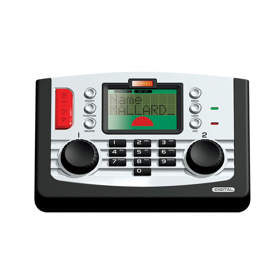
- Page 1 Elite HBook Cover Section 13/3/07 13:07 Page 1 Hornby Hobbies Limited, Margate, Kent CT9 4JX. Tel: +44 (0) 1843 233525 www.hornby.com ‘Elite’ Unit – Operator’s Manual For more information visit: M00000...
- Page 2 255 points or solenoid operated accessories. The following instructions are a guide on how to get the best from your Hornby Elite Digital Control. Please take a little time to carefully read through the instructions before you start to use the Hornby Elite. Should you have any questions then you can either contact Hornby via the Hornby DCC website (www.hornby.com), or write to Hornby using the email...
-
Page 3: Table Of Contents
Elite HBook updated 6.3.07_Q6.qxd 13/3/07 13:09 Page 1 Hornby Digital Elite Setting Up Menu System Guide Making Points Live Quick Start Second Loco Programming Selecting Locomotives to Control Controlling Two Locomotives at the Same Time Acceleration Control Deceleration Control Double Heading... -
Page 4: Setting Up
Please ensure the track and connecting fishplates are clean and are firmly connected. The Hornby Elite unit operates most efficiently when the whole of the layout is “live”. Hornby points are self isolating therefore it is necessary to fit each point with 2 x R8232 Hornby DCC Electric Point Clips. - Page 5 13/3/07 13:09 Page 4 The Hornby Elite Menu System Guide Access the menu options by pressing the Menu button on the Elite Unit. ROTATING Control 1 will cycle through the items shown in RED. Select a menu item by PRESSING Control 1.The unit will then display the chosen sub-menu shown in GREY.
-
Page 6: Quick Start
Making Points ‘Live’ Quick Start The Hornby Elite unit operates most efficiently when the whole of the layout is “live”. Hornby points are self All new factory fitted digital locomotives are programmed No.3 as standard (default). isolating therefore it is necessary to fit each point with 2 x R8232 Hornby DCC Electric Point Clips. Some During the start-up sequence of the Elite the LCD will display: of these clips are included in the Hornby DCC sets, further clips are available from Hornby stockists. -
Page 7: Second Loco Programming
The Elite Digital unit can support 4 types of locomotive programming modes: Direct, Register, Paged and The Hornby Elite Digital Control unit can have stored in its memory 254 digitally controlled locomotives and Operation. For definitions please see page 28. As Direct Programming is now considered to be the 255 solenoid operated accessories.At any one time the Elite can in theory have running (providing the power is... - Page 8 For this example 20 has been selected. Press Control 1. Screen shows “00:00 1 0010”. Press Control 2. Screen shows “00:00 2 0020”. Rotate Control 1 to move the locomotive. Fig 1 Fig 1 www.hornby.com For more information visit:...
- Page 9 1 second per acceleration level “Accel 000”. (e.g. An acceleration level of 10 Please Note: equals 10 seconds approximately). 1 second per acceleration level (e.g. An acceleration level of 10 equals 10 seconds approximately). Fig 1 Fig 1 www.hornby.com For more information visit:...
-
Page 10: Double Heading
10. Press Control 1 to confirm. Screen Please Note: For both locomotives shows “Loco 1 Adr: 0010”. to operate in unison it is important that they each have the same acceleration and deceleration levels. www.hornby.com For more information visit:... -
Page 11: Function Control
Screen shows “M”. Press Control 1 to confirm. “Name” is displayed. Press Menu Press 2 twice. Screen shows to return to the main screen. “MA”. Fig 1 Press 5 four times. Screen shows “MAL”. www.hornby.com For more information visit:... -
Page 12: Speed Step Change
Stop button. Pressing this button causes all activity on the layout to cease. All Hornby decoders are factory set at 128 steps. Locomotive 1 will be used in this example.To alter the Speed Steps place the locomotive on the Programming Track and follow the instructions below. -
Page 13: Analogue Locomotive Control
(0) can be run on a digital layout at support smooth control. anyone time. Press Control 1. Screen shows “Config”. Fig 1 Please Note: See page 25 (Train 0) for enabling the analogue mode on the Elite. www.hornby.com For more information visit:... - Page 14 13:09 Page 22 Setting Up the Elite Unit & Loco Programming Features Having now experienced the initial control and programming abilities of the Hornby Elite the next section of this ® RailCom Enabled / Disabled instruction book is to explain the many additional features that this unit has to offer.
-
Page 15: Clock Setting
Screen shows “Clock X”. Rotate Control 1 until screen Press Menu to return to main shows “Clock X”. screen. www.hornby.com For more information visit: RailCom ® is a registered trade mark of Lenz Systems. -
Page 16: Alternative Programming Modes
Elite Digital unit. The Favourites setting on the Hornby Elite is an extremely useful function for those who have a large stable of locomotives or who use an array of 4 digit ID numbers. Most modellers have special locomotives that they Register Programming Mode always use (Favourites) and these can be ‘marked’... - Page 17 Please note that “DCC Only” For this example rotate Control 1 means that the Elite will support so that screen shows “Power only digital equipped locomotives. DCC Only”. Press Control 1 to (This is a default setting). confirm. www.hornby.com For more information visit:...
-
Page 18: Start Up Voltage Programming (Cv)
Not all electric motors have the same start up voltage requirements.This means that some Digital locomotives equipped then press Control 1 to may require their decoders to be adjusted to compensate for the type of motor used. The Hornby Elite has confirm. If not rotate Control 1 until Rotate Control 1 until screen “RailCom Disable”... -
Page 19: Adjusting The Speed Curve
Rotate Control 1 until screen suitable computer programme to avoid shows “CV 0067 W”. Press uncharacteristic acceleration / Control 1 to confirm. deceleration levels. www.hornby.com For more information visit:... - Page 20 Press Control 1. Screen shows the specification sheet supplied with Please Note: Control 1 until “CV” is shown and “CV 0001 R”. the decoder. The red LED will not flash. press Control 1 to confirm. www.hornby.com For more information visit:...
- Page 21 Accessory Programming (Acc) (continued) To programme a Hornby R8216 Accessory/Point Decoder the Register Mode must be selected. For third Reading CVs on the Main Line party Accessory/Point Decoders an alternative programming mode may be required. In this instance please refer to the programming information supplied with the third party Accessory/Point Decoder.
-
Page 22: Accessory Decoder Direct Cv Programming
Press and release the selected the last accessory operated. control knob. Accessory / point will change direction together with the arrow symbol on the screen. www.hornby.com For more information visit: RailCom ® is a registered trade mark of Lenz Systems. -
Page 23: Overload Safety Cut Off
Press Control 1 to confirm. All Rotate Control 1. Screen shows Eight Hornby Walkabout Select units may be connected to the Elite using the ExpressNet sockets instructions will then be shown in “Unit”. which will allow for individual control of up to 10 locomotives.These units are connected together the chosen language. -
Page 24: Programming Definitions
A technical term referring to the operating information of the particular locomotive or accessory that is stored ® It should be noted that the Hornby R8215 Decoder does not support RailCom therefore if on the specific decoder.This information will remain “set” until changed using the Command Station. - Page 25 Determines whether a locomotive is controlled with 14, 27, 28 or 128 speed steps. direction and any operating functions that the locomotive may have eg lights. Locomotive Decoders can be fitted to accessories that have a motor as a drive for example the R8131 Hornby XpressNet Operating Conveyor or the R8132 Hornby Tipper set.
-
Page 26: Trouble Shooting
Before use the transformer should be examined for damage to the casing, plug pins and cables. In the event of such damage, the Elite unit should not be used until the transformer is replaced with a new Hornby recommended unit. - Page 27 Elite HBook updated 6.3.07_Q6.qxd 13/3/07 13:09 Page 48 Notes Locomotive Address www.hornby.com For more information visit:...
Need help?
Do you have a question about the 'Elite" Unit and is the answer not in the manual?
Questions and answers