
Related Manuals for Aquacom MK-IV

Summary of Contents for Aquacom MK-IV
- Page 1 Aquacom ® MK-IV 3-Diver Intercom Full-Duplex Surface Station for Underwater Communications “Technology in Depth”...
- Page 2 International, Inc., dba Ocean Technology Systems hereinafter referred to as OTS, reserves the right to change specifications without notice. It is recommended that all users read and fully understand this manual before using the MK-IV 3-Diver Intercom. All statements, technical information, and recommendations herein are based on tests we believe to be reliable, but the accuracy or completeness thereof is not guar- anteed;...
- Page 3 Section 1: Introduction ................1 General ..................1 Specifications ................2 Section 2: Equipment Description ............. 3 Package Design ................3 Included with the MK-IV ............. 3 Additional Components, Sold Separately ........3 2.3.1 Communication Cables ..........3 2.3.1.1 ComRopes ........... 3 2.3.1.2...
-
Page 4: Table Of Contents
Table 4: Troubleshooting ..............25–26 Illustrations Figure 1. Examples of Standard and Preamplified Microphones ...4 Figure 2. MK-IV Panel Layout ............... 9 Figure 3. Battery Panel Assembly ............13 Figure 4. Electrical Safety Mechanisms ..........14 Figure 5. Location of Microphone Type Selection Switch ....17... -
Page 5: Section 1: Introduction
MK-IV. If you have any questions, contact your local OTS dealer, or feel free to contact OTS directly... -
Page 6: Specifications
SPECIFICATIONS Input voltage: 90–264 V AC, 47–63 Hz Input current: 5 amps DC Idle current: 125 mA Audio power: 16 watts max (4 watts per diver, 2 watts each for tender headset and speaker) Frequency response: 300–4000 Hz Microphone input impedance: (Non-powered) 150 ohms Headphone impedance output: 300 ohms... -
Page 7: Package Design
5-pin military-style plug on one end that matches the diver umbilical receptacles (Section 2.4, Item 5) on the MK-IV (refer to Table 3, Item 1 in Section 4.2). The other end of the cable should have the connector for your particular earphone- microphone assembly. -
Page 8: Figure 1. Examples Of Standard And Preamplified Microphones
2.3.1.2 Spiral Four: This cable has been used extensively with military and commercial divers for many years. It has been available as military surplus but is becoming harder to find. However, there are some cable manufacturers that have duplicated this cable, and it is now available to the diving community. The most important feature of this cable is the internal wires used for microphone and earphone circuits. -
Page 9: Shielded Cable
2.3.1.3 Shielded Cable: Another available cable contains at least one twisted, shielded balanced cable and a second twisted, shielded or unshielded pair. The unshielded pair is used for the earphones, while the balanced, twisted pair is used for the microphone. Unlike spiral four cable, little can go wrong with this system, provided the microphone is connected to the shielded, twisted, balanced cable. -
Page 10: Earphone-Microphone (Em) Assemblies
(non-powered) EM assemblies available for use with a ComRope connected to the MK-IV 3-Diver Intercom. Note: If you have a diving helmet or mask that is not on the compatibility chart, contact OTS or your local OTS dealer for availability or for information on custom EM assemblies. -
Page 11: Table 1: Compatible Em Assemblies With Standard Microphones
Table 1: Compatible EM Assemblies with Standard Microphones Earphones Part Num- Micro- Sin- Model Number phone Dual Mask Type EMA-2 911060-001 Hot-Mic All Divator MK II FFMs ® Super EMA-2SM 911060-098 All Divator MK II FFMs ® EMX-2 911060-008 Hot-Mic EXO-26 original FFM ®... -
Page 12: Emdg-2 (911060-076)
2.3.3.10 EMD-2 (911060-067): The EMD-2 EM assembly is designed to be installed into the M-48 SuperMask FFM. It consists of two earphones, earphone ® holders, a Hot-Mic, a Hi-Use connector, and a PTT button. ® 2.3.3.11 EMD-2SM (911060-101): The EMD-2SM EM assembly is designed to be installed into the M-48 SuperMask FFM. -
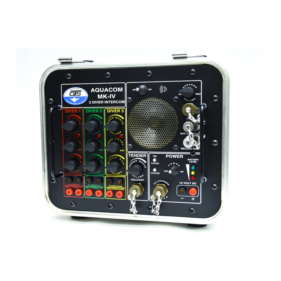
Page 13: Figure 2. Mk-Iv Panel Layout
FUNCTIONS Figure 2 depicts the MK-IV panel with its controls and connections. The numbered text below is the key to the indexed items in Figure 2. Boldfaced text in all capital letters refers to the label on the panel. DIVER MOUTH VOlUME (1 of 3): Volume control knob for listening to diver speech. - Page 14 13. bATTERY lEVEl: Three LEDs that illuminate to indicate the battery volt- age level, as explained in Section 3.1. 14. Handle (1 of 2): Handles for lifting either the MK-IV unit (with the case open) or the panel out of the case.
-
Page 15: Battery Charging
3.1.1 bATTERY CHARGING: The MK-IV is equipped with an internal bat- tery charger, so one only has to connect the MK-IV to an AC power source (per the instructions in Section 3.2) to recharge the battery. Safety Precautions: While charging the battery it is very important to open the MK-IV’s lower... -
Page 16: Battery Replacement
(by rotation fully clockwise, to prevent water entry). Because the ventilation port should be open while AC power is used and the battery recharges, the MK-IV should be operated in such a way as to minimize contact with splashing or spraying water. Operation away from direct contact with salt water or freshwater splashes or sprays is always recommended when operating 110/220-volt mains-powered electronics. -
Page 17: Ac Power
10. Connect the battery leads (red = positive, black = negative) as marked on the battery. IMPORTANT NOTE: Always connect the positive (red) lead first. 11. Reinstall the MK-IV panel, being careful not to contact the thermal breaker (Fig. 3, #7) and GFCI (#6) switches against the flange of the case (doing so might trip the switches). -
Page 18: Figure 4. Electrical Safety Mechanisms
GFCI should be accessed only by a qualified technician; furthermore, the MK-IV must be in a dry environment and on a stable surface. Refer to Figure 3, Item 6, for the location of the GFCI. A green LED (Fig. 4, #2) dimly illuminates to indicate the GFCI is active. -
Page 19: External Dc Power
AC power to the unit. If the thermal breaker trips, it must be reset before the MK-IV can be used again with AC power. To do so, the panel assembly must be removed (follow steps 1–4 of Section 3.1.2). -
Page 20: Section 4: Operation
ADjUSTMENTS AND CONTROlS The MK-IV 3-Diver Intercom has various controls that allow you to customize and adjust the settings to your preference, to provide optimal communications for your situation. This section describes the available controls. -
Page 21: Figure 5. Location Of Microphone Type Selection Switch
The MK-IV has a toggle switch to select the type of microphone used by the divers (Fig. 5). When the switch is set for use of a power mic, the red “mic power” indicator LED (Fig. -
Page 22: Diver Ptt Control
Using a #2 Phillips screwdriver, remove and set aside the fourteen panel screws (Fig. 2, #21) and neoprene seals. 4. Using the two handles (Fig. 2, #14), remove the front panel. The MK-IV’s internal hardware and electronics are attached to the panel, so it is fairly heavy and requires special care when being handled. -
Page 23: Speaker Power And Volume
3. Diver microphone type selection: Follow the instructions in Section 4.1.2.3 to select the type of microphone the divers will be using. 4. Test of GFCI electrical safety mechanism: If you are going to use the MK-IV with AC power, we recommend you test the GFCI according to the instructions in Section 3.2.1.1 (GFCI). -
Page 24: Table 3: Connectors And Wiring Of External Devices
Table 3: Connectors and Wiring of External Devices Connector Connector Item Connection OTS P/N Industry P/N Signal Diver umbilicals 211218-000 MS3116E14-5P Mic ground Mic signal Ear signal Ear signal Chassis ground Tender headset J070-5 MS3116E10-98P Tender mic signal Tender mic return Tender ear signal Tender ear return Chassis ground... -
Page 25: Reception
(Fig. 2, #15, #16 and #17). Power connection: If an AC power source will be used to operate the MK-IV, follow the instructions in Section 3.2. If a DC source is to be used, follow the instructions in Section 3.3. -
Page 26: Recording Communications
Section 5.1 to maintain your MK-IV in optimal condition. If the MK-IV is going to be transported airborne, open both safety vents to depres- surize the unit’s interior during flight. The valves are located on the upper and lower halves of the case’s front with the panel facing upward and are opened by fully... - Page 27 diver should then respond to inform you that he is listening (e.g., “Topside, this is Alpha Diver, go ahead”). Avoid excessive tender-to-diver volume. Most of the time, when there is too much volume, the diver will hear distortion and ask for more volume! Speak slowly in one brief, continuous sentence.
-
Page 28: Section 5: Maintenance And Troubleshooting
MK-IV: 1. Clean the MK-IV by wiping it free of dirt, debris, and water with a clean, soft cloth. Warm water with a small amount of nonabrasive soap is the recommended cleaning solution. -
Page 29: Table 4: Troubleshooting
Table 4: Troubleshooting Problem Probable Cause Remedy No power Battery exhausted Recharge battery. Battery leads loose Check battery connections. Defective ON/OFF Change switch. switch Board connector Clean pins. not making contact Open circuit on board Repair or replace board. GFCI switch defective Check GFCI switch. - Page 30 Table 4 (continued) Problem Probable Cause Remedy Damaged power cord Check power cord. GFCI switch defective Check GFCI switch. or tripped Thermal breaker switch Check thermal breaker defective or tripped switch. No diver voice Microphone type Check for correct dyn/power incompatibility mic selection for type of microphones.
- Page 31 APPENDIX SPARE COMPONENTS AND PARTS Part Description OTS P/N U.S. Military P/N Figure:Item 1) THB-16 tender headset 900298-032 with boom microphone 2) AC power/charging cable 914081-000 3) RB-1 battery 910319-000 4) Panel screw 244004-000 2:21 5) Panel sealing washer 245051-001 6) Panel handles 243007-000 2:14...
-
Page 32: Limited Warranty
Ocean Technology Systems lIMITED WARRANTY Ocean Technology Systems’ Aquacom MK-IV 3-Diver Intercom is fully ® warranted against defects in materials and workmanship for a period of one year from the time of purchase. Our obligation under this warranty is limited to the replacement of any part or parts that prove to our satisfaction to have been defective and that have not been misused or carelessly handled.
Need help?
Do you have a question about the MK-IV and is the answer not in the manual?
Questions and answers