
Related Manuals for Makita BMR102


Summary of Contents for Makita BMR102
-
Page 1: Instruction Manual
INSTRUCTION MANUAL Radio BMR102 WARNING: For your personal safety, READ and UNDERSTAND before using. SAVE THESE INSTRUCTIONS FOR FUTURE REFERENCE. -
Page 2: Specific Safety Rules
• Water resistant to IPX 4 screws, or other small metal objects that can make a • Powered by both Makita battery pack and supplied connection from one terminal to another. Shorting the power adaptor battery terminals together may cause sparks, burns, or a fire. -
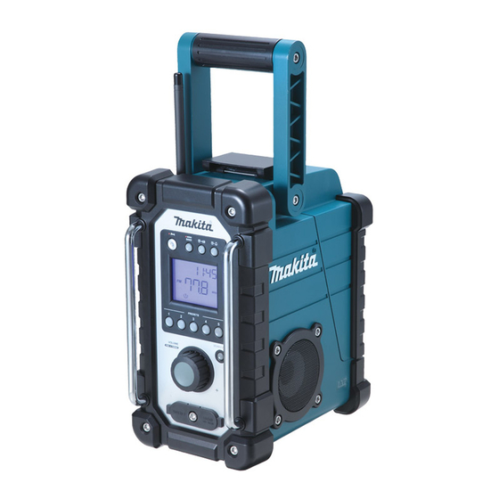
Page 3: Explanation Of General View
Explanation of general view Controls: 9. Input terminal (AUX IN1) 10. Soft bended rod antenna 1. Power and Sleep timer 11. Battery compartment (covering main battery pack and 2. Band and Mono button back up batteries) 3. Radio alarm set 12. -
Page 4: Battery Installation And Voltage
LCD Display: 1. Battery compartment A. Radio alarm (covering main B. HWS buzzer alarm battery pack and C. Scan tuning back up D. Band Indicator batteries) E. Low battery indicator 2. Battery F. Preset stations compartment G. Sleep and Snooze status locker H. - Page 5 1. Battery cartridge WARNING: Do not use two main batteries at the same time. 3-1. Installing or removing Slide battery cartridge 1. Red indicator 2. Button 3. Battery cartridge 1. Battery cartridge • To install the battery cartridge, align the tongue on the battery cartridge with the groove in the housing and slip it into place.
-
Page 6: Settings And Functions
Installing the Soft bended rod 4. Rotate Tuning/Volume control knob to set the required hour. antenna 5. Press button to confirm hour setting, the minute digit will flash. 1. Soft bended rod 6. Rotate Tuning/Volume control knob to set the required antenna minute. -
Page 7: Storing Stations In Preset Memories
5. Rotate the Tuning/Volume control knob to get required button to complete radio alarm setting. sound level. Display will show 6. To turn off the radio, press the Power button. Display 2. When above radio alarm time and station are set, will show OFF. -
Page 8: Specifications
CD player) to either AUX 1 or AUX 2 by audio cord. Weight (without battery) • Repeatedly press and release the Band button until 4.0 kg “AU1” or “AU2” is displayed, then AUX function is activated. • AUX can’t be activated as alarm source. Makita Corporation Anjo, Aichi, Japan www.makita.com BMR102_ENEU_1011...