
Related Manuals for Lasermark LMH

Summary of Contents for Lasermark LMH
- Page 1 INSTRUCTION MANUAL LMH Series Electronic Self-Leveling Rotary Laser LMH | LMH-C | LMH-GR | LMH600 57-LMH Shown LMH Series Rotary Lasers • 1...
- Page 2 The information contained herein is proprietary information of CST/berger, and is subject to change without notice. CST/berger is a division of Stanley Works® This document shall not be copied or otherwise reproduced without CST/berger's written consent. 2 • LMH Series Rotary Lasers...
-
Page 3: Table Of Contents
Upright Position Peg Test (X axis) ..............18 6.1.2 Upright Position Calibration - X axis (LMH, LMH-C, LMH-GR) ......19 6.1.3 Upright Position Peg Test and Calibration - Y axis (LMH, LMH-C, LMH-GR) ...20 6.2.1 Upright Position Calibration (LMH600) ............21 6.2.2 Laydown Position Calibration (LMH600) ............22 Care of LMH Instrument ............ -
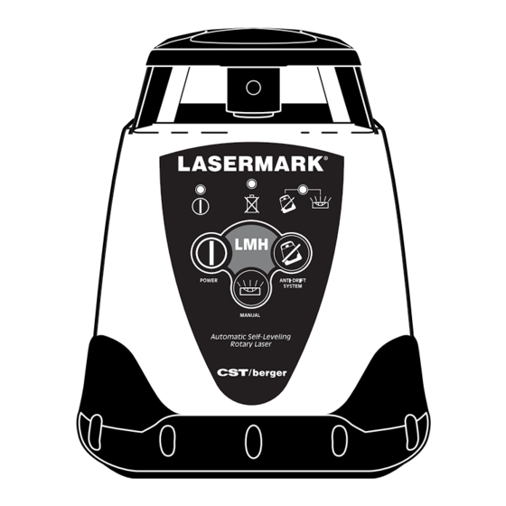
Page 4: Lmh Features
Button MANUAL Manual Automatic Self-Leveling Rotary Laser Mode POWER ANTI-DRIFT SYSTEM Battery Compartment Access/ ⁄ " x 11 Tripod Mounting Thread MANUAL Automatic Self-Leveling Rotary Laser SIDE VIEW LOCATION OF CALIBRATION BUTTONS Built-In Handle 4 • LMH Series Rotary Lasers... - Page 5 LEVEL ON/OFF (See LMH600) Adjustment Manual Buttons Grade Setting Battery Compartment Access/ ⁄ " x 11 Tripod Mounting Thread ANTI-DRIFT SYSTEM POWER SIDE VIEW LEVEL ON/OFF Manual Grade Setting Built-In Handle LOCATION OF CALIBRATION BUTTONS LMH Series Rotary Lasers • 5...
- Page 6 ⁄ " x 11 Tripod Mounting Thread Down Position LMH600 Self-Leveling Rotary Laser (Vertical Mode), for Vertical Laydown Set-ups Button also used in normal operation to activate ADS LOCATION OF CALIBRATION BUTTONS LMH600 Shown 6 • LMH Series Rotary Lasers...
-
Page 7: Laser Safety
DO NOT stare directly at the laser beam or project the laser beam directly into the eyes of others. Serious eye injury could result. DO NOT place the LMH in a position that may cause anyone to stare into the laser beam intentionally or unintentionally. Serious eye injury could result. -
Page 8: Electrical Safty Procedures
ALWAYS turn the LMH "OFF" when not in use. Leaving the LMH "ON" increases the risk of someone inadvertently staring into the laser beam. DO NOT operate the LMH in combustible areas such as in the presence of fl ammable liquids, gases or dust. -
Page 9: Certifi Cations
1040.10 and 10040.11 except for deviations pursuant to Laser notice No. 50, dated July 26, 2001. This LMH has also been tested and complies with the CE certifi cation requirements set forth in the EC regulations 89/336/EEC and EN 61000-6-1 (EN50082-1), EN 61000-6-3 (EN50081-1) and EN 60825-1. -
Page 10: Re-Leveling
To make the unit return to ADS as default, repeat these instructions. When the LMH Series laser is fi rst turned ON, the ADS feature does not begin recording for 1 minute. This allows the instrument to be set up and adjusted. -
Page 11: Grade Mode: Single Axis Grade (Lmh-Gr And Lmh600 Only)
3.4 Grade Mode: Single Axis Grade (LMH-GR and LMH600 Only) The single grade function is ideal for general site grading, checking excavations, landscaping and drainage, and more. Manual grade mode can be activated by placing the automatic leveling sensor in the OFF position. - Page 12 Fig. 5B 3.4.1 Manual Mode (LMH and LMH-C). Manual mode disengages the leveling feature; allowing the instrument to be placed in any position (to grade). To activate the Manual Mode, Turn off the ADS (if it is on) and then press the MANUAL mode button.
-
Page 13: Grade Mode: Dual Axis Slope (Lmh600 Only)
(Fig. 5B). Allow the unit ample time to react to the button being pressed. Refer to examples in Fig. 6 to predict your results. X= –10.00% Y= –10.00% X= +10.00% Y= +10.00% X= –10.00% Y= +10.00% Fig. 6 LMH Series Rotary Lasers • 13... -
Page 14: Lmh Applications
4.1 Procedures for Ceiling Grid Applications (LMH600 Only) 1: Attach the LMH 600 to the optional wallmount bracket. Be sure the control buttons are facing outward. Tighten- ing the locking screw will secure the unit to the bracket. -
Page 15: Procedures For Laydown Applications
4.2 Procedures for Laydown Applications (LMH600 Only) 1: Place the unit in the laydown position on a fl at, level surface. 2: Press the Power button. If the "Out-of-Level" indicator is blinking, LMH600 Shown LMH Series Rotary Lasers • 15... -
Page 16: Procedures For General Construction Applications
4.3 Procedures for General Construction Applications Note: A level plane of laser light is created by the rotating beam of the LMH Series. The laser light can be used to reference elevations with the use of a laser detector. 1: Place the unit on a fl at, level surface such as a tripod. Setup the unit in an area where it can not be obstructed and it will be set at a convenient height. -
Page 17: Lmh Battery Replacement
Then plug the charger into the appropriate 120/230V AC outlet. Charge time is typically around 8 hours. The LMH can be charged and used at the same time, but only a minimal charge will be applied to the battery pack. -
Page 18: Lmh Calibration
(Fig. 9). You will need to refer to this to complete the following steps. Fig. 9 6.1 Upright Position Peg Test (X axis) 1: To test the X axis, mount the LaserMark ® on a tripod or a level, sturdy surface and place approximately 100 feet (30m) away from a wall. -
Page 19: Upright Position Calibration - X Axis (Lmh, Lmh-C, Lmh-Gr)
6.1.2 Upright Position Calibration - X axis (LMH, LMH-C, LMH-GR) 1: Keep the unit in its current position. Calibration Mode Power Off the unit. X Axis active 2: Power On the unit while holding the ADS button down. You will know if Calibration mode is activated when the Battery Low and ADS LEDs fl... -
Page 20: Upright Position Peg Test And Calibration - Y Axis (Lmh, Lmh-C, Lmh-Gr)
6.1.3 Upright Position Peg Test and Calibration - Y axis (LMH, LMH-C, LMH-GR) If you wish to test the Y axis at the same time as the X axis, simply keep the unit on from when you tested the X axis and rotate the unit 90°... -
Page 21: Upright Position Calibration (Lmh600)
fi gure 17. 4: follow 6.1.2, steps 4 through 5. Rotate unit 90 degree to calibrate the other axis. 5: Press the POWER button. This will exit Calibration Mode. Fig. 17 LMH Series Rotary Lasers • 21... -
Page 22: Laydown Position Calibration (Lmh600)
DOWN ARROW buttons to adjust the beam, until it intersects the plumb line. 6: Press the POWER button. This will exit Calibration Mode. Rotating Beam (Dashed Line) is shown NOT in-line with plumb line Plumb Beam Fig. 18 22 • LMH Series Rotary Lasers... -
Page 23: Care Of Lmh Instrument
" 4 ⁄ 3 " 8 Dimensions Weight ± Power 60±hrs intermittent use LMH, LMH-C; 55hrs intermittent use LMH-GR, LMH600 (variable with temperature) Battery Life 30± hrs intermittent use with fully charged battery pack 600 RPM 600 RPM 600 RPM Rotation Speed 22ºF to 120ºF... -
Page 24: Troubleshooting
9. TROUBLESHOOTING The following information lists basic tests that can be performed to check the LMH in the event of poor performance. Check Your Batteries: One of the most common causes of perfor- mance failures is due to defective or incorrectly installed batteries. - Page 25 LMH Series Errors: When an error occurs on the LMH Series, turn the unit OFF. Wait 15 seconds, then turn unit ON. If these procedures do not correct error, contact CST/berger. X—AXIS ERROR Y—AXIS ERROR SPINDLE ERROR LMH600 X—AXIS ERROR Y—AXIS ERROR...
-
Page 26: Warranty
10. WARRANTY This LaserMark ® LMH Automatic Self-Leveling Rotary Laser is warranted to the original purchaser to be free from defects in workmanship and material. CST/berger will repair or replace any defective part which may malfunction under normal and proper use within a period of... -
Page 27: Universal Laser Detector
Battery Door 3. POWER A 9-volt battery will provide up to 3 months of typical usage. When the unit is turned on and the low battery symbol remains lit, the battery should be replaced. LMH Series Rotary Lasers • 27... - Page 28 If the detector is not struck by a laser beam after 5-8 minutes, the detector will automatically shut itself off to preserve battery life. Turn the unit back on using the power button. 28 • LMH Series Rotary Lasers...
- Page 29 (sensitivity based on standard conditions with most lasers; may vary slightly due to make, manufacturer, beam size, or working conditions) Readout: LCD, LD400-front and rear windows; LD100N-single window Power: One 9-volt battery; provides 3 months of typical usage LMH Series Rotary Lasers • 29...
-
Page 30: Remote Control
(1) Variable Rotation – places instrument in Rotation Mode and adjusts to preset rotational speeds. (2) Left Arrow and (3) Right Arrow– Line positioning in laydown position and Grade Adjustment X-Axis – Only in manual mode. of the laser. 30 • LMH Series Rotary Lasers... - Page 31 Counter-clock-wise Head Positioning Line Positioning (Vertical)– Left, Right Remote is designed for use with rotary laser models– all control buttons may not be used for some lasers. Refer to chart above (n/a– no function). RC700 LMH Series Rotary Lasers • 31...
- Page 32 05/07 Z94-LMHSERIES 32 • LMH Series Rotary Lasers...
Need help?
Do you have a question about the LMH and is the answer not in the manual?
Questions and answers