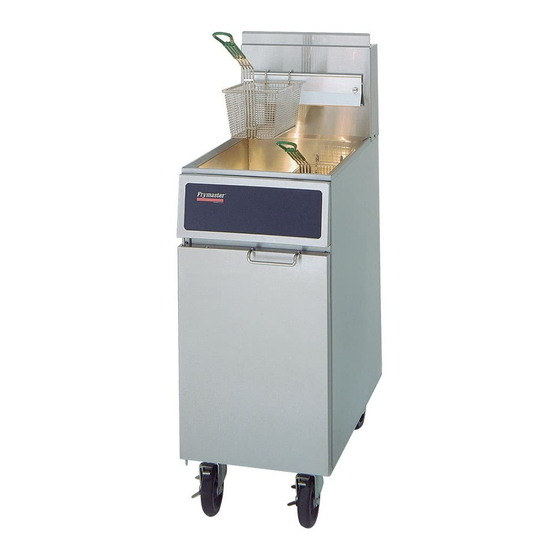
Frymaster GF14 Series Service & Parts Manual
Gas fryers
Hide thumbs
Also See for GF14 Series:
- Service manual (32 pages) ,
- Installation & operation manual (26 pages) ,
- Manual (2 pages)

Related Manuals for Frymaster GF14 Series


Summary of Contents for Frymaster GF14 Series
- Page 1 Frymaster, a member of the Commercial Food Equipment Service Association, recommends using CFESA Certified Technicians. 24-Hour Service Hotline 1-800-551-8633 APRIL 2009 *8195888*...
- Page 2 DANGER No structural material on the fryer should be altered or removed to accommodate placement of the fryer under a hood. Questions? Call the Frymaster/Dean Service Hotline at 1-800-551-8633.
- Page 3 DANGER Adequate means must be provided to limit the movement of this appliance without depending upon the gas line connection. Single fryers equipped with legs must be stabilized by installing anchor straps. All fryers equipped with casters must be stabilized by installing restraining chains.
-
Page 4: Table Of Contents
GF14 and GF40 SERIES GAS FRYERS TABLE OF CONTENTS CHAPTER 1: Service Procedures Functional Description..................1-1 Accessing Fryers for Servicing................1-2 Cleaning the Gas Valve Vent Tube ..............1-2 Checking the Burner Manifold Pressure.............. 1-3 Adjusting Deflector Spacing and Alignment............1-3 Adjusting the Pilot Flame .................. -
Page 5: Chapter 1: Service Procedures
GF14/GF40 SERIES GAS FRYERS CHAPTER 1: SERVICE PROCEDURES NOTE: This manual is to be used in conjunction with the GF14/GF40 Installation and Operation Manual (P/N 819-8887). Be sure to have both manuals on hand when making service calls. Functional Description The GF14 and GF40 Series fryers contain a welded steel (stainless or cold-rolled) frypot that is directly heated by gas flames that are diffused evenly over its lower surface by deflectors. -
Page 6: Accessing Fryers For Servicing
Pilot Ignition System The pilot ignition system is made up of the pilot orifice, pilot hood, and a thermopile. The pilot serves two purposes: lighting the burner and heating the thermopile. In operation, the thermopile is in contact with the pilot flame and generates millivolts. The millivolt output passes through a normally closed high-limit switch and energizes the gas valve pilot coil, which in turn opens the pilot valve. -
Page 7: Checking The Burner Manifold Pressure
Refer to Quarterly Checks and Services in Chapter 4 of the Installation and Operation manual. Checking the Burner Manifold Pressure Refer to Semi-Annual Checks and Services in Chapter 4 of the Installation and Operation manual. Adjusting Deflector Spacing and Alignment DANGER Drain the frypot or remove the handle from the drain valve before proceeding further. -
Page 8: Replacing Fryer Components
Remove this cap to access the pilot flame adjustment screw. 2. Using a small, flat-tipped screwdriver, turn the pilot flame adjustment screw counterclockwise to increase the length of the flame or clockwise to decrease the length of the flame. Adjust the flame to a length of 1 to 1½... -
Page 9: Replacing The High-Limit Thermostat
Compression Nut Thermostat Bulb Capillary Tube Large fitting screws Attach wire 2C to into frypot. this terminal. Attach wire 1C to Carefully coil excess this terminal. capillary tube after securing thermostat bulb to frypot and tightening compression nut. Thermostat Control 7. -
Page 10: Replacing Deflectors
Attach hi-limit wires to these terminals. Polarity does not matter. 1.7.3 Replacing Deflectors Drain the fryer and disconnect it from the gas supply. Disconnect the wires from the gas valve terminal block, marking each wire to facilitate reconnection. Disconnect the pipe union collar at the right side of the gas valve. On GF40 fryers, remove the burner heat shield hanger screws at the front of the burner and remove the heat shield. -
Page 11: Replacing The Gas Valve
To replace the entire target assembly, use a ½-inch box end wrench to remove the brass orifices that hold the assembly to the burner manifold. Position the new assembly and reinstall the orifices. WARNING Use extreme care to prevent cross-threading and stripping when reinstalling the brass orifices. - Page 12 Mounting screws pass through this bracket from the rear. Mounting Screws On GF14 units, the pilot and thermopile assembly can On GF40 units, the pilot and thermopile assembly is attached to its mounting bracket by two screws that pass be removed by disconnecting the pilot tube and through the bracket from the rear.
-
Page 13: Replacing The Frypot
1.7.6 Replacing the Frypot 1. Drain the frypot and disconnect the fryer from the gas supply. 2. Remove all accessories (e.g., frypot covers, drop-in probes, basket hangers, etc.). 3. Remove the screws from the sides and back of the flue cap and lift it off the fryer. 4. -
Page 14: Leaking
4. Leaking The probable causes and corrective actions for each category are discussed in the following sections. 1.8.1 Pilot Failures Pilot failures fall into one or the other of two categories – failure to light or failure to remain lit. Pilot Fails to Light 1. - Page 15 Section 1.7. If the flame is being blown away from the pilot, eliminate the draft that is causing it to be blown away from the thermopile. If the pilot flame correctly impinges the tip of the thermopile, connect a multimeter in series with either of the thermopile leads and its gas valve terminal.
- Page 16 1.8.3 Improper Temperature Control (i.e., failure to control at set point) Temperature control is a function of several interrelated components, each of which must operate correctly. The principle component, however, is the thermostat. The thermostat should be checked periodically. Causes for temperature control problems are damage to the thermostat bulb, kinking of the capillary tube, and broken or loose wiring.
-
Page 17: Wiring Diagrams
1.9 Wiring Diagram 1.9.1 Current Production Units with Honeywell Gas Valve High-Limit Thermostat Thermopile Operating Thermostat 1-13... -
Page 18: Early Production Units With Robertshaw Gas Valve
1.9.2 Early Production Units with Robertshaw Gas Valve Operating Thermostat Thermopile 1-14... -
Page 19: Chapter 2: Gf14 Parts Lists
GF14/GF40 SERIES GAS FRYERS CHAPTER 2: GF14 PARTS LIST ACCESSORIES Item Part # Component 803-0015 Basket, Full 803-0032 Rack, Basket Support 803-0197 Cleanout Rod, 27-Inch 803-0271 Basket, Twin 806-5518 Cover, Frypot 910-7014 Cover, Spreader Cabinet Quick-Disconnect Fitting, Female 810-0070 ¾-inch 810-0073 1-inch Quick-Disconnect Fitting, Male... -
Page 20: Burner And Gas Supply Components
BURNER AND GAS SUPPLY COMPONENTS... - Page 21 Item Part # Component 200-0176 Bracket, Front Manifold Mounting 200-0177 Hanger, Rear Manifold 200-0749 Guard, Thermopile Valve, Honeywell Millivolt Gas (See NOTE 1.) 807-1603 Natural (See NOTE 2.) 807-1604 Propane (See NOTE 2.) 809-0092 Screw, 5-40 x ¼-inch Slotted Pan Head 809-0105 Screw, #8 x ⅜-inch Slotted Hex Washer Head 809-0173...
-
Page 22: Cabinetry Components
CABINETRY COMPONENTS... - Page 23 Item Part # Component 210-0384 Cap, Flue 806-3811 Leg (set of 4) 806-8396 Door Assembly 826-1351 Retainer, Nut (Nutsert) (package of 10) 826-1362 Nut, ¼-20 Hex (package of 10) 809-0171 Thumbscrew, ¼-20 x 1⅜-inch 809-0191 Washer, ¼-inch Lock 809-0193 Washer, ¼-inch Nylon Flat 826-1371 Screw, #8 X ½-inch Hex Head Drill Point (package of 25) 826-1374...
-
Page 24: Frypot And Related Components
FRYPOT AND RELATED COMPONENTS... - Page 25 Item Part # Component Complete Replacement Frypot with Flue and Insulation Installed 806-3958SP Stainless Steel 806-3959SP Cold-Rolled Steel 806-9710SP Stainless Steel (for SYSCO fryers w/Fenwal thermostat only) 806-4006 Complete Front Combustion Chamber (Items 6, 8, 12, and 19) 826-1177 Thermostat Assembly, High Limit 807-1692 Thermostat, Sunne Operating 816-0578...
-
Page 26: Chapter 3: Gf40 Parts Lists
GF14/GF40 SERIES GAS FRYERS CHAPTER 3: GF40 PARTS LIST ACCESSORIES Item Part # Component 803-0099 Basket, Full 803-0132 Rack, Basket Support 803-0197 Cleanout Rod, 27-Inch 803-0271 Basket, Twin 806-5518 Cover, Frypot 910-7014 Cover, Spreader Cabinet Quick-Disconnect Fitting, Female 810-0070 ¾-inch 810-0073 1-inch Quick-Disconnect Fitting, Male... -
Page 27: Burner And Gas Supply Components
BURNER AND GAS SUPPLY COMPONENTS... - Page 28 Item Part # Component 200-0749 Guard, Thermopile 806-0225SP Deflector Assembly Valve, Honeywell Millivolt Gas (See NOTE 1.) 807-1603 Natural (See NOTE 2.) 807-1604 Propane (See NOTE 2.) 809-0092 Screw, 5-40 x ¼-inch Slotted Pan Head 809-0115 Screw. #10-32 x ¼-inch Truss Head (attaches Item 10 to Item 22) 809-0785 Screw, #14 x ¾-inch Slotted Hex Washer Head 809-0951...
-
Page 29: Cabinetry Components
CABINETRY COMPONENTS... - Page 30 Item Part # Component 806-8396 Door Assembly 826-1351 Retainer, Nut (Nutsert) (package of 10) 826-1362 Nut, ¼-20 Hex (package of 10) 809-0171 Thumbscrew, ¼-20 x 1⅜-inch 809-0191 Washer, ¼-inch Lock 809-0193 Washer, ¼-inch Nylon Flat 826-1371 Screw, #8 X ½-inch Hex Head Drill Point (package of 25) 826-1374 Screw, #10 X ½-inch Hex Head (package of 25) 809-0413...
-
Page 31: Frypot And Related Components
FRYPOT AND RELATED COMPONENTS... - Page 32 Item Part # Component Complete Replacement Frypot with Flue and Insulation Installed 106-1679SP Stainless Steel 806-4199SP Cold-Rolled Steel 806-4308SP Complete Front Combustion Chamber (Items 1 and 19 through 23) 900-6969 Baffle, Front Insulation 806-5566 Panel Assembly, Rear Combustion Chamber 806-5567SP Flue Assembly with Insulation, Complete 816-0174 Insulation, Flue Back...
- Page 33 THIS PAGE INTENTIONALLY LEFT BLANK...
- Page 34 Shipping Address: 8700 Line Avenue, Shreveport, Louisiana 71106 TEL 1-318-865-1711 FAX (Parts) 1-318-219-7140 FAX (Tech Support) 1-318-219-7135 SERVICE HOTLINE 819-5888 PRINTED IN THE UNITED STATES 1-800-551-8633 APRIL 2009...
Need help?
Do you have a question about the GF14 Series and is the answer not in the manual?
Questions and answers