Table of Contents
Advertisement
Advertisement
Table of Contents

Related Manuals for Extech Instruments EX540


Summary of Contents for Extech Instruments EX540
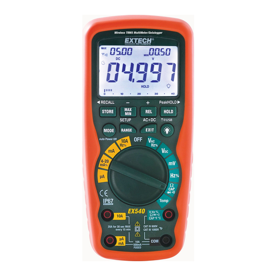
- Page 1 User's Guide Wireless TRMS Multimeter Model EX540...
- Page 2 Note – Examples include switches in the fixed installation and some equipment for industrial use with permanent connection to the fixed installation. OVERVOLTAGE CATEGORY IV Equipment of OVERVOLTAGE CATEGORY IV is for use at the origin of the installation. Note – Examples include electricity meters and primary over-current protection equipment EX540-EN V1.2 7/10...
-
Page 3: Safety Instructions
NEVER operate the meter unless the back cover and the battery and fuse covers are in place and fastened securely. If the equipment is used in a manner not specified by the manufacturer, the protection provided by the equipment may be impaired. EX540-EN V1.2 7/10... -
Page 4: Controls And Jacks
Direct current HOLD Display hold ºF Degrees Fahrenheit ºC Degrees Centigrade Maximum Minimum Serial number second Set up parameter AC+DC Alternating current + Direct current TRMS True RMS Store Recall AUTO Auto Range Auto Power off enabled Backlight EX540-EN V1.2 7/10... -
Page 5: Dc Voltage Measurements
Read the frequency in the main display. Press the MODE button again to indicate “%”. Read the % of duty cycle in the main display. With ACV in the main display, press EXIT for 2 seconds to measure AC+DC. EX540-EN V1.2 7/10... -
Page 6: Mv Voltage Measurements
Touch the black test probe tip to the negative side of the circuit. Touch the red test probe tip to the positive side of the circuit. Apply power to the circuit. Read the current in the display. EX540-EN V1.2 7/10... -
Page 7: Ac Current (Frequency, Duty Cycle) Measurements
Touch the test probe tips across the circuit or part under test. It is best to disconnect one side of the part under test so the rest of the circuit will not interfere with the resistance reading. Read the resistance in the display. EX540-EN V1.2 7/10... -
Page 8: Continuity Check
Insert the black test lead banana plug into the negative COM jack. Insert the red test lead banana plug into the positive V jack. Press the MODE button to indicate “F” Touch the test leads to the capacitor to be tested. Read the capacitance value in the display EX540-EN V1.2 7/10... -
Page 9: Temperature Measurements
“max” occurs.The display icon "MIN" will appear. The right auxiliary displaymeter will display and hold the minimum reading and will update only when a new “min” occurs. To exit MAX/MIN mode press EXIT EX540-EN V1.2 7/10... -
Page 10: Relative Mode
Set the sample rate to 1 to 255 S for automatic recording. In this mode, pressing the STORE button will start data recording at the set sample rate. Press the EXIT button to end the recording session. EX540-EN V1.2 7/10... -
Page 11: Clearing Memory
2 seconds to enter into AC+DC testing. The precision is the same as in the AC measure modes. The LCD shows AC+DC icon. Press the EXIT button to exit the mode. LOW BATTERY INDICATION When the icon appears in the display, the battery should be replaced EX540-EN V1.2 7/10... -
Page 12: Maintenance
6. IF THE METER IS TO BE STORED FOR A LONG PERIOD OF TIME, the batteries should be removed to prevent damage to the unit. EX540-EN V1.2 7/10... -
Page 13: Battery Installation
WARNING: To avoid electric shock, do not operate the meter until the battery cover is in place and fastened securely. NOTE: If your meter does not work properly, check the fuses and batteries to make sure that they are still good and that they are properly inserted. F1 F2 EX540-EN V1.2 7/10... -
Page 14: Replacing The Fuses
—Connect the equipment into an outlet on a circuit different from that to which the receiver is connected. —Consult the dealer or an experienced radio/TV technician for help. Warning: Changes or modifications not expressly approved by the party responsible for compliance could void the user's authority to operate the equipment. EX540-EN V1.2 7/10... -
Page 15: Specifications
(20A: 30 sec max with reduced accuracy) All AC voltage ranges are specified from 5% of range to 100% of range NOTE: Accuracy is stated at 65 F to 83 F (18 C to 28 C) and less than 75% RH. EX540-EN V1.2 7/10... - Page 16 0mA=-25%, 4mA=0%, 20mA=100%, 24mA=125% Note: Accuracy specifications consist of two elements: • (% reading) – This is the accuracy of the measurement circuit. • (+ digits) – This is the accuracy of the analog to digital converter. EX540-EN V1.2 7/10...
- Page 17 EN61010-1 and IEC61010-1 2 Edition (2001) to Category IV 600V and Category III 1000V; Pollution Degree 2. The meter also meets UL 61010-1, Edition (2004), CAN/CSA C22.2 No. 61010-1 2 Edition (2004), and UL 61010B-2-031, 1 Edition (2003) EX540-EN V1.2 7/10...
-
Page 18: Product Support
A Return Authorization (RA) number must be issued before any product is returned to Extech. The sender is responsible for shipping charges, freight, insurance and proper packaging to prevent damage in transit. This warranty does not apply to defects resulting from action of the user such as misuse, improper wiring, operation outside of specification, improper maintenance or repair, or unauthorized modification. -
Page 19: Garantie
Web à l’adresse www.extech.com pour obtenir nos coordonnées numéro d’autorisation de retour (AR) doit être délivré avant tout retour de produit à Extech. L’expéditeur prend à sa charge les frais d’expédition, le fret, l’assurance et l’emballage correct de l’appareil afin de prévenir toute détérioration durant le transport.
Need help?
Do you have a question about the EX540 and is the answer not in the manual?
Questions and answers