Motorola AP650 Installation Manual
Hide thumbs
Also See for AP650:
- Installation manual (38 pages) ,
- Reference manual (954 pages) ,
- Installation manual (40 pages)
Table of Contents
Advertisement
Advertisement
Table of Contents

Related Manuals for Motorola AP650


Summary of Contents for Motorola AP650
- Page 1 AP650 Access Point INSTALLATION GUIDE...
-
Page 2: Table Of Contents
2.7 External Antenna Model Suspended Ceiling Tile (Plenum) Mount Instructions ......... 13 2.7.1 Suspended Ceiling Mount Hardware ..................13 2.7.2 Ceiling Mount Procedure ......................14 2.8 AP650 External Antenna Model Antenna Options ................15 2.9 LED Indicators ............................16 2.9.1 WiNG 4.x LED States ......................... 16 2.9.2 WiNG 5.x LED States ......................... - Page 3 Installation Guide 4.3.1 Safety Information ........................23 4.4 International ............................23 4.5 EU ................................. 23 4.6 US and Canada ............................. 23 4.7 Power Supply ............................23 4.8 Radio Frequency Interference Requirements—FCC ................24 4.9 Radio Frequency Interference Requirements – Canada ..............24 4.9.1 Radio Transmitters ........................
-
Page 4: Introduction
Access Points. The AP650 access point provides two placement options: wall and ceiling. Wall mount slots fit onto two screws provided. Arrows on the case guide placement of the screws. For placement above a suspended ceiling, a safety wire tie point on the case provides for a loop of safety wire. -
Page 5: Ap650 Package Contents
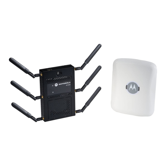
Verify that cable lengths are within the maximum allowable distances for optimal signal transmission. 1.4 AP650 Package Contents The AP650 model Access Point comes in four configurations, two Integrated Antenna models and two External Antenna models. The contents of the package differ between the Integrated Antenna model and the External Antenna model. -
Page 6: Features
• Lock port for Kensington® style Security Lock The AP650 access point has one RJ-45 connector supporting an 10/100/1000 Ethernet port and requires 802.3af-compliant power from an external source. When operating in a Gigabit Ethernet environment CAT-5e or CAT-6 cable NOTE is required for Gigabit operation. -
Page 7: Hardware Installation
Hardware Installation 2.1 Installation Instructions The AP650 Access Point mounts either on a wall with wide-shoulder screws or on a suspended ceiling T-bar. This unit is not designed for mounting on a desk. To prepare for installation, perform the following steps: 1. -
Page 8: Access Point Placement
This mounting requires hanging the AP650 Access Point along its width or length using the two slots on the bottom of the unit. The AP650 can be mounted on to any plaster, wood, or cement wall surface using the provided wall anchors when necessary. -
Page 9: Wall Mount Procedure
1. Orient the case on the wall by its width or length. Incorrect Orientation Correct Orientation To ensure proper operation of the AP650 Access Point ensure that the CAUTION thin Access Point is mounted in the correct orientation as shown above. - Page 10 AP650 Access Point 3. At each point, drill a hole in the wall, insert an anchor, screw into the anchor the wall mounting screw and stop when there is 1mm between the screw head and the wall. When pre-drilling a hole the recommended hole size is 2.8mm (0.11in.) if NOTE the screws are going directly into the wall and 6mm (0.23in.) if the...
-
Page 11: Integrated Antenna Model Suspended Ceiling T-Bar Mount Instructions
2.6 External Antenna Model Wall Mount Instructions Wall mounting requires hanging the AP650 access point along its width or length using the pair of slots on the bottom of the unit. The AP650 can be mounted onto any plaster, wood, or cement wall surface using the provided wall anchors when necessary. -
Page 12: Wall Mount Procedure
AP650 Access Point • Safety wire (recommended) and security cable (optional) In the event that the original mounting screws are lost, the following NOTE screws can be used instead: (ANSI Standard) #6-18 X 0.875in. Type A or AB Self-Tapping Screw, or (ANSI Standard Metric) M3.5 X 0.6 X 20mm Type D Self-Tapping Screw. -
Page 13: External Antenna Model Suspended Ceiling Tile (Plenum) Mount Instructions
2.7 External Antenna Model Suspended Ceiling Tile (Plenum) Mount Instructions Ceiling mount requires placing the AP650 access point above a suspended ceiling and installing the provided light pipe for viewing the status lights of the unit. Notes or warnings about suspended ceiling mounts apply to all NOTE installations where the unit is placed on suspended ceiling tile. -
Page 14: Ceiling Mount Procedure
AP650 Access Point 2.7.2 Ceiling Mount Procedure Light Pipe Ceiling Tile Badge 1. If possible, remove the ceiling tile from its frame and place it, finished side down, on a work surface. 2. If required, install a safety wire, between 1.5mm (.06in.) and 2.5mm (.10in.) in diameter, in the ceiling space. -
Page 15: Ap650 External Antenna Model Antenna Options
2.8 AP650 External Antenna Model Antenna Options Motorola supports two antenna suites for AP650 External Antenna models. One antenna suite supporting the 2.4 GHz band and another antenna suite supporting the 5 GHz band. Select an antenna model best suited to the intended operational environment of your Access Point. -
Page 16: Led Indicators
AP650 Access Point 2.9 LED Indicators Both the Integrated Antenna model and the External Antenna model have LED activity indicators on the front of the case for use with wall mount. With the External Antenna model unit mounted above a ceiling, LEDs are at the center of an oval badge on the ceiling;... -
Page 17: Installation Guide
Installation Guide 5 GHz Activity LED 2.4 GHz Activity LED Task (Amber) (Green) Firmware Upgrade Solid Sensor Mode (Connected to server) Blink (On 1 second, Off 1 second) Sensor Mode (Not connected to server) Blink (On 1 second, Off 5 seconds) -
Page 18: Specifications
AP650 Access Point Specifications 3.1 AP650 External Antenna Model Electrical Characteristics An AP650 External Antenna model Access Point has the following electrical characteristics: Operating Current & 180mA- 270mA @ 48VDC Voltage 3.2 AP650 External Antenna Model Physical Characteristics An AP650 External Antenna model Access Point has the following physical characteristics: Dimensions 8.50 in. -
Page 19: Ap650 Integrated Antenna Model Electrical Characteristics
180mA- 270mA @ 48VDC Voltage 3.4 AP650 Integrated Antenna Model Physical Characteristics An AP650 Integrated Antenna model Access Point has the following physical characteristics: Dimensions 9.50 in. Depth x 7.5 in. Width x 1.9 in. Height 24.13 cm Depth x 19.05 cm Width x 4.83 cm Height... -
Page 20: Radio Characteristics
AP650 Access Point 3.5 Radio Characteristics An AP650 model Access Point has the following radio characteristics: Operating Channels All channels from 4920 MHz to 5825 MHz except channel 52 -64 Channels 1-13 (2412-2472 MHz) Channel 14 (2484 MHz) Japan only Actual operating frequencies depend on regulatory approval for the country of use. -
Page 21: Regulatory Information
Motorola, Inc. (“Motorola”). This guide applies to Model Number AP-650 All Motorola/Symbol devices are designed to be compliant with rules and regulations in locations they are sold and will be labeled as required. Local language translations are available at the following website: http://supportcentral.motorola.com/... -
Page 22: Frequency Of Operation - Fcc And Ic
AP650 Access Point 4.1.2 Frequency of Operation – FCC and IC 5 GHz Only The use on UNII (Unlicensed National Information Infrastructure) Band 1 5150-5250 MHz and Band 3 5470 - 5725 MHz is restricted to indoor use only, any other use will make the operation of this device illegal. -
Page 23: Rf Exposure Guidelines
The device complies with internationally recognized standards covering human exposure to electromagnetic fields from radio devices. For information on “International” human exposure to eletromagnic fields refer to the Motorola/Symbol Declaration of Conformity (DoC) at http://www.motorola.com/doc. 4.5 EU Remote and Standalone Antenna Configurations... -
Page 24: Radio Frequency Interference Requirements-Fcc
AP650 Access Point 4.8 Radio Frequency Interference Requirements—FCC This equipment has been tested and found to comply with the limits for a Class B digital device, pursuant to Part 15 of the FCC rules. These limits are designed to provide reasonable protection against harmful interference in a residential installation. -
Page 25: Ce Marking And European Economic Area (Eea)
• Italy requires a user license for outside usage. 4.11 Statement of Compliance Motorola/Symbol hereby, declares that this device is in compliance with the essential requirements and other relevant provisions of Directive 1999/5/EC. A Declaration of Conformity may be obtained from... -
Page 26: Waste Electrical And Electronic Equipment (Weee)
AP650 Access Point 4.12 Waste Electrical and Electronic Equipment (WEEE) English: For EU Customers: All products at the end of their life must be returned to Motorola for recycling. For information on how to return product, please go to: http://www.motorola.com/recycling/weee. -
Page 27: Turkish Weee Statement Of Compliance
Suomi: Asiakkaat Euroopan unionin alueella: Kaikki tuotteet on palautettava kierrätettäväksi Motorola-yhtiöön, kun tuotetta ei enää käytetä. Lisätietoja tuotteen palauttamisesta on osoitteessa http://www.motorola.com/recycling/weee. Dansk: Til kunder i EU: Alle produkter skal returneres til Motorola til recirkulering, når de er udtjent. Læs oplysningerne om returnering af produkter på: http://www.motorola.com/recycling/weee. -
Page 28: Japan (Vcci) - Voluntary Control Council For Interference Class B Ite
AP650 Access Point 4.14 Japan (VCCI) - Voluntary Control Council for Interference Class B ITE この装置は、情報処理装置等電波障害自主規制協議会 (VCCI)の基準に基づくク ラス B 情報技術装置です。この装置は、家庭環境で使用することを目的としています が、この装置がラジオやテレビジョン受信機に近接して使用されると、受信障害を引 き起こすことがあります。 取扱説明書に従って正しい取り扱いをして下さい。 This is a Class B product based on the standard of the Voluntary Control Council for Interference from Information Technology Equipment (VCCI). -
Page 29: Chile
Installation Guide 4.16.3 Chile “Este equipo cumple con la Resolución No 403 de 2008, de la Subsecretaria de telecomunicaciones, relativa a radiaciones electromagnéticas.”. "This device complies with the Resolution Not 403 of 2008, of the Undersecretary of telecommunications, relating to electromagnetic radiation.” 4.16.4 Mexico Restrict Frequency Range to: 2.450 –... -
Page 30: Korea
AP650 Access Point The low power radio-frequency devices must be susceptible with the interference from legal communications or ISM radio wave radiated devices. 臺灣 低功率電波輻射性電機管理辦法 第十二條 經型式認證合格之低功率射頻電機,非經許可,公司、商號或使用者均不得擅自 變更頻率、加大功率或變更原設計之特性及功能。 第十四條 低功率射頻電機之使用不得影響飛航安全及干擾合法通信;經發現有干擾現象 時,應立即停用,並改善至無干擾時方得繼續使用。 前項合法通信,指依電信規定作業之無線電通信。 低功率射頻電機須忍受合法通信或工業、科學及醫療用電波輻射性電機設備之干 擾。 Wireless device operate in the frequency band of 5.25-5.35 GHz, limited for Indoor use only. -
Page 31: Customer Support
• Model number or product name • Software type and version number Motorola Solutions responds to calls by email or telephone within the time limits set forth in support agreements. If you purchased your Enterprise Mobility business product from a Motorola Solutions business partner, contact that business partner for support. -
Page 32: Ap-650 Access Point China Rohs Compliance
(Cd) (Parts) (PBB) (PBDE) (Metal Parts) (Circuit Modules) (Cables and Cable Assemblies) (Plastic and Polymeric Parts) (Optics and Optical Components) (Batteries) SJ/T11363-2006 SJ/T11363-2006 This table was created to comply with China RoHS requirements for Motorola Solutions‘ AP-650 model Access Points. - Page 33 Installation Guide...
- Page 34 AP650 Access Point...
- Page 35 Installation Guide...
- Page 36 Schaumburg, IL 60196-1078, U.S.A. http://www.motorolasolutions.com MOTOROLA, MOTO, MOTOROLA SOLUTIONS and the Stylized M Logo are trademarks or registered trademarks of Motorola Trademark Holdings, LLC and are used under license. All other trademarks are the property of their respective owners. © 2012 Motorola Solutions, Inc. All Rights Reserved.