Table of Contents
Advertisement
Advertisement
Table of Contents

Related Manuals for Eurotherm Invensys 2408


Summary of Contents for Eurotherm Invensys 2408
- Page 1 CONTROL SETPOINT PROGRAMMER Installation and operation handbook...
- Page 2 “This product is covered by one or more of the following US Patents: 5,484,206; Additional patents pending. PDS and INSTANT ACCURACY are trademarks of Eurotherm.” Issue 10 of this handbook applies to software version 4. Issue 10.0 Nov-04 Applies to 2408 and 2404 controller software version 4.0...
- Page 3 DeviceNet Communications Handbook part no. HA027506 which includes the parameter address map. • Profibus Communications Handbook part no. HA026290 • EMC (Electromagnetic Compatibility) Installation Guide, part no. HA025464 These are available on www. eurotherm.co.uk. Issue 10.0 Nov-04 Applies to 2408 and 2404 controller software version 4.0...
-
Page 4: Chapter 1 Installation
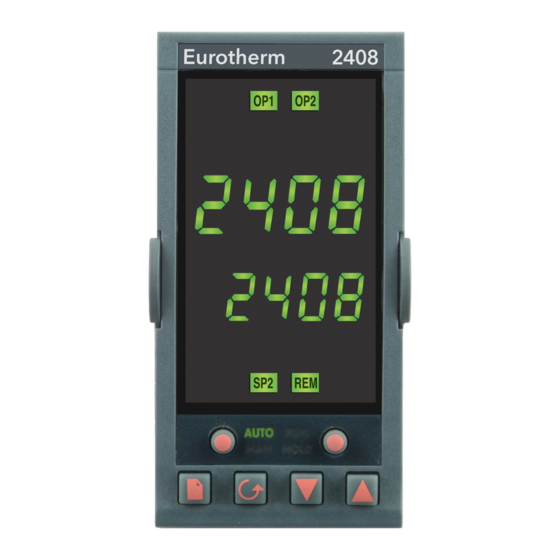
Chapter 1 INSTALLATION Terminal covers Sleeve Ratchets Display screen Label Panel retaining clips Latching ears Panel sealing gasket Figure 1-1 2408 1/8 DIN controller Sleeve Terminal covers Ratchets Display screen Label Panel retaining clips Latching ears Panel sealing gasket Figure 1-2 2404 1/4 DIN controller... - Page 5 OP 1 OP2 cut-out 92 x 45mm 96mm 3.78in +0.8 +0.6 3.62x1.77in +0.03 +0.02 AUTO HOLD Figure 1-3 Outline dimensions of Model 2408 controller 10mm 38mm (0.4in) (1.5in) Recommended minimum spacing (Not to of controllers scale Outline dimensions Model 2404 150mm 96mm 5.91in...
-
Page 6: Mechanical Installation
Installation INTRODUCTION Models 2408 and 2404 are high stability, temperature or process controllers with self and adaptive tuning. They have a modular hardware construction which accepts up to three plug- in Input/Output modules and two interface modules to satisfy a wide range of control requirements. - Page 7 Installation and Operation Handbook NEW SLEEVE DESIGN MKIII From Jan-03 an improved design of 1/8 DIN long sleeve is shipped with all new 2408 controllers and indicators. (The month and year of manufacture are shown in the last two pairs of digits of the instrument serial number).
-
Page 8: Electrical Installation
− − Figure 1-5 Rear terminal layout − Model 2408 * The ground connection is provided as a return for internal EMC filters. It is not required for safety purposes, but must be connected in order to satisfy EMC requirements. - Page 9 20 − 29Vac/dc Low voltage supply Model 2404 rear terminal layout Ground Line 85 to 264Vac Neutral Ground* Input 1 Input 2 Common Alarm relay RTD/Pt100 − − Figure 1-6 Rear terminal layout − Model 2404 2408 and 2404 Controller...
- Page 10 PDS 1 mode uses a logic output module to control aTE10S solid state relay and provides a load failure alarm. PDS 2 mode uses a logic output module to control a TE10S solid state relay, provide load/SSR failure alarms, and read back the load current for display on the controller. 2408 and 2404 Controller...
- Page 11 (BUT NOT THE TRIAC) by breaking the PCB track that runs crosswise, adjacent to the edge connectors of the module. This can be done by inserting the blade of a small screwdriver into one of the two slots that bound it, and twisting. 2408 and 2404 Controller...
- Page 12 Triple logic input and output modules - see ratings on the next page Triple contact input Input 1 Input 2 Input 3 Common Triple logic input Input 1 Input 2 Input 3 Common Triple logic output Output 1 Output 2 Output 3 Common Program events 2408 and 2404 Controller...
- Page 13 >28KΩ input resistance OFF state voltage >14Vdc ON state <100Ω resistance ON state voltage <1.0Vdc Triple logic output (current sourcing) OFF state output 0 to 0.7Vdc. ON state output 12 to 13Vdc, at up to 8mA. 1-10 2408 and 2404 Controller...
- Page 14 Installation COMMUNICATION MODULES 1 AND 2 All 2408 and 2404 controllers can be fitted with up to two plug-in communications modules. Only one of the two modules can be for serial communications and this will normally be installed in position COMMS 1 (although it is possible to install the serial communications module in position COMMS 2.
- Page 15 All resistors are 220 ohm 1/4W carbon composition. Local grounds are at equipotential. Where equipotential is not available wire into separate zones using a galvanic isolator. Use a repeater (KD845) for more than 32 units. Figure 1-9 EIA-485 wiring 1-12 2408 and 2404 Controller...
- Page 16 • 2 fuses or circuit breakers to protect the bus from excessive current which could damage the cable and connectors. • The earth connection, HF, to be connected to the main supply earth terminal. 2408 and 2404 Controller 1-13...
- Page 17 2400 Controller Network Supply 24Vdc ( +1%) 250mV p-p Ripple (SLAVE) Address N+1 * Fit 121! resistor to last instrument in the chain Daisy chain to further instruments To configure DeviceNet Communications see Chapter 6. 1-14 2408 and 2404 Controller...
- Page 18 Controllers supplied with model numbers 2408f and 2404f are fitted with ProfiBus communications modules fitted in the H slot. Further details of ProfiBus communications is given in Appendix E and the ProfiBus Communications handbook part number HA026290. This handbook can be downloaded from www.eurotherm.co.uk. Station 1 Not connected...
-
Page 19: Typical Wiring Diagram
1A(T) Logic heating output Triac cooling output Heating power fuse (load dependent) − Solid State Relay * Heater Cooling Solenoid Fig 1-10 Typical wiring diagram, Model 2408 Controller For logic drive capability see following chart:- 1-16 2408 and 2404 Controller... - Page 20 TC1027 TE200S TC2000 RS3D Standard Multi- Logic V Logic Logic Logic drive Logic 2S 3P 1S2P 6S 1P 3S 3P 3S 3P 3S 1P 4S 2P Triple 4S 1P 2S 1P 2S 1P logic 2408 and 2404 Controller 1-17...
- Page 21 + + + + RTD/Pt100 + + + + Input + + + + Motor Module Feedback Potentiometer − − − − − − − − − − − − (Optional) Fig 1-11 Motorised valve connections 1-18 2408 and 2404 Controller...
- Page 22 This chapter has nine topics: • FRONT PANEL LAYOUTS • BASIC OPERATION • OPERATING MODES • AUTOMATIC MODE • MANUAL MODE • PARAMETERS AND HOW TO ACCESS THEM • NAVIGATION DIAGRAM • PARAMETER TABLES • ALARMS 2408 and 2404 Controller...
- Page 23 Run/Hold HOLD Manual mode Program in Hold Page Scroll Down Button Button Button Button Figure 2-1 Model 2408 front panel layout 2404 2404 Output 2 Output 1 OP 1 OP 2 OP 1 Upper readout Lower readout Remote setpoint/ Setpoint 2...
- Page 24 Press to select a new parameter in a list. Down button Press to decrease a value in the lower readout. Up button Press to increase a value in lower readout. Figure 2-3 Controller buttons and indicators 2408 and 2404 Controller...
-
Page 25: Basic Operation
If the controller detects an alarm condition, it flashes an alarm message in the Home display. For a list of all the alarm messages, their meaning and what to do about them, see Alarms at the end of this chapter. 2408 and 2404 Controller... -
Page 26: Operating Modes
Two other modes are also available: • Remote Setpoint mode, in which the setpoint is generated from an external source. In this mode, the REM light will be on. • Programmer mode which is explained in Chapter 5, Programmer Operation. 2408 and 2404 Controller... -
Page 27: Automatic Mode
Output Power display may access further parameters. These may be in this scroll list if the ‘Promote’ feature has been used (see Chapter 3, Edit Level). When you reach the end of this scroll list, pressing will return you to the Home display. 2408 and 2404 Controller... -
Page 28: Manual Mode
Output Power display may access further parameters. These may be in this scroll list if the ‘Promote’ feature has been used (see Chapter 3, Edit Level). When you reach the end of this scroll list, pressing will return you to the Home display. 2408 and 2404 Controller... - Page 29 When you reach the end of the list, you will return to the list header. From within a list you can return to the current list header at any time can by pressing To step to the next list header, press once again. 2408 and 2404 Controller...
- Page 30 . During adjustment, single presses change the value by one digit. Keeping the button pressed speeds up the rate of change. Two seconds after releasing either button, the display blinks to show that the controller has accepted the new value. 2408 and 2404 Controller...
- Page 31 Auto PrG.t 35.0 rEL.C Lb t rEL.2 1.00 1.00 FASt rAtE diAG FF.Pb out.n SEG.n FF.tr ti.2 SEG.n SYnc tYPE FF.dv td.2 tYPE 100.0 50.0 dwEl SEG.d tYPE dwEl Figure 2-7a Navigation diagram (Part A) 2-10 2408 and 2404 Controller...
- Page 32 The shaded boxes are normally hidden in Operator level. To see all the available parameters you must select Full level. SP H See Chapter 3, Access Levels. 100.0 Figure 2-7b Navigation diagram (Part B) For additional parameters - see tables 2408 and 2404 Controller 2-11...
- Page 33 Event output states (OFF / on) (not 8-segment programmer) SYnc SYnc SYnc SYnc Segment synchronisation (no / YES) (not 8-segment programmer) SEG.d SEG.d SEG.d SEG.d Flash active segment type in the lower readout of the home display (no / YES) 2-12 2408 and 2404 Controller...
- Page 34 Event output: OFF/on (not 8-segment programmer) Segment synchronisation: no/YES SYnc SYnc SYnc SYnc (not 8-seg progr) End of prog − dwEl, RSEt, S OP End.t End.t End.t End.t Power level in end segment 2408 and 2404 Controller 2-13...
- Page 35 One-shot autotune enable U.br Valve sensor break strategy Adaptive tune enable drA.t drA.t drA.t drA.t Adaptive tune trigger level in display units. Range = 1 to 9999 Automatic Droop Compensation (PD control only) 2-14 2408 and 2404 Controller...
- Page 36 PV = ip.2 above ‘Hi.Ip’ Derived function, (if configured) PV = (f.1 x iP1) + (f.2 x iP2). ‘F.1’ and ‘F.2’ are scalars with the range -9.99 to 10.00 PV.ip Selects ‘ip.1’ or ‘ip.2’ Continued in next column 2408 and 2404 Controller 2-15...
- Page 37 Network connected but not PID output to motorised valve operational oFF.L Network not connected ACCS ACCS ACCS ACCS Access List codE Access password Goto Goto level - OPEr, FuLL, Edit or conF ConF Configuration password 2-16 2408 and 2404 Controller...
- Page 38 _HSP* 4rAt Load Current High alarm PV Rate of change alarm _HCr* Always assigned to Alarm 4 * In place of the dash, the first character will indicate the alarm number. Table 2-1 Process alarms 2408 and 2404 Controller 2-17...
- Page 39 Indicates that the PDS input is short circuit Circuit Mode 5 only Hw.Er Hw.Er Hw.Er Hw.Er Hardware error Check that the correct modules are fitted. Indication that a module is of the wrong type, missing, or faulty. 2-18 2408 and 2404 Controller...
- Page 40 Acknowledge by pressing ‘page’ key two hours and ‘scroll’ key together P.br P.br P.br P.br Potentiometer break Check that the feedback potentiometer is correctly connected or the pot is not open circuit Table 2-2 Diagnostic alarms 2408 and 2404 Controller 2-19...
- Page 41 Operation Installation and Operation Handbook 2-20 2408 and 2404 Controller...
- Page 42 (See Edit level at the end of this chapter). conF Configuration This special level allows access to set up the fundamental characteristics of the controller. Figure 3-1 Access levels 2408 and 2404 Controller...
- Page 43 If no button is pressed for ten seconds, you will be returned to the Home display. Alternatively, pressing together takes you immediately back to the Home display. 2408 and 2404 Controller...
- Page 44 To return to operator level from either ‘FuLL’ or ‘Edit’ level, repeat entry of the password and select ‘OPEr’ on the ‘Goto’ display. In ‘Edit’ level, the controller will automatically return to operator level if no button is pressed for 45 seconds. 2408 and 2404 Controller...
- Page 45 A maximum of twelve parameters can be promoted. Promoted parameters are automatically ‘alterable’. Please note, in the ‘PrOG List’, the parameters from segment number (SEG.n) onwards cannot be promoted. 2408 and 2404 Controller...
- Page 46 Relative cool Only present if cooling has been configured and a module is fitted. Sets the cooling proportional band, which equals the Pb gain value divided by the rEL value. Table 4-1 Tuning parameters 2408 and 2404 Controller...
- Page 47 Tuning Installation and Operation Handbook AUTOMATIC TUNING Two automatic tuning methods are provided in the 2408 and 2404: • A one-shot tuner, which automatically sets up the initial values of the parameters listed in Table 4-1 on the previous page.
- Page 48 Adaptive tune should not be used: 1. Where the process is subjected to regular external disturbances that could mislead the adaptive tuner. 2. On highly interactive multiloop applications. However, moderately interactive loops, such as multi-zone extruders, should not give a problem. 2408 and 2404 Controller...
- Page 49 5. Set the Pb, ti, td parameter values according to the calculations given in Table 4-2. Type of control Proportional Integral time ‘ti’ Derivative time band ‘Pb’ ‘td’ Proportional only P + I control 2.2xB 0.8xT P + I + D control 1.7xB 0.5xT 0.12xT Table 4-2 Tuning values 2408 and 2404 Controller...
- Page 50 In example (a) increase ‘Lcb’ by the overshoot value. In example (b) reduce ‘Lcb’ by the undershoot value. Example (a) Temperature Setpoint Overshoot Example (b) Temperature Setpoint Undershoot Time Where the temperature approaches setpoint from above, you can set ‘Hcb’ in a similar manner. 2408 and 2404 Controller...
- Page 51 The display shows tU.Er - Tune Error. This alarm could occur if: 1. The process to be tuned has a very slow response time 2. The sensor has failed or is incorrectly aligned 3. The loop is broken or not responding correctly 2408 and 2404 Controller...
- Page 52 Installation and Operation Handbook Tuning MOTORISED VALVE CONTROL The 2408 and 2404 can be configured for motorised valve control as an alternative to the standard PID control algorithm. This algorithm is designed specifically for positioning motorised valves. These are ordered pre-configured as Model numbers: •...
- Page 53 1. In Operator level, press the AUTO/MAN button to put the controller in Manual mode. 2. Drive the valve to its fully open position using 3. Press until you get to ‘ip-List’. 4. Press to get to ‘PCAL-OFF’. 2408 and 2404 Controller...
- Page 54 21. Calibration is complete when the display returns to ‘GO-no’. 22. Press together to return directly to the Operator level. 23. Press the AUTO/MAN button to place the controller in AUTO and the calibration of the position feedback potentiometer is now complete. 2408 and 2404 Controller...
- Page 55 The 2408 and 2404 has two sets of PID values. You can select the active set from either a digital input, or from a parameter in the PID list, or you can transfer automatically in gain scheduling mode.
- Page 56 Programmer Operation Chapter 5 PROGRAMMER OPERATION This chapter deals with the setpoint programming option. All 2408 / 2404 instruments have a basic 8-segment programmer built-in as standard. This facility must be enabled by the user, as explained in the section, Configuring the Programmer.
- Page 57 WHAT IS SETPOINT PROGRAMMING? Many applications need to vary temperature, or process value, with time. Such applications need a controller which varies a setpoint as a function of time; all 2408 and 2404 models can do this. The setpoint is varied by using a setpoint program. Within each 2408 and 2404 controller, there is a software module called the programmer, which stores one, or more, such programs and drives the setpoint according to the selected program.
- Page 58 (see the final topic in this chapter). When the program ends, the programmer is put into either, a continuous Dwell state with all outputs staying unchanged, or the Reset state, or to a settable power level. Table 5-1 Segment Types 2408 and 2404 Controller...
- Page 59 Holdback will also occur if the PDSIO output is open circuit. This can be disabled in configuration by selecting the PdS output as SP.nH - ‘setpoint retransmission without holdback’ The program is complete. RUN light flashes Table 5-2 Program States 2408 and 2404 Controller...
- Page 60 ‘hoLd’. Such changes remain active only for the duration of the segment; the segment parameters will revert to their original (stored) values whenever the segment is re-executed. 2408 and 2404 Controller...
- Page 61 There are four different Holdback types. The choice of type is made by setting a parameter when creating a program, and may be one of the following:− ‘OFF’ − Disables Holdback − therefore no action is taken. 2408 and 2404 Controller...
- Page 62 Servo to new PV level Time Time Ramp Ramp Segment Segment Dwell Segment Figure 5-2 Continue after a power fail Figure 5-3 Ramp back after a power fail If ‘rSEt’ is selected, then when power is restored the program terminates. 2408 and 2404 Controller...
- Page 63 Four stored programs • Twenty stored programs Press Holdback Strategy to select: • Holdback type to be set in each segment • ProG Holdback type to be set for the whole program Press Continued on the next page. 2408 and 2404 Controller...
- Page 64 Event Outputs (not in 8-segment programmer) to select: • Event outputs disabled • Event outputs enabled Press Synchronisation (not in 8-segment programmer) to select: • Synchronisation disabled • Synchronisation enabled Press to return the list header. 2408 and 2404 Controller...
- Page 65 - see Chapter 6, Configuration. To invoke this mode of operation, the parameter ‘bcd’ in ‘inst-Conf’ must be set to ‘PrOg’. until you reach ‘bcd’. Press Use the buttons, to select ‘PrOG’. PrOG 5-10 2408 and 2404 Controller...
- Page 66 • Deviation High Holdback • bAnd Deviation Band Holdback Press Holdback value Note! The value set in this parameter is always for the whole program. to set the value. Press Continued on the next page. 2408 and 2404 Controller 5-11...
- Page 67 The parameters that follow ‘SEG.n’ set up the characteristics of the individually-selected segment number. By defining the characteristics of each segment of the program, you define the whole program. Press Continued on the next page. 5-12 2408 and 2404 Controller...
- Page 68 • Deviation Low Holdback • Deviation High Holdback • bAnd Deviation Band Holdback Press Target setpoint Target setpoint for ‘rmP.r’, ‘rmP.t’ or ‘StEP’ segments. Set the target setpoint using Press Continued on the next page. 2408 and 2404 Controller 5-13...
- Page 69 Number of cycles of the cALLed program Only appears for ‘cALL’ segments. (multi-program controllers only) Sets the number of cycles of the cALLed program from 1 to 999, using Press Continued on the next page. 5-14 2408 and 2404 Controller...
- Page 70 Synchronisation Disabled Note: This event output, if used, occupies the position of ‘out8’. Press End segment to select: • dwEl An indefinite dwell • rSEt Reset. • S OP End Segment Output Power Level Press 2408 and 2404 Controller 5-15...
- Page 71 Note: In programmer/controller software versions 3.56 onwards this parameter has been replaced by a parameter End.P End.P which appears at the end of the Output List, see End.P End.P Chapter 2 to return to the ProG-LiSt header. Press 5-16 2408 and 2404 Controller...
-
Page 72: Chapter 6 Configuration
Incorrect configuration could result in damage to the process being controlled and/or personal injury. It is the responsibility of the person commissioning the process to ensure that the configuration is correct. 2408 and 2404 Controller... - Page 73 ‘locked’ then pressing at this point will take you to the ‘Exit’ display with ‘no’ in the lower to return to the ‘ConF’ readout. Simply press display.) You will obtain the first display of configuration. 2408 and 2404 Controller...
- Page 74 There are TWO passwords. These are stored in the Password configuration list and can be selected and changed in the same manner as any other configuration parameter. The password names are: ‘ACC.P’ which protects access to Full level and Edit level ‘cnF.P’ which protects access to Configuration level. 2408 and 2404 Controller...
- Page 75 1200 rmP.U Ltch inp.H PSEc diSA 50.0 bLoc dtYP VaL.L SYnc nonE VaL.H diSA 100.0 PwrF Ltch Fwd.t bLoc nonE Pd.tr Sbr.t Ltch Sb.OP bLoc nonE Fig 6.1a Navigation Diagram (Part A) GSch 2408 and 2404 Controller...
- Page 76 ‘mV.C’, or ‘mA.C’, or ‘V.C’. The navigation diagram shows typical parameters, but is dependant upon the exact Fig 6.1b Navigation Diagram (Part B) configuration of the instrument. The following sheets show the full list of parameters. 2408 and 2404 Controller...
- Page 77 Configuration Installation and Operation Handbook NAVIGATION DIAGRAM (PART C) Calibration Password Config Config PASS Exit ConF ConF ACC.P nonE cnF.P UCAL pt1.L pt1.H OF1.L OF1.H pt2.L pt2.H OF2.L OF2.H Fig 6.1c Navigation Diagram (Part C) 2408 and 2404 Controller...
- Page 78 Manual mode Step Steps to forced output level. Value set in ‘FOP’ of ‘op-List’ in Operator Level none BCD input function Not used prog Select program number Select setpoint number gsch Gain schedule enable Disabled Enabled 2408 and 2404 Controller...
- Page 79 If a decimal point was configured, negative display and setpoint ranges were limited to -99.9 in previous software versions. The range has been increased to -199.9 by combining the negative sign with the figure one. This allows Setpoints, Process Variables, Alarm Setpoints and Programmers to be set to -199.9. 2408 and 2404 Controller...
- Page 80 Linear Input Scaling − The next 4 parameters only appear if a linear or sq rt input is chosen. Displayed Value inp.L Input value low VAL. H inp.H Input value high VAL.L Displayed reading low VAL. L Electrical VAL.H Input Displayed reading high inP.L inP.H 2408 and 2404 Controller...
- Page 81 Local setpoint tracks programmer SP rmP.U PSEc Setpoint rate limit units Per second Pmin Per minute Per hour Remote setpoint configuration nonE Disable Remote setpoint Loc.t Remote setpoint + local trim rmt.t Remote trim + local setpoint 6-10 2408 and 2404 Controller...
- Page 82 Evnt’ means that the alarm is used to trip an external event. If this option is selected the front panel alarm message will not appear. ‘mAn’ means that the alarm will be latched, and can only be reset after it has first cleared (called ‘manual reset mode’). 2408 and 2404 Controller 6-11...
- Page 83 Reset the program Srvo to.PV Starting setpoint of a From the Process Value (PV) to.SP program (Servo point) From the setpoint Programmable event Disabled outputs Enabled SYNC Synchronisation of programs Disabled of several programmers Enabled 6-12 2408 and 2404 Controller...
- Page 84 Standby - ALL control outputs turned OFF (alarm Outputs are not affected) PV.SL PV Select: Closed = PV1 / Open = PV2 Advance to End of Segment and to Target Setpoint PrGn Program number AmPS Current – LB only 2408 and 2404 Controller 6-13...
- Page 85 YES / no Programmer event output active, where ‘n’ = event number from 1 to 8. (Not available with 8-segment programmer.) Digital Events SEnS Output Module Figure 6-2 Combining several digital events on to one output 6-14 2408 and 2404 Controller...
- Page 86 PDS PV retransmission OP.oP PDS output power retransmission Er.OP PDS error signal retransmission SP.nH PDS setpoint retransmission - no holdback Output Scaling Displayed Value VAL.L Retransmitted value low VAL.H VAL.H Retransmitted Value High Retransmitted VAL.L Output 100% 2408 and 2404 Controller 6-15...
- Page 87 Electrical Input 100% Note: Having configured the module function as remote setpoint you must then specify the type of remote setpoint in the SP-conf list Comms 2 module config As per Comms 1 module configuration 6-16 2408 and 2404 Controller...
- Page 88 = 10V A Transducer Power Supply does not provide any calibration facility and is simply a 5 or 10V power supply. To invert a PID output, the Val. H can be set below the Val.L 2408 and 2404 Controller 6-17...
- Page 89 Remote OP power max. rOP.L Remote OP power min. VPoS Motorised valve position VAL.L Displayed value low Displayed value equivalent to 0% potentiometer position VAL.H VAL.H Displayed value high equivalent to 100% potentiometer position Potentiometer VAL.L position 100% 6-18 2408 and 2404 Controller...
- Page 90 Linear Input Scaling − The next four parameters only appear if a linear input is chosen. Displayed Value inP.L Input value low VAL.H inP.H Input value high VAL.L Displayed value low VAL.L Electrical VAL.H Displayed value high Input inP.L inP.H 2408 and 2404 Controller 6-19...
- Page 91 Linearisation Value representing in 8 Note: Custom Linearisation is only available when ‘3a-Conf’or iP- ConF list has ‘inpt’ set to ‘mV.C’, or ‘mA.C’, or ‘V.C’. 2. The values and inputs must be continuously increasing or decreasing 6-20 2408 and 2404 Controller...
- Page 92 Note. When a DC input module is installed for the first time, or there is a requirement to change one, then the microprocessor in the controller needs to read the factory calibration data stored in the module. Select ‘FACt’ as the calibration value. Step to ‘GO’ and start calibration. 2408 and 2404 Controller 6-21...
- Page 93 PASS PASS PASS Password configuration ACC.P FuLL or Edit level password cnF.P Configuration level password Note:- When passwords are changed please make a note of the new numbers Exit Exit Exit Exit no/YES Exit configuration 6-22 2408 and 2404 Controller...
-
Page 94: Configuration Examples
= 5Vdc Press (twice) to SEnS read ‘Sens’ The Transducer Power supply uses existing software Press written for digital modules. A select ‘inv’ or ‘nor’ list of parameters follow which are not applicable to this module. 2408 and 2404 Controller 6-23... - Page 95 FuLL - the decimal point Press to read position is implied, eg 100.1 ‘rES’ is transmitted as 1001. Press FuLL ‘int’ - rounded to the select ‘FuLL’ or ‘int’ nearest integer value 6-24 2408 and 2404 Controller...
- Page 96 Addr ‘Addr’ 10. Press select the address Indicates the network status:- 11. Press to read ‘nw.St’ ‘run’ = network connected nw.St and operational ‘rdy’ = network connected but not operational ‘OFF.L’ = network not connected 2408 and 2404 Controller 6-25...
- Page 97 Configuration Installation and Operation Handbook 6-26 2408 and 2404 Controller...
- Page 98 Calibrate the controller to suit the characteristics of a particular installation. Remove long term drift in the factory set calibration. User calibration works by introducing a single point, or two-point, offset onto the factory set calibration. 2408 and 2404 Controller...
- Page 99 Press until you reach ‘UCAL’. User Calibration Enable UCAL to select: • YES: Calibration enable • Calibration disabled together to go to the Exit display. Press Exit configuration to select ‘YES’ to return to Operator level. 2408 and 2404 Controller...
- Page 100 ‘CAL’ display. Calibration type • FACt: Factory Calibration • USEr: User Calibration FACt to select ‘FACt’. Selecting ‘FACt’ reinstates the factory calibration and allows the application of a single fixed offset. Press continued on the next page 2408 and 2404 Controller...
- Page 101 ‘iP-LiSt’ header. To protect the calibration against unauthorised adjustment, return to Operator level and make sure that the calibration parameters are hidden. Parameters are hidden using the ‘Edit’ facility described in Chapter 3, Access Levels. 2408 and 2404 Controller...
- Page 102 ‘CAL’ display. Calibration type • FACt: Factory Calibration • USEr: User Calibration to select ‘USEr’. FACt Selecting ‘USEr’ enables two-point calibration. [If two-point calibration is unsatisfactory, select ‘FACt’ to return to the factory set calibration.] Press 2408 and 2404 Controller...
- Page 103 ‘ip-List’ header. To perform the High-point Calibration, repeat the above procedure, selecting ‘ip1.H’ in the ‘CAL.S’ display for adjustment. Press three times. Calibration type ‘USEr’ was selected for the Low-point Calibration, and has remained selected. USEr Press 2408 and 2404 Controller...
- Page 104 ‘Edit’ facility described in Chapter 3. To perform a User Calibration on Input 2, proceed as with Input 1 above, except that when ‘CAL.S-nonE’ appears, press until ‘CAL.S-iP2.L’ is obtained, then proceed as with Input 1. Repeat the procedure for ‘iP2.H’. 2408 and 2404 Controller...
- Page 105 Offset Low for Input 2 Calculated offset, in display units. OF2.H Offset High for Input 2 Calculated offset, in display units. Note: The value of each of the parameters in the above table may also be altered by using buttons. 2408 and 2404 Controller...
- Page 106 Appendix A UNDERSTANDING THE ORDERING CODE The 2408 and 2404 controllers have a modular hardware construction, which accepts up to three plug-in Input/Output modules and two communications modules to satisfy a wide range of control requirements. Two digital inputs and an optional alarm relay form part of the fixed hardware build.
- Page 107 Valve raise and lower Logic + relay Fitted unconfigured PID heat + PID cool Mode 2 + cool Logic + triac Fitted unconfigured PID heat + PID cool Mode 2 + cool Transducer P5 5Vdc 10Vdc 2408 and 2404 Controller...
- Page 108 Table A alarm options plus: German Transducer PSU Dutch Rate of change 5Vdc Spanish PDS alarms 10Vdc Heater break detect Swedish Current monitor heater brk Italian Current monitor SSR fail Program event 7 (note 7) Program END output 2408 and 2404 Controller...
- Page 109 32 to 3650 (Hoskins) W5%Re/W26%Re 10 to 2300 50 to 4172 (Englehard) W5%Re/W26%Re 0 to 2000 32 to 3632 (Bucose) Pt10%Rh/Pt40%Rh 200 to 1800 392 to 3272 Exergen K80 I.R. -45 to 650 -50 to 1200 pyrometer 2408 and 2404 Controller...
- Page 110 CTX (mode 5) (input 2 only) The example given in the coding is for 2408 PID controller, 85 to 264 Vac, logic heating, relay cooling, low alarm relay, high alarm relay, RS485 Modbus comms, PDSIO setpoint retransmission, type K thermocouple, 0 to 1000 C, Auto/manual select, second setpoint select, manual button disabled.
- Page 111 Sensor input table. For these inputs, the values entered here are the low and high setpoint limits. For process inputs, the values are the display scaling. corresponding to the minimum and maximum input values. 2408 and 2404 Controller...
- Page 112 EN 50081-2 and EN 50082-2. For more information on product compliance refer to the Technical Construction File. SERVICE AND REPAIR This controller has no user serviceable parts. Contact your nearest Eurotherm Controls agent for repair. Caution: Charged capacitors Before removing an instrument from its sleeve, disconnect the supply and wait at least two minutes to allow capacitors to discharge.
- Page 113 Due to RFI Filtering there is an earth leakage current of less than 0.5mA. This may affect the design of an installation of multiple controllers protected by Residual Current Device, (RCD) or Ground Fault Detector, (GFD) type circuit breakers. 2408 and 2404 Controller...
- Page 114 • the controller setpoint set too high. Where damage or injury is possible, we recommend fitting a separate over-temperature protection unit, with an independent temperature sensor, which will isolate the heating circuit. 2408 and 2404 Controller...
- Page 115 To ensure compliance with the European EMC directive certain installation precautions are necessary as follows: • For general guidance refer to Eurotherm Controls EMC Installation Guide, HA025464. • When using relay or triac outputs it may be necessary to fit a filter suitable for suppressing the emissions.
- Page 116 12Vdc, 8mA per channel (isolated) Digital o/p functions As per the ordering code High current output 10Amp, 264Vac resistive. This option is not available on controller from Jan-04 Triac rating 1A, 30 to 264Vac resistive (isolated) Analogue outputs 2408 and 2404 Controller...
- Page 117 RS232,2-wire,RS 485 and 4 wire RS485 modules Baud rate 1200, 2400, 4800, 9600 and 19,200 baud Slave input (isolated) Remote setpoint input with holdback to master Master output Isolated from main PV. Retransmission of setpoint, process value or output 2408 and 2404 Controller...
- Page 118 C and 5 to 90% RH non-condensing Storage temperature -10 to +70 Panel sealing IP65 Dimensions 2408: 48mm wide x 96mm high x 150mm deep 2404: 96mm wide x 96mm high x 150mm deep Weight 250g EMC standards EN61326-1 generic standards for industrial environments...
- Page 119 Technical Specification Installation and Operation Handbook 2408 and 2404 Controller...
- Page 120 DIAGNOSTICS Current flowing in a system of electrical heating elements (the ‘Load’) can be displayed on the controller by using a Eurotherm TE10 SSR fitted with intelligent current transformer, PDCTX, or an SSR or contactor with an external PDCTX. Load current monitoring and diagnostics may be used with any time proportioned output,...
- Page 121 2. Eurotherm intelligent current transformer type PD/CTX + contactor or zero voltage switching SSR 2408 or 2404 controller configured for PDS mode 2 option using logic output. This module must be fitted in module position 1. (order code M2). Controller...
- Page 122 1. Eurotherm intelligent current transformer type PD/CTX + contactor 2. 2408 or 2404 controller configured for PDS mode 5 option using logic, relay or triac output. This module must be fitted in module position 1. Digital input LB (order code M5) must be configured to accept PDCTX input as described in the configuration section of this appendix.
- Page 123 Meter mode applies to mode 5 only. If low current alarms are not configured the current displayed is a filtered instantaneous RMS value. This behaves like a damped analogue meter. It may be used in applications where the current sensor is not linked to control, for example, telemetry, indication. 2408 and 2404 Controller...
- Page 124 Ct.OP Current Indicates that the PDS input is open circuit. Transformer Mode 5 only Open Circuit Ct.Sh Current Indicates that the PDS input is short circuit Transformer Mode 5 only Short Circuit 2408 and 2404 Controller...
- Page 125 , such as control. Any one or more alarms can be attached to an output, which will operate when an alarm occurs. Contacts are rated at 2A 264Vac for operating external beacons or audible devices. 2408 and 2404 Controller...
- Page 126 SSr1 or is set to PDS mode SSr 2 as required. This is the lower PID Press to show VAL.L demand level VAL.L To set the minimum PID signal to 0% Press to show 0.0 2408 and 2404 Controller...
- Page 127 This is the maximum 100.0 output power Press To set the max output power to 100 to show 100.0 SenS Press to show This sets the output SEnS signal to normal for heating control Press to show nor 2408 and 2404 Controller...
- Page 128 Press to select AmPs The system is designed to operate in either mode 2 or mode 5 configuration only. Selecting both simultaneously will disable the output. However, mode 1 and mode 5 can be used together. 2408 and 2404 Controller...
- Page 129 To make alarm 2 = has been accepted High Current Press to show HCr Note:- The above alarms are known as SOFT ALARMS because they are indication only. D-10 2408 and 2404 Controller...
- Page 130 YES or output will not activate Repeat the above step for every alarm to be attached to the output Alarms Connected to a Relay Output Soft SEnS Alarms Output Module 2408 and 2404 Controller D-11...
- Page 131 Scalar = 100/N Where N = Turns through PDCTX Scalar Scalar Maximum Resolvable Current TE10 Determined by the maximum range of the SSR PDCTX 100A (or 100 ampere turns) Finally Exit configuration level. See Chapter 5. D-12 2408 and 2404 Controller...
- Page 132 Appendix E: Profibus Communications Introduction The 2408f and 2404f are special versions of the 2408 and 2404 controllers designed for Profibus-DP communications. The ‘standard’ 2408 or 2404 controllers cannot be upgraded to a 2408f or 2404f as the latter uses a different version of the microprocessor board.
-
Page 133: Technical Specification
2408f or 2404f controller Twisted pair Intermediate stations Last Station Not connected Shield VP (+5Vdc Voltage Potential) 390Ω B (Rx/Tx +ve) 220Ω A (Rx/Tx -ve) Last station only requires 390Ω DGND (Digital ground) terminating resistors 2408f or 2404f controller 2408 and 2404 Controller... - Page 134 400m 200m Type B cable 1200m 1200m 1200m 600m 200m Belden B3079A meets cable A specifications, but there are other choices. For more information refer to the ‘Profibus Product Guide’ produced by the Profibus User Group. 2408 and 2404 Controller...
- Page 135 From the HOME display, press LiSt Node address Addr Press to display the node address. Press to set the desired address. 0 -126 Comms Status Stat This is a read-only diagnostic display Ready to run Comms running 2408 and 2404 Controller...
- Page 136 How many parameters can I select? How many parameters can I select? Up to 117 per node, total of inputs and outputs. What can I run it on? What can I run it on? Windows 3.1, Windows 95, or Windows NT. 2408 and 2404 Controller...
- Page 137 Ensure that the last device (not necessarily a 2404/8) in the network segment is correctly terminated (see wiring diagram). • Ensure that no devices other than those at the end of a segment have termination networks fitted. • Verify operation with a duplicate device if possible. 2408 and 2404 Controller...
- Page 138 Eurotherm Limited pursues a policy of continuous development and product improvement. The specifications in this docu- ment may therefore be changed without notice. The information in this document is given in good faith, but is intended for guidance only. Eurotherm Limited will accept no responsibility for any losses arising from errors in this document. HA025132...
Need help?
Do you have a question about the Invensys 2408 and is the answer not in the manual?
Questions and answers