Table of Contents
Advertisement
Advertisement
Table of Contents

Related Manuals for SAJ Suntrio-TL Series


Summary of Contents for SAJ Suntrio-TL Series
- Page 2 Preface Thank you for choosing SAJ solar inverter. We are happy to provide you with first-class products and quality service. The manual includes installation, operation, maintenance, troubleshooting, and safety notice. As long as you follow the instruction of this manual, you will get the professional guidance and our wholehearted service.
-
Page 3: Table Of Contents
6.3 LCD Main Screen ..............................6.4 LCD Menu Structure ............................... 6.4.1 LCD Graph Submenu ............................6.4.2 LCD Setting Submenu ............................. 6.5 Error Report Mechanism and Guidance ......................7. Recycling and Disposal ..............................8. Troubleshooting ................................9. Guaranty Service ................................10. Contact SAJ .................................. -
Page 4: Information On This Manual
1.Information on this Manual 1.1 Validity This User Manual describes instructions and detailed procedures for installing, operating, maintaining, and troubleshooting of the following SAJ grid-tie inverters: Suntrio-TL6K, Suntrio-TL8K, Suntrio-TL10K, Suntrio-TL12K Suntrio-TL15K, Suntrio-TL17K, Suntrio-TL20K Please keep this manual where it will be accessible at all times. -
Page 5: Safety
2.Safety 2.1 Intended Use The Suntrio-TL series inverters are PV inverter which converter the direct current of a PV array into alternating current and feed this into the electricity grid. The inverters are designed according to the safety rules. However, improper use, alteration or modification may cause lethal hazards for the operator or third parties, or may result in damage to the units and other property. - Page 6 ● Any unauthorized actions including modification of product functionality of any form may cause lethal hazard to the operator, third parties, the units or their property. SAJ is not responsible for the loss and deny these warranty claims.
-
Page 8: Product Overview
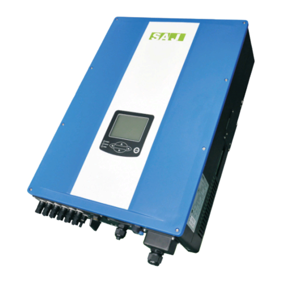
3.Product Overview 3.1 Product Appearance Figure 3.1 Suntrio inverters Overview 3.2 Major Characteristics SAJ Suntrio inverter has following characteristics which make SAJ grid-tied solar inverter “Higher Efficiency, High Reliability and Lower Cost”. Leading technology • Max. efficiency 98.1% • MPPT accuracy up to 99.9% efficiency User-friendly •... -
Page 9: Technical Data
User Manual User Manual 3.3 Technical Data Type Suntrio-TL6K Suntrio-TL8K Suntrio-TL10K Input (DC) Max. DC Power [W] 6300 8200 10400 Max. DC Voltage [V] 1000V MPPT Voltage Range [V] 240~800 240~800 240~800 Nominal DC Voltage Start Voltage[V] Min. DC Voltage[V] Max. - Page 10 User Manual Type Suntrio-TL12K Suntrio-TL15K Suntrio-TL17K Suntrio-TL20K Input (DC) Max. DC Power [W] 12500 15600 17700 20600 Max. DC Voltage [V] 1000V MPPT Voltage Range [V] 240~800 240~800 240~800 240~800 Nominal DC Voltage Start DC Voltage[V] Minimum DC Voltage[V] Max. DC input Current PV1 / PV2 [A] 18/18 22/22 22/22...
-
Page 11: Installation Instructions
Check the delivery for completeness and for any visible external damage. Contact your specialist dealer if anything is damaged or missing. Figure 4.1 Inverter and Accessories Object Quantity Description SAJ Suntrio solar inverter Rear panel 4 sets for Suntrio-TL6K/8K/10K/12K DC connector 6 sets for Suntrio-TL15K/17K/20K M6×50 Expansion screw... -
Page 12: Mounting Instructions
User Manual 4.2 Mounting Instructions Figure 4.2 Mounting Instructions Mounting on a solid surface out door or indoor. ● Site altitude is less than 2,000m above the sea level. ● The mounting location must be clear and safely accessible at all times without the use of additional aids such as scaffolding or lifting platforms. - Page 13 User Manual User Manual Figure 4.3 Safety Clearance of Single Inverter ●Multiple inverters are mounted in an area,the below clearances between the inverters are recommended.This ensure the flow of the air inlet and air outlet openings and optimize heat dissipation. Figure 4.4 Safety Clearance of Multiple Inverters...
-
Page 14: Mounting Procedure
User Manual 4.3 Mounting Procedure 1) Use the rear panel in the package as a drilling template and drill 7 holes with 8mm diameter and depth in 50mm, as illustrated below, (Units: mm) Figure 4.5 Holes Position 2) Fix the rear panel on the wall with the expansion tubes and expansion screw. Figure 4.6 Mounting Real Panel... - Page 15 User Manual User Manual 3) Hang the inverter on the rear panel, and check whether the pothook is installed in place. If there are any errors, remove the inverter, reinstall, as shown below. Figure 4.7 Mounting the Inverter 4) After Confirming the inverter is installed well, tight the inverter with M4 Phillips pan head screws.
-
Page 16: Optional Anti-Theft Protection
User Manual 4.4 Optional Anti-Theft Protection To protect the inverter from theft, you can lock inverter with a padlock. The padlock must meet the following requirements: Size: A:6 mm – 8 mm diameter B:23mm – 29 mm C:23mm – 28 mm D:39mm –... -
Page 17: Electrical Connection
User Manual User Manual 5.Electrical Connection 5.1 Safety NOTICE ●Internal components of the inverter can be damaged by Electrical discharge, take measurement to avoid Electrical discharge during relevant operation. ●Earth yourself before touching any components. 5.2 Overview of Connection Area Figure 5.1 Connection Area Overview of Suntrio-TL6K/8K/10K/12K... - Page 18 User Manual Figure 5.2 Connection Area Overview of Suntrio-TL15K/17K/20K Object Description DC input terminals (PV1 and PV2) DC switch (optional) EXT port Ethernet RJ45 interface AC cover terminal RS485 interface Grounding terminal Table 5.1 Description of Connection Area...
-
Page 19: Connection Cables Requirements
User Manual User Manual 5.3 Connection Cables Requirements The user can select connection cable according the table below. DC Side AC Side Model cross section (cu) Mini cross section (cu) Suntrio-TL6K/8K / 6mm Suntrio-TL10K/12K / 6mm Suntrio-TL15K / 6mm Suntrio-TL17K / 6mm Suntrio-TL20K / 6mm... -
Page 20: Miniature Circuit Breaker
● Never connect several inverters to a single miniature circuit-breaker. In order to securely disconnect the inverter from the PV generate and the public-Grid, SAJ recommend to install circuit breaker at DC Input and AC output as figure 2.1 shown. -
Page 21: Connecting The Electricity Grid (Ac)
User Manual User Manual 5.5 Connecting the Electricity Grid (AC) 5.5.1Conditions for the AC Connection You must comply with the connection requirements of your network operator Residual Current monitoring The inverter is equipped with an integrated all-pole-sensitive residual-current monitoring unit. The inverter can automatically differentiate between residual currents and normal leading leakage currents. - Page 22 User Manual 2)Please insert the striped cable into bootlace ferrule and crimp the contact. 3)Screw off the AC cover and insert the 5 wires into AC cover assembly with the following sequence. 4)Release the five screws at the cable terminal. Then route the 5 wires into the cable terminal according to the marks on the front case while L1(R), L2(S), L3(T) represent 3 Live line, N represent Neutral line and PE is ground.
-
Page 23: Connecting The Second Protective Conductor
User Manual User Manual 5)Screw the cap nut of the cable tightly. 5.5.3 Connecting the Second Protective Conductor If required by the installation, the earth terminal can be used to connect a second protective conductor or as equipotential bonding. Procedure Take out parts from the packing and insert the earthing wire to “PE”... -
Page 24: Connecting The Pv Array (Dc)
User Manual 5.6 Connecting the PV Array (DC) 5.6.1 Conditions for DC Connection NOTE: Suntrio-TL6K/8K/10K/12K: Dual MPPT(PV1 and PV2), two DC input connection sets per MPPT. Suntrio-TL15K/17K/20K: Dual MPPT(PV1 and PV2), three DC input connection sets per MPPT. ● For input area PV1 or PV2, The PV modules must meet the following requirements: Same type Same number of in-series-connected PV modules Identical direction... -
Page 25: Connection Procedures By H4
User Manual User Manual 5.6.2 Connection Procedures by H4: Connect the PV generator and the inverter using H4 connectors, as follows. Note: If using MC4 connector, the operating procedures are similar to that of H4 connector. The DC connectors come pre-assembled and the caps are loose. The whole connector will include the male side and female side as showed below: Male side connector (M) Female side connector (F) - Page 26 User Manual 3)Insert stripped cable into contact barrel and insure all conductor strands are captured in the contact barrel and the conductors are visible in the contact barrel observation hole. Barrel observation hole Conductor should be visible Barrel observation hole Conductor should be visible 4)Crimp contact barrel by using the hex crimping die.
- Page 27 User Manual User Manual 6)Wrest the cap by using the torque of 2.6~2.9N·m. 7)After wrested the cap tightly, align the 2 half connectors and mate them together by hand until a “click” is heard or felt. 8)Connect the positive and negative terminals from the PV panels to positive and negative terminals on the PV inverter.
-
Page 28: Communication And Monitoring Setting
User Manual 5.7 Communication and Monitoring Setting SAJ offers 2 standard communication interfaces for Suntrio-TL series solar inverters: RS485 and Ethernet RJ45. All the SAJ products involved in the solar monitoring system are: SAJ Logger: data logger for local monitoring and maintenance of large solar power plants. - Page 29 1)Inverter 1 connects to Inverter 2 through RS485 cable; Inverter 2 connects to Inverter 3 through RS485 cable. In the same way to connect all inverters. 2)Inverter 1 connects to SAJ Logger through RS485-L cable. 3)Connect SAJ Logger to PC through Router. 4)Open the internal Web Server of SAJ Logger for plant and inverter monitoring.
-
Page 30: Communication Through Ethernet Rj45
All the Wi-Fi bridge or repeater(For example, Edimax EW-7228APn) which has Ethernet RJ45 port can connect to SAJ solar inverters with RJ45 cable and to Wi-Fi router wirelessly.(For details please refer to the document “SAJ Monitoring Solution with Integrated RJ45 Plus Wi-Fi... -
Page 31: Communication Cable Assembly Instructions
User Manual User Manual 5.7.4 Communication Cable Assembly InstructionsAll cables All cables mentioned in this mentioned in this Manual are 5E Shielded Cable, as shown in Figure 5.22. Figure 5.22 5E Shielded Cable Terminals: According to different communication solutions, users may need at least one of the below terminals. - Page 32 User Manual Figure 5.24 RJ45 Plug and Pin Number Tools When making a communication cable, the professional tools shown in Figure 5.25 below are needed. Figure 5.25 Tools for Making a Communication Cable RS485 Cable When using RS485 for monitoring, users need RS485 cables to connect between inverters for multi-point monitoring.
- Page 33 User Manual RS485-L Cable RS485-L cable is used to connect Inverter and SAJ Logger when inverters are monitored via RS485. One end of the cable uses 3Pin Connector, and the other end uses RJ45 Plug. Connection is shown in Table 5.5 as below: Wire Connector No.
-
Page 34: Lcd Operation
User Manual 6. LCD Operation 6.1 LCD Display Overview Figure 6.1 Inverter HMI (Human Machine Interface) Object Description Power status indicator Yellow light on: Inverter power systerm normal Inverter status indicator: Flashing red light: Inverter faulty status. Green light on: Inverter normal status. Red light and Green light are both off: inverter initialization status or inverter counting down to connect to grid. -
Page 35: Startup The Inverter
User Manual User Manual 6.2 Startup the Inverter Suntrio inverter can be configured for various countries, if it is the first time the inverter starts up after installation, LCD will quickly switch to and stay at the country setting interface. Only the inverter is set to comply with a certain country, it will work and display normally. -
Page 36: Lcd Main Screen
User Manual Figure 6.2 Connect to the Gird Countdown 6.3 LCD Main Screen When inverter countdown finishes and starts to connect to grid, LCD will display the main screen as below. The main screen consists of menu bar, main display area, auxiliary display area, status bar (including inverter status, description of main display area, data and time). -
Page 37: Lcd Menu Structure
User Manual User Manual 6.4 LCD Menu Structure Menu structure is shown as Figure 6.4.Menu can be selected by pressing the ‘▲’, ‘▼’, ‘ ’, ‘ ’ and confirmed by pressing ‘Enter’, then LCD main display area will display the information accrodingly. -
Page 38: Lcd Graph Submenu
User Manual 6.4.1 LCD Graph Submenu Graph submenu consists of E-Today, E-Month, E-Year and E-Total. LCD main display area will display the corresponding information after confirming the Graph submenu by pressing ‘Enter’. The Figure 6.5 below is the E-Month Screen.please refer to the Table 6.4 for E-Today, E-Month, E-Year and E-Total display information explanation. -
Page 39: Lcd Setting Submenu
User Manual User Manual 6.4.2 LCD Setting Submenu Setting submenu includes the below setting of the inverter: Ethernet: Figure 6.6 is the Ethernet setting screen.Either the IP address is set to be obtained auto or manually, the IP address displayed on the screen is the current IP address of the inverter. The focus can be moved by pressing the ‘... - Page 40 User Manual Figure 6.7 Inverter Embedded Web Server Screen Language & Time: Move the focus to the setting item by using ‘ ’, ‘ ’ , and the setting can be changed by pressing ‘▲’, ‘▼’. The setting will be saved by moving the focus to ‘OK’ and press ‘Enter’. Figure 6.8 Language &...
- Page 41 User Manual User Manual Grid Compliance:(only for SAJ or SAJ representative) Different country has different grid connection standard for inverter. The grid compliance of the inverter can be changed by this setting menu when the inverter is run for the first time or the country selection is wrong.
- Page 42 User Manual Figure 6.10 Clear Energy Operation Screen. LCD Setting: LCD setting includes: LCD backlight brightness and LCD backlight Time-out, as shown in Figure 6.11.Press ‘ ’, ‘ ’to move the focus and press ‘▲’, ‘▼’ to change the value. After the change, move the focus to button ‘OK’...
- Page 43 Figure 6.12 Factory Reset Screen Change Password (only for SAJ or SAJ representative) SAJ or SAJ representative can change the passwords for ‘Grid Compliance’ and ‘Factory Setting’. After entering this menu, the old password will be required. After passing the old password verification, the screen will be displayed as below, as shown in Figure 6.13.
- Page 44 User Manual ■Run-Info AC-Parameters: Inverter AC output data can be viewed in the menu, as shown in Figure 6.14 . Figure 6.14 AC Parameters Screen DC-Parameters: DC data can be viewed in this screen, as shown in Figure 6.15. Figure 6.15 DC Parameters interface...
- Page 45 User Manual User Manual Error-Records: Inverter error record can be viewed in this menu, as shown in Figure 6.16. The screen can be scrolled by pressing ‘▲’, ‘▼’. Error record can be flipped over to another one by moving the cursor to button ‘Previous’...
-
Page 46: Error Report Mechanism And Guidance
(Control Board Master MCU Software Version) Slave Ctrl. SW (Control Board Slave MCU Software Version) Portal ID. The Portal account ID for Web portal registration: http://webportal.saj-solar. com. The inverter has to be connected to internet, otherwise it will keep displaying Portal ID ‘Getting…’, If the inverter is connected to the internet, but it still keeps displaying... -
Page 47: Recycling And Disposal
User Manual User Manual 7.Recycling and Disposal To comply with European Directive 2002/96/EC on waste Electrical and Electronic Equipment and its implementation as national law, electrical equipment that has reached the end of its life must be collected separately and returned to an approved recycling facility. Any inverter that you no longer required must be returned to your dealer or you must find an approved collection and recycling facility in your area. -
Page 48: Troubleshooting
Belgium, Netherlands, etc) and 2)The connection between Grid and L2 Voltage Low M Grid voltage. If everything is inverter has problems. correct, you need to contact L3 Voltage High M local agent or SAJ Service line. L3 Voltage Low M... - Page 49 If everything is inverter has problem. correct, you need to contact L3 Freq High M local agent or SAJ Service line. L3 Freq Low M L1 No Grid Err M Check the AC connection. If The connection between Grid and...
- Page 50 BUS voltage. If the error is still active, please Bus Volt Bal.Err M 2)If random, a possible cause is the contact the local agent or SAJ Service line. quick variation of grid voltage. 1)The open-circuit voltage of the PV...
- Page 51 Phenomenon and Possible Cause Message Possible Cause Reserved(bit 52) M Communication between Master Please contact local agent or SAJ Lost Com. M<->S S and Slave Micro-controllers fails. Service line. L1 Volt Consis Err S If the error is still active, please...
- Page 52 SAJ Service line. L3 No Grid Err S C h e c k t h e P V s t r i n g...
-
Page 53: Guaranty Service
User Manual 9.Guaranty Service Please refer to the warranty card. 10.Contact SAJ If you have technical problems concerning our products, contact the SAJ Service line. Technical Support & Service: International Service & Technical Support Addr: No.17, Xiangshan Road Guangzhou Science City,Guangdong,R.China.
Need help?
Do you have a question about the Suntrio-TL Series and is the answer not in the manual?
Questions and answers