Printronix T5000 User Manual
Hide thumbs
Also See for T5000:
- Software manual (298 pages) ,
- Programmer's reference manual (88 pages) ,
- Quick setup manual (74 pages)
Table of Contents
Advertisement
Advertisement
Table of Contents

Related Manuals for Printronix T5000


Summary of Contents for Printronix T5000
- Page 1 User’s Manual T5000 Thermal Printer...
-
Page 3: Software License Agreement
The term "Software Product" includes the Software resident in the printer and its documentation. The Software Product is licensed (not sold) to you, and Printronix, Inc. either owns or licenses from other vendors who own, all copyright, trade secret, patent and other proprietary rights in the Software Product. -
Page 4: Limited Software Product Warranty
LIABILITY FOR CONSEQUENTIAL OR INCIDENTAL DAMAGES, SO THE ABOVE LIMITATION MAY NOT APPLY TO YOU. 3. Printronix, Inc. will not be liable for any loss or damage caused by delay in furnishing a Software Product or any other performance under this Agreement. -
Page 5: Communication Notices
Termination of License Agreement This License shall continue until terminated. This license may be terminated by agreement between you and Printronix, Inc. or by Printronix, Inc. If you fail to comply with the terms of this License and such failure is not corrected within thirty (30) days after notice. - Page 6 This product is in conformity with the protection requirements of EC Council Directive 89/336/EEC on the approximation of the laws of the Member States relating to electromagnetic compatibility. Printronix cannot accept responsibility for any failure to satisfy the protection requirements resulting from a non-recommended modification of the product, including the fitting of non-Printronix option cards.
- Page 7 Warning This is a Class A product. In a domestic environment this product may cause radio interference in which case the user may be required to take adequate measures.
-
Page 8: Trademark Acknowledgements
Trademark Acknowledgements Printronix, IGP, IGP/Auto Label Mapping, LinePrinter Plus, PGL, and PrintNet are registered trademarks of Printronix, Inc. ThermaLine is a trademark of Printronix. HP is a registered trademark of Hewlett-Packard Company. PCL is a registered trademark of Hewlett-Packard Company. -
Page 9: Important Warranty Information
IMPORTANT WARRANTY INFORMATION PRINTER WARRANTY Printronix ® warrants to purchaser that under normal use and service, this printer (excluding the thermal printhead) purchased hereunder shall be free from defects in material and workmanship for a period of ninety (90) days from the date of shipment from Printronix. -
Page 11: Table Of Contents
Table of Contents 1 Introduction............17 Printronix Customer Solutions Center ..........17 Training Available On Printronix Products ........... 17 Warnings And Special Information ............18 Manual Conventions ................18 The T5000 Series Label Printer............19 Standard Features ................ 19 Optional Features................20 Thermal Printer Technology .............. - Page 12 Table of Contents Printing Adjustments................59 Printhead Pressure Adjustment ............ 59 Printhead Pressure Block Adjustments ......... 60 Positioning The Media Sensor ............61 Sensing Different Media Types ............. 62 Running Auto Calibrate ..............63 Running Media Profile..............64 Running Manual Calibrate............. 66 Cleaning....................
- Page 13 Table of Contents IGP/PGL SETUP ................140 IGP/VGL SETUP ................142 P-SERIES SETUP ................145 P-SER XQ SETUP................148 SER MATRIX SETUP................ 150 PROPRINTER SETUP ..............152 EPSON FX SETUP................154 Emulation Submenus................. 156 DIAGNOSTICS .................. 200 DIAGNOSTICS Submenus ............201 PARALLEL PORT................
- Page 14 Acoustic Specifications ............... 274 B Printer Options ..........275 Hardware Options................275 Interface Options ................. 276 Supplies And Accessories ..............277 Genuine Printronix Thermal Transfer Ribbons......277 Genuine Printronix Media............278 Accessories ................. 280 C ASCII Control Codes ........281...
- Page 15 Table of Contents D Standard And Heavy-Duty Media Cutter Installation ............283 Prepare The Printer ................283 Installing The Standard Cutter ............ 284 Restore The Printer To Operation ..........284 Installing The Heavy-Duty Cutter ..........286 Restore The Printer To Operation ..........286 Removing The Media Cutter..............
- Page 16 Table of Contents...
-
Page 17: Introduction
Theory of operation • Diagnosis of equipment failures • Preventive and corrective maintenance requirements and procedures. Customized classes designed to meet your specific needs are available upon request. Call Customer Training at (714) 368-2332 or visit the Printronix Web page at www.printronix.com. -
Page 18: Warnings And Special Information
Chapter Warnings And Special Information Warnings And Special Information For your safety and to protect valuable equipment, it is very important that you read and comply with all information highlighted under special headings: WARNING Conditions that could harm you and damage the equipment. WARNING Achten Sie auf folgendes, um keine Personen in Gefahr zu bringen bzw. -
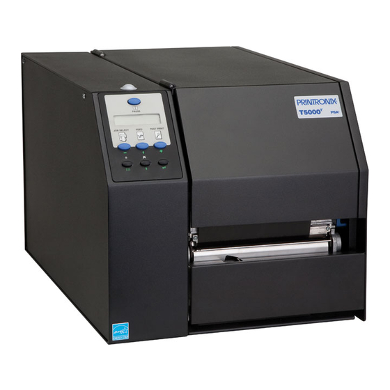
Page 19: The T5000 Series Label Printer
Standard Features The T5000 Series Label Printer NOTE: As used in this manual, the terms “T5000” and “printer” refer to all models within the T5000 series. The T5000 series consists of a family of high quality, direct thermal and thermal transfer printers specifically designed for printing labels and tags from ®... -
Page 20: Optional Features
8MB DRAM memory. • 4MB Flash memory. ® • Auto Label Mapping for compatibility with programs written for Printronix Line Matrix printers. Optional Features Ask your authorized representative about the following options which can enhance the versatility of your printer: •... - Page 21 Printronix offers an integrated online validation system as an option for the T5000 printer. Other validation tools, such as hand-held models, may be obtained from the RJS company. RJS designs and manufactures the world’s most complete line of bar code validation products, including their portable Inspector and Laser Inspector models, On-Line Inspector and AutoScan II series.
-
Page 22: Thermal Printer Technology
Chapter Thermal Printer Technology Thermal Printer Technology Quiet and fast, with excellent print quality, your multifunction thermal printer uses an inline thermal printhead. The thermal printer operates differently from a line matrix or laser printer, because the thermal printer uses a printhead with heating elements and special paper or ribbon. -
Page 23: Thermal Consumables
Most of these media options can be die-cut for easy label applications. The wide selection of media sizes and face stocks have been tested with Printronix ribbons for print quality and usage. Consult your Genuine Printronix Supplies Catalog or contact the factory. -
Page 24: Setting Up The Printer
Chapter Setting Up The Printer Setting Up The Printer Unpacking The Printer The printer is shipped in a carton and protective bag. The top lid of the carton has instructions on how to remove the internal packing material from the printer. - Page 25 Unpacking The Printer Foam 4. Remove the foam pad between the pivoting deck and the frame. Pivoting Deck Platen Foam Deck Lock Lever Printhead 5. Open the pivoting deck by rotating the blue deck lock lever fully clockwise. 6. Remove the foam pad from between the printhead and the platen (rubber roller).
-
Page 26: Installation
Chapter Setting Up The Printer Installation The following sections will guide you through the installation of the printer. 1. Place the printer in a suitable location on a flat level surface that allows easy access to all sides of the printer. CAUTION The printer should never be operated while resting on its side or upside down. - Page 27 Installation 5. Attach Interface: a. Parallel Interface Attach a suitable parallel printer cable from the computer to the Centronics/IEEE 1284 interface connector at the back of the printer. Snap the bail locks to the Centronics connector to secure the interface cable to the printer. b.
- Page 28 Chapter Setting Up The Printer If your printer is equipped with the Coax/Twinax and Network Interface Card (NIC) interfaces, the rear I/O panel will look like the picture below. Twinax Connection Coax Connection NIC Connection c. Coax Connection Attach a suitable coaxial cable from the computer to the coax connector located in the I/O plate in the back of the printer.
-
Page 29: Operation
Operation Controls And Indicators Power Switch The power switch is located on the bottom back panel of the printer. To apply power, place the switch in the | (ON) position. When you first power on the printer, a series of initialization messages will appear on the control panel Liquid Crystal Display (LCD). - Page 30 Function in Function in Function in Indicator Description Online Mode Offline Mode Menu Mode Online Status Indicates when the Stays lit when the Off when the printer is Off. printer is online, offline, printer is online, ready offline. or when there is a fault to print, and accept condition.
- Page 31 Function in Function in Function in Button Description Online Mode Offline Mode Menu Mode PAUSE Key Sets printer to Offline Sets printer to Online Sets printer to Offline Toggles the printer between Mode. Mode. Mode. online and offline modes. JOB SELECT Key None Selects a pre-stored Scrolls left through...
- Page 32 Function in Function in Function in Button Description Online Mode Offline Mode Menu Mode CANCEL Key None Clears all data in the Scrolls the current When the CANCEL key is enabled, printer data buffer menu selection one pressing it will clear all data in the when enabled.
-
Page 33: Powering On The Printer
Powering On The Printer Powering On The Printer When you power on the printer, it executes a self-test. During the self-test, the LCD momentarily displays the DPI resolution (203 or 300 DPI) of the installed printhead. The default power-on state is online. Once the printer has successfully initialized, the ONLINE status indicator light illuminates, and the LCD indicates the communication interface selected and the type of emulation installed. -
Page 34: Loading Media And Ribbon
Chapter Loading Media And Ribbon • Peel-Off. Prints and peels die-cut labels from the liner without assistance. The printer waits for you to take away the label before printing the next one (on-demand printing). The label liner is rewound on the optional internal rewinder. -
Page 35: Loading Roll Media
Loading Roll Media Loading Roll Media Media Cover Media Hanger Media Hanger Guide Pivoting Deck Media Width Guide Deck Lock Lever 1. Open the media cover. 2. Slide the blue media hanger guide outward to the end of the media hanger, and flip it down horizontally. - Page 36 Chapter Loading Media And Ribbon Media Roll Media Hanger Guide Media Hanger 5. Slide a roll of media onto and towards the back of the media hanger. The media feeds from the top of the roll and towards the front of the printer. 6.
- Page 37 Loading Roll Media Printhead Media Damper Platen (Rubber Drive Roller) 7. Thread the media under the media damper and then between the platen (rubber drive roller) and the printhead. You can also refer to the arrows on the printer frame or to the label inside the media cover for media loading instructions.
- Page 38 Chapter Loading Media And Ribbon Media Sensor Media Guard Fixed Guide Media Width Guide Media Damper Media Sensor Handle 8. Verify that the left (inside) edge of the media is against the fixed guide on the bottom of the media damper. 9.
- Page 39 Loading Roll Media Media Platen (left edge) (left edge) 11. Align the left (inside) edge of the media with the left straight edge of the platen (rubber drive roller).
- Page 40 Chapter Loading Media And Ribbon Pivoting Deck Deck Lock Lever 12. Close the printhead by pressing down on both sides of the pivoting deck and rotating the deck lock lever fully counterclockwise. IMPORTANT Ensure the pivoting deck is down and locked before attempting to advance media or print.
-
Page 41: Loading Fanfold Media
Loading Fanfold Media Loading Fanfold Media Media Cover Fanfold Tension Fanfold Media Pivoting Deck Media Hanger Guide Media Hanger Deck Lock Lever 1. Open the media cover. 2. Slide the media hanger guide outward to the end of the media hanger, and rotate it downward to a horizontal position to remove any roll media. - Page 42 Chapter Loading Media And Ribbon Media Sensor Media Guard Fixed Guide Media Width Guide Media Damper Media Sensor Handle 8. Slide the media width guide outward to the end of the media damper. 9. Thread the media under the media damper and then between the platen (rubber drive roller) and the printhead.
- Page 43 Loading Fanfold Media Media Platen (left edge) (left edge) 12. Align the left (inside) edge of the media with the left straight edge of the platen (rubber drive roller).
- Page 44 Chapter Loading Media And Ribbon Pivoting Deck Deck Lock Lever 13. Close the printhead by pressing down on both sides of the pivoting deck and rotating the deck lock lever fully counterclockwise. This locks the pivoting deck and printhead assembly into the printing position. Verify that Print Mode in the Printer Configuration Menu is set for the media type installed (Direct or Transfer).
-
Page 45: Loading Ribbon
Loading Ribbon Loading Ribbon Skip this section for 4 inch DT models or when using direct thermal printing. Pivoting Deck Ribbon Roll Ribbon Supply Spindle Deck Lock Lever 1. Install the empty supply core on the take-up spindle. 2. Slide the ribbon roll onto the ribbon supply spindle until it stops against the spindle flange. - Page 46 Chapter Loading Media And Ribbon Printhead Media Rear Ribbon Guide Roller 4. Thread the end of the ribbon under the rear ribbon guide roller, then between the platen and the printhead. You can also refer to the arrows on the printer frame or to the label inside the media cover for media loading instructions.
- Page 47 Loading Ribbon Media Cover Take-up Core Take-up Spindle 5. Wrap the ribbon from the front of the printhead assembly to the front of the ribbon take-up spindle. Attach the ribbon to the fiberboard core on the ribbon take-up spindle with tape. When installing a new roll of ribbon, attach the ribbon leader adhesive strip to the ribbon take-up core.
-
Page 48: Removing The Media Guide
Chapter Loading Media And Ribbon 8. Verify that Print Mode is set for Transfer in the Print Mode submenu located in the MEDIA CONTROL Main Configuration menu. See “Main Menu” on page 79 for more information. 9. The printer is now ready to print. Removing The Media Guide Remove the media guide from the front door when using Tear-Off or Tear-Off Strip media handling, because you will need to tear the label downward... -
Page 49: Using The Optional Internal Rewinder
Batch Rewind Mode Using The Optional Internal Rewinder The printer can be set up to rewind labels after they have been printed (Batch Rewind Mode) or to automatically peel labels from their backing and dispense them one at a time while rewinding the liner (Peel-Off Mode). Both modes require use of an internal rewinder. -
Page 50: Installing The Media Guide
Chapter Using The Optional Internal Rewinder Installing The Media Guide The media guide must be installed on the front door when using Batch Rewind mode. To install the media guide: Front Door Media Guide Hook Groove 1. Open the front door by pulling it upwards, then forward. 2. -
Page 51: Loading Media
Batch Rewind Mode Loading Media Rewinder Release Lever Rewinder 1. To load media, refer to “Loading Roll Media” on page 35 and complete steps 1 through 10. - Page 52 Chapter Using The Optional Internal Rewinder Media Media Guide Release Slot Lever 2. Thread the media over the front of the media guide and through the opening under the front door toward the internal rewinder. IMPORTANT If you do not complete the following step, it will be extremely difficult to remove the printed labels from the rewinder.
- Page 53 Batch Rewind Mode Media Cover Deck Lock Lever 6. Press down on both sides of the pivoting deck and rotate the deck lock lever counterclockwise against its stop to place the printhead assembly into the printing position. 7. Press the FEED key to advance the media to the next TOF (Top-of-Form) position.
- Page 54 Chapter Using The Optional Internal Rewinder Removing Printed Media from the Rewinder Release Lever Printhead Rewinder 1. Open the media cover. 2. Press the FEED key to advance the last printed label past the printhead, and tear the liner from behind the last printed label. 3.
-
Page 55: Label Peel-Off
Label Peel-Off Label Peel-Off You can set up the printer to automatically peel die-cut labels off their liner (backing) and dispense them one at a time while rewinding the liner. You can install the media guide to prevent long labels from accidentally adhering to the front door assembly, but it is normally not needed when using labels less than two inches long (see “Installing The Media Guide”... - Page 56 Chapter Using The Optional Internal Rewinder Raised Ridge Back Flange Slot Release Lever Liner IMPORTANT If you do not complete the following step, it will be difficult to remove the liner from the rewinder. 6. Turn the release lever on the rewinder counterclockwise and lock it in place.
- Page 57 Label Peel-Off Media Cover Deck Lock Lever 12. Press down on both sides of the pivoting deck and rotate the deck lock lever fully counterclockwise. 13. Press the FEED key. The label advances to the peel-off position, and “Remove Label” displays on the LCD. 14.
-
Page 58: Removing Label Liner From The Rewinder
Chapter Using The Optional Internal Rewinder Removing Label Liner from the Rewinder 1. Open the media cover. 2. Open the front door. 3. Tear the liner at the tear bar. 4. Manually rewind the remaining liner onto the rewinder by turning the rewinder counterclockwise. -
Page 59: Printing Adjustments
Printhead Pressure Adjustment Printing Adjustments Printhead Pressure Adjustment Active Pressure Setting Printhead Pressure Adjustment Dial Sometimes you will need to adjust printhead pressure because of variations in media thickness and width. The printhead pressure adjustment dial is shown above. The value shown at the bottom of the dial is the active setting. In general, adjust printhead pressure to the lowest value which produces the desired print quality. -
Page 60: Printhead Pressure Block Adjustments
Chapter Printing Adjustments Printhead Pressure Block Adjustments Pressure Block Adjustment Scale Right Pressure Block Pointer Lead Screw Left Knob Pressure Block Left Pressure Block Handle Right Pressure Block Printhead Pressure Block adjustments are used to obtain a uniform print density across the width of the installed media under a variety of media and ribbon conditions. -
Page 61: Positioning The Media Sensor
Positioning The Media Sensor 3. Press the ↵ key to start the Grey test pattern. The pattern will start and continue to print. 4. Press the ↵ key to stop printing. 5. Check the test pattern. If necessary reposition the pressure blocks to obtain a uniform print density across the media width. -
Page 62: Sensing Different Media Types
Chapter Printing Adjustments NOTE: The media sensor should not be placed in the path of media features that could cause false gap detection or paper out faults. Such features are dark pre-printing, rounded die-cut label corners, vertical gaps associated with side-by-side labels, and extraneous cut-outs, as shown below. -
Page 63: Calibrating The Media Sensor
Running Auto Calibrate ↵ 6. Press the key to enable the displayed option. An asterisk (*) appears next to the selection. 7. Press the PAUSE key until “OFFLINE” appears on the LCD. 8. Review the Calibrating the Media Sensor section below. 9. -
Page 64: Running Media Profile
Chapter Printing Adjustments 2. Press the ↓ key and ↵ key together until “ENTER SWITCH UNLOCKED” displays. 3. Press the TEST PRINT key until “Printer Tests/Auto Calibrate” displays. ↵ 4. Press the key. Media advances until it can accurately detect the label length indicators and then stops at the Top-of-Form position. - Page 65 Running Media Profile NOTE: Verify that the CALIBRATE CTRL menu Gap/Mark Sensor option (Gap, Mark or Disable) matches the installed media. See “Sensing Different Media Types” on page 62. You will need a minimum installed label width of two inches to support the Profile printout.
-
Page 66: Running Manual Calibrate
Chapter Printing Adjustments Running Manual Calibrate Manual Calibrate should be performed only when the values derived from Auto Calibrate fail to improve the media sensor’s ability to sense label length indicators on the installed media. You must first enable Advanced User in the PRINTER CONTROL menu before accessing or initializing Manual Calibrate in the CALIBRATE CTRL menu. -
Page 67: Cleaning
General Cleaning 11. Press the FEED key several times. Each time the FEED key is pressed the media should advance one label length and stop. NOTE: After a form feed, the position of the leading edge of the next label depends on the type of Media Handling Mode selected under the MEDIA CONTROL menu. - Page 68 Chapter Cleaning Pivoting Deck Printhead Elements Deck Lock Lever 1. Rotate the deck lock clockwise to open the pivoting deck and remove any media and ribbon (if loaded) to gain access to the printhead assembly heating element area. 2. Gently rub the felt tip of the Cleaning Pen or a cotton swab with Isopropyl alcohol across the printhead heating elements (light brown area).
-
Page 69: Configuring The Printer
Configuring The Printer Overview The configuration process is done using the printer configuration keys on the control panel and includes the following: • Configuring the printer for different host interface options • Customizing label formats • Checking printer status • Running various maintenance tests NOTE: Control codes sent by the host system will override the control panel settings. -
Page 70: Moving Within The Configuration Menu
Chapter Overview Moving Within The Configuration Menu You can move through the configuration menus using the appropriate navigation keys, as shown in Figure 2. (See “Controls And Indicators” on page 29 for more details on the function of the operator panel keys.) You can select different options and save them as the power on default;... -
Page 71: Selecting A Menu Option
Selecting A Menu Option Selecting A Menu Option To select an option, you need to press the ↵ key. By default, however, the ↵ key is “locked” when the printer is turned on to prevent accidental changes to the configuration menu. If you press the ↵ key when the key is locked, the message “ENTER SWITCH LOCKED”... -
Page 72: Saving A Configuration
Chapter Overview • Ver Image Shift • Hor Image Shift • Orientation 3. When the desired submenu displays, press the or - key to scroll through the values or options. 4. Press the ↵ key to select a value. An asterisk (*) displays next to the selected value or option. -
Page 73: Specifying A Power-Up Configuration
Specifying A Power-Up Configuration When processing is completed, the display shows: Save Config. NOTE: If the configuration number has been previously saved and Protect Configs. = Enabled under CONFIG CONTROL, the following error message displays: CONFIG. EXISTS Delete First If the above occurs, see “Modifying A Saved Configuration” on page 74, step 4. -
Page 74: Modifying A Saved Configuration
Chapter Overview Modifying A Saved Configuration You can change a saved configuration by rewriting over it. For example, you can modify Config. 1, shown below. Suppose you want to keep all the settings but you want to select the parallel Centronics interface instead of the IEEE 1284 interface. -
Page 75: Printing A Configuration
Printing A Configuration Then, the following displays when it is deleted: Delete Config. 5. Save the new configuration as described in the “Saving A Configuration” on page 72. Make sure you select the same number (e.g., Config. 1) when saving the modified configuration. The new configuration writes over the existing one. - Page 76 Chapter Overview Figure 3. Sample Configuration Printout...
- Page 77 Sample Configuration Printout (cont.)
-
Page 78: Menu Overview
Chapter Menu Overview Menu Overview VALIDATOR CONFIG. MEDIA CALIBRATE PRINTER CONTROL CONTROL CONTROL CONTROL Online validator Name, store, and Control various Select the correct Select the setup and status retrieve up to parameters media sensing desired reporting. eight different related to print for the media emulations and printer... -
Page 79: Main Menu
Main Menu VALIDATOR CONFIG. MEDIA CALIBRATE CONTROL CONTROL CONTROL (page 84) (page 91) (page 94) (page 108) Validator Report Load Config. Print Intensity Gap/Mark Sensor Auto Report Save Config. Print Speed Auto Calibrate Clear Data Print Config. Print Mode Media Profile Good Barcodes Delete Config. - Page 80 Chapter Main Menu TWINAX SPC COAX PRINTER COAX (1)(2)(3) (1)(2)(5) (1)(2)(3) SETUP SETUP CONTROL SETUP (page 131) (page 134) (page 114) (page 128) LP+ Emulation Primary Sets Primary Sets SPC Type CTHI Emulation Translation Tbl Translation Tbl Logical Buf Size Active IGP Emul Buffer Print Intervention Req...
- Page 81 5250 SETUP IGP/PGL IGP/VGL P-SERIES (page 138) SETUP SETUP SETUP (page 140) (page 142) (page 145) Primary Sets Character Group SFCC Select CPI Translation Tbl Standard Sets Power-up ^X Select LPI Buffer Print Select LPI Power-up ^F Typeface Active Char Set Define CR Code Power-up ^PY Character Group...
- Page 82 Chapter Main Menu P-SER XQ SER MATRIX PROPRINTER EPSON FX SETUP SETUP SETUP SETUP (page 148) (page 150) (page 152) (page 154) Select CPI Select CPI Select CPI Select CPI Select LPI Select LPI Select LPI Select LPI Typeface Typeface Typeface Typeface Horizontal DPI...
- Page 83 DIAGNOSTICS PARALLEL SERIAL C/T PORT PORT PORT (page 200) (page 204) (page 208) (page 216) Printer Tests Port Type Port Type Port Type Test Count Data Bit 8 Baud Rate Device Address Software Build PI Ignored Word Length Image Buf Size Hex Dump Mode Buffer Size in K Stop Bits...
-
Page 84: Validator
Chapter VALIDATOR VALIDATOR VALIDATOR Validator Report Auto Report Disable* Enable Clear Data Good Barcodes Good Forms Overstrike Forms Average BWD Last BWD Validator Funct. Disable* Enable Telemetry Path Disabled* Serial Port Network Port Telemetry Data Short Report* Full Report Validation Mode Number of Codes Auto* 1-99... - Page 85 VALIDATOR (cont. from previous page) Min. Code Height 0.40 inches* 0.13 inches 0.16 inches 0.20 inches 0.25 inches 0.32 inches Form Spacing 0.6 inches* 0.2 to 1.7 inches Minimum* Maximum Skip Labels F/W Revision Overstrike Style Grid* Grey Checkerboard Scanner Settings 4xx, 6yy, 8zz* Beam Shift -99 to 99...
-
Page 86: Validator Submenus
Chapter VALIDATOR VALIDATOR Submenus Validator Report This item invokes an action. When selected the printer will print a report of the verification data acquired since the last data reset. Auto Report This option allows you to disable or enable an automatic validator report printout after a batch job. -
Page 87: Last Bwd
VALIDATOR Submenus Last BWD This is a display item only. It indicates the Bar Width Deviation included in the most recent report received from the validator. If no data has been received since the last clear operation, this field will be zero. Validator Funct. -
Page 88: Validator Action
Chapter VALIDATOR Validator Action This submenu defines the action the printer will take in the event of an error. See the Validator User’s Manual for details. The options are Retry Form (the factory default), Stop, and Overstrike. Symbol Contrast This item selects whether or not symbol contrast is included as part of the pass fail criteria. -
Page 89: Min. Code Height
VALIDATOR Submenus Min. Code Height This submenu tells the printer the closest vertical gap between bar codes that needs to be resolved. Refer to the Print/Slew Speed Limits for background information. The printer’s ability to resolve which form contains the bad bar code, is a function of print speed and the closeness of bar codes on separate forms. -
Page 90: Beam Shift
Chapter VALIDATOR Beam Shift This option enables you to shift the beam horizontally to the left or right. The left edge of the beam should be 0.13 inch to the left of the left edge of the tear bar. After you set this value, save it as part of the configuration for future use. The range is from -99 to 99, and the factory default is 0. -
Page 91: Config. Control
VALIDATOR Submenus CONFIG. CONTROL CONFIG. CONTROL Load Config. Factory* Save Config. Print Config. Current* Factory Power-Up Delete Config. Power-Up Config. Factory* Protect Configs. Disable* Enable Name Config 1 Name Config 2 Name Config 3 Name Config 4 Name Config 5 Name Config 6 Name Config 7 Name Config 8... -
Page 92: Config. Control Submenus
Chapter CONFIG. CONTROL CONFIG. CONTROL Submenus Load Config. The printer can store up to eight configurations in memory. This parameter allows you to select and load a specific configuration. The factory default is Factory. Save Config. This option allows you to save up to eight unique configurations to meet different print job requirements. -
Page 93: Name Config
CONFIG. CONTROL Submenus Name Config (1-8) You may specify a 15 character name which can be used to refer to a configuration. The name you enter for a configuration will be used in the Load Config., Save Config., Print Config., Delete Config., and Power-Up Config. menus. -
Page 94: Media Control
Chapter MEDIA CONTROL MEDIA CONTROL MEDIA CONTROL Print Intensity -15 to 15 Print Speed 6 ips* 2-10 ips Print Mode Transfer* Direct Media Handling Continuous* Tear-Off Strip Tear-Off Peel-Off Paper Feed Shift 0.00 inches* -0.50 to X inches Label Length (2)(3) 4 or 6 inches* 00.1 to 99.0 inches... - Page 95 CONFIG. CONTROL Submenus MEDIA CONTROL (cont. from previous page) Pre-Peel Mode Disable* Enable Pre-Peel Adjust 1.00 inches* 0.00 to 2.00 inches Clip Page Enable* Disable Error Recover Disable* Enable Ribbon Width Same as Paper* Set in Menu Display Ribbon Enable* Disable Ribbon Low Disable*...
-
Page 96: Media Control Submenus
Chapter MEDIA CONTROL MEDIA CONTROL Submenus Print Intensity This option specifies the level of thermal energy from the printhead to be used for the type of media and ribbon installed. Large numbers imply more heat (thermal energy) to be applied for each dot. This has a significant effect on print quality. -
Page 97: Paper Feed Shift
MEDIA CONTROL Submenus • Peel-Off. Prints and peels die-cut labels from the liner without assistance. The printer waits for you to take away the label before printing the next one (on-demand printing). The label liner is rewound on the internal rewinder. -
Page 98: Label Width
Chapter MEDIA CONTROL • Logical Label Length (Host Forms Length) is the length that the user or programmer bases his printable image on. In most cases this length should be slightly less than the Physical Label Length. This allows the entire image to be printed within the boundaries of the label length indicators (gaps, notches, holes or black marks). -
Page 99: Ver Image Shift
MEDIA CONTROL Submenus Ver Image Shift This option specifies the amount to shift an image vertically up (-) or down (+) for precise positioning on the label. The actual height of the image is not affected by this parameter. The allowable range is -1.00 inches to the current Label Length value setting up to a maximum of 12.80 inches in .01 inch increments. - Page 100 Chapter MEDIA CONTROL • Inv. Portrait. Inverse Portrait refers to vertical page orientation, where the height of a page is greater than its width. The top edge of the image is parallel to the trailing edge of the media. The following illustration is an example, with the operator viewing the front of the printer.
-
Page 101: Auto Map Select
The IGP/Auto Label Mapping feature allows backward compatibility of programs written for P5000 line-matrix printers using the Printronix PGL graphics language. It allows the printer to print two-up (or other multi-up) labels. Instead of printing multiple labels across the printer, it prints the leftmost label and the rightmost label, so the printout will be twice as long but half as wide. - Page 102 Chapter MEDIA CONTROL Example 2: Uneven Number Case Problem: A file has been constructed with three horizontally adjacent 2” labels. The user now desires to use this file with a printer that has a 4” physical width. Solution #1: The user sets Auto Label Width to 4” (the width of two labels), configures the Num Auto Labels to 2, and enables the Auto Label Mapping feature.
-
Page 103: Auto Label Width
MEDIA CONTROL Submenus Example 3: Past Maximum File Width Problem: A file has been constructed with three horizontally adjacent 4” labels. The user now desires to use this file with a printer that has a 8” physical width. The user should have used a solution similar to one of the solutions in the section above, but the user erroneously enters an Auto Label Width of 12”... -
Page 104: Num Auto Labels
Chapter MEDIA CONTROL Num Auto Labels The desired number of labels to be printed vertically adjacent on the form. The value is selectable with a range of 1 through 40 (T5X04), 1 through 21 (T5X06) and 1 through 17 (T5X08). The factory default is 2. -
Page 105: Tear-Strip Time
MEDIA CONTROL Submenus Table 3. Head First Print Direction Result in Active IGP Emulations Orientation Option Option (IGP/PGL or IGP/VGL) Head First Inv. Portrait Inv. Portrait Head First Inv. Landscape Inv. Landscape Table 4. Foot First Print Direction Result in Active IGP/PPI1 Orientation Option Option Emulation... - Page 106 Chapter MEDIA CONTROL Clip Page This option determines how the printer handles images that are too large for one physical page length when using gap or black mark media. • Enable. When the user selected page length is greater than the physical page length, the printer clips the excess data to fit the physical page.
-
Page 107: Ribbon Low
MEDIA CONTROL Submenus Ribbon Low This menu item defines the Ribbon Low condition for the ribbon supply spindle. When set to a specific value from the available ranges (25, 50, 75, 100m), a ribbon low message will be displayed along with a flashing ONLINE status indicator when the length of ribbon remaining on the ribbon supply spindle has reached that value. -
Page 108: Calibrate Ctrl
Chapter CALIBRATE CTRL CALIBRATE CTRL CALIBRATE CTRL Gap/Mark Sensor Mark Disable Auto Calibrate Run Calibrate Media Profile Print Profile Sensed Distance 0.00 inches Gap/Mark Thresh 171* 000-255 Paper Out Thresh 250* 000-255 Manual Calibrate Run Calibrate Pwr Up Auto-Cal Disable* Enable Online Auto-Cal Disable*... -
Page 109: Calibrate Ctrl Submenus
CALIBRATE CTRL Submenus CALIBRATE CTRL Submenus Gap/Mark Sensor The available options specify the sensor type needed for detecting the Top-of- Form position on media with label length indicators (gaps, notches, holes or black marks). • Disable: Selected when using media with no label length indicators (no gaps, notches, holes or black marks), or when you want the printer to ignore all existing label length indicators on the installed media. -
Page 110: Media Profile
Chapter CALIBRATE CTRL Media Profile This feature provides a graphical printout showing the relationship of the Paper Out Threshold and the Gap/Mark Threshold. The profile printout assists the user in setting the thresholds for difficult media. This includes pre- printed labels, and labels with poor gap/media dynamic range. When selected, the printer will advance media and print the media profile along the length of each label. -
Page 111: Manual Calibrate
CALIBRATE CTRL Submenus Manual Calibrate Manual Calibrate is another method of improving the printer’s Media Sensing and is only used when Auto Calibrate has failed or the Gap/Mark Threshold or Paper Out Threshold values derived from Auto Calibrate do not improve the media sensor’s gap or mark sensing capability. - Page 112 Chapter CALIBRATE CTRL Online Auto-Cal NOTE: Online Auto-Cal will not function when the validator is enabled or when Error Recover (under MEDIA CONTROL) is enabled (see page 106). The options for Online Auto-Cal are: • Disable. • Enable. Whenever the printer is brought online, it automatically performs an Auto Calibrate (see “Auto Calibrate”...
- Page 113 CALIBRATE CTRL Submenus Cal in Peel Mode This option allows you to perform a calibration (Auto Calibrate or Pwr Up Auto-Cal) in Peel-Off Media Handling mode. • Enable. Auto Calibrate can be performed from the front panel, and if the Pwr Up Auto-Cal option is enabled, calibration will be performed at power NOTE: Calibration in Peel-Off mode does not stop and wait for you to remove peeled labels.
-
Page 114: Printer Control
Chapter PRINTER CONTROL PRINTER CONTROL PRINTER CONTROL P-Series* P-Series XQ Serial Matrix Proprinter XL Epson FX LP+ Emulation page 145 page 148 page 150 page 152 page 154 CTHI Emulation Standard* Simp Prot Conv Active IGP Emul IGP/PGL* IGP/VGL Host Interface Auto Switching* Centronics Serial... - Page 115 CALIBRATE CTRL Submenus PRINTER CONTROL (cont. from page 114) Power-up State Online* Offline Ptx Setup SFCC 21h* 01-FF Overwrite Files Enable* Disable View File List Delete Files Optimize&Reboot Print File List Cancel Key Disable* Enable Compatibility Default* Laser P5000 T3000 T1006 Advanced User Disable*...
-
Page 116: Printer Control Submenus
The Simple Protocol Converter (SPC) option allows those who use add- on coax or twinax protocol converters to produce the same output on a Printronix thermal printer with the Coax/Twinax (CTHI) capability as done using a non-CT printer with the third party converter interfaces. The SPC... -
Page 117: Active Igp Emul
PRINTER CONTROL Submenus The SPC will support the same models for Twinax as the Printronix P5000 printer. The printer emulations supported by the SPC are Twinax 5225 and Coax 3287. The SPC also provides a range of interfaces available in your thermal printer: Centronics, serial, coax, and twinax. -
Page 118: Power Saver Time
Chapter PRINTER CONTROL Power Saver Time The time interval you specify for this parameter sets the amount of idle time before the printer goes into Power Saver mode. When instant is chosen, the printer goes into Power Saver mode as soon as printing stops. Pressing any key removes the power saver message from the control panel. -
Page 119: Save Set To Flsh
PRINTER CONTROL Submenus Save Set to Flsh This option saves downloaded overlay set(s) to flash memory. Del Set from RAM This option deletes the downloaded overlay set(s) from RAM. Ld Set at PwrUp This option loads the downloaded overlay set from flash memory at Power The options are Disable (the factory default) and Enable. -
Page 120: Delete Files
The factory default is Disable. (When the Coax/Twinax interface is installed, the factory default is Enable.) Compatibility This parameter allows you to make T5000 Series thermal printers compatible with other printers. When trying to preserve compatibility with respect to barcodes, you may not always be able to make them equal in size. -
Page 121: Auto Locking
PRINTER CONTROL Submenus Auto Locking Disable. The ↵ (ENTER) key must be locked manually. • Enable. The printer automatically locks the ↵ key five minutes after the • last control panel key press. The factory default is Disable. Set Lock Key Normally, to lock or unlock the printer menu, the ↓... -
Page 122: Glob Mem Adjust
Chapter PRINTER CONTROL Glob Mem Adjust This menu allows you to adjust the ratio of global memory allocated to label size vs. PGL forms, fonts, and logos. For example, when using short labels, you can allocate more memory to forms, fonts, and logos by increasing the Glob Mem Adjust value. -
Page 123: Standard Chars
PRINTER CONTROL Submenus For example, with a print head that prints at 203 dpi you would use the following formula: 203 X 203 X 1 X 1 = 5,151 Therefore, select a value that is equal to or greater than 5,151. The closest available value is 6 KBytes. -
Page 124: Emulations
Chapter EMULATIONS EMULATIONS Overview This section covers the following emulations: • Coax (page 128) • Twinax (page 131) • SPC Coax (page 134) • SPC Twinax (page 135) • IPDS (page 136) • TN5250 (page 138) • IGP/PGL (page 140) •... -
Page 125: Simple Protocol Converter
Auto Switching feature. Because of hardware restrictions, coax and twinax cannot be selected together. The PGL emulation is the software based Printronix Graphics Language (PGL) for the Printronix thermal printer family. It is based upon, and compatible with, the IGP-100/200/400 board. It includes the following features: On-Line Form and Label Generation makes it easy to create forms or labels with a “preprinted”... - Page 126 Chapter EMULATIONS Expanded and Compressed Character Print attract attention where needed. Alphanumeric height and width are controlled independently for a wide range of character sizes up to 113 times the standard character size (up to 11.3 inches wide and tall). Compressed print sizes of 12, 13, 15, and 17 characters per inch (cpi) are available.
- Page 127 Overview Expanded and Compressed Print draws attention where needed. Alphanumeric height and width are controlled independently for a tremendous range of character sizes up to 9.9 inches wide and tall. Several compressed print sizes are available: 12, 13.33, 15, 17.65, and 20 cpi (characters per inch), permitting up to 170 columns in an 8.5 inch printed area (20 cpi).
-
Page 128: Coax Setup
Chapter COAX SETUP COAX SETUP (1)(2)(3) COAX SETUP Primary Sets See page 130 Translation Tbl (page 194) (page 185) (page 185) Buffer Reprint (page 161) Buffer Print Disable* Enable (page 161) Coax Type 4234* 3287 (page 167) Active Char Set Secondary Set* Primary Set (page 157) - Page 129 COAX SETUP (cont. from prev. page) Last Char = FF (page 182) Null Suppression Off* (page 184) FF Validity Off* (page 174) Auto Skip At End Off* (page 159) FF After Job Off* (page 174) CR, EM, & NL (page 168) Translate Table Default* Downloaded...
- Page 130 Chapter COAX SETUP Coax Setup - Primary Sets and Secondary Sets COAX SETUP Primary Sets (from page 128) 0037 English US* 0880 Cyril. Old 0037 Eng Nether 0423 Greek Old 0285 English UK 875 Gr New Euro 0273 Austr/Germ 0871 Icelandic 0274 Belg.
-
Page 131: Twinax Setup
TWINAX SETUP (1)(2)(3) TWINAX SETUP Primary Sets (page 133) Translation Tbl (page 195) Buffer Print Disable* Enable (page 161) Twinax Type IPDS 256 Bytes* IPDS 1024 Bytes 5225 4234 (page 195) Active Char Set Secondary Set* Primary Set (page 157) Secondary Sets See page 133 5225 World Trade... - Page 132 Chapter TWINAX SETUP (1)(2)(3) TWINAX SETUP (cont. from prev. page) Set Text Orientn Control By Host* Left to Right Right to Left (page 191) Host Override Disable* Enable (page 179) Format Control Disable* Enable (page 175) Max. Print Width 13.2 inches* Printer Width (page 183) Notes:...
- Page 133 Twinax Setup - Primary Sets and Secondary Sets TWINAX SETUP Primary Sets (from page 131) 0037 English US* 0871 Icelandic 0037 Eng Nether 0290 Japan Kata 0500 Swiss Bil 0870 Latin 2 0500 Belg. New 0838 Thai 0273 Austr/Germ 1026 Turkish 0274 Belg.
-
Page 134: Spc Coax Setup
Chapter SPC COAX SETUP SPC COAX SETUP SPC COAX (1)(2)(3) SETUP SPC Type PTX NI* Avatar Comp (page 193) Logical Buf Size 1920* 2560 3440 3564 (page 182) Intervention Req Send To Host* Do Not Send (page 181) Buffer Print Disable* Enable (page 161) -
Page 135: Spc Twinax Setup
SPC TWINAX SETUP SPC TWINAX (1)(2)(3) SETUP SPC Type MODE PTX NI* MODE 219 MODE P5000 MODE IBM (page 193) SFCC Char Set 1 <%>* Set 2 ^^$ Set 3 _%_ User Defined (page 191) SPC Char Set 0500 Internat 5* 0037 English US 0273 Austr/Germ 0274 Belg. -
Page 136: Ipds Setup
Chapter IPDS SETUP IPDS SETUP IPDS SETUP Default Font See page 137 Default Code Pag See page 137 Code Page Subset Version 0* Version 1 (page 167) Emulation 4028 IPDS* 3816 IPDS (page 171) Early Print Comp Off* (page 170) Host Form Length Disable* Enable... - Page 137 IPDS Setup - Default Font and Default Code Pag IPDS SETUP Default Font (from page 136) Notes: Courier 10* Times Roman 8 Prestige 10 Times Roman 10 * = Factory Default Courier it 10 Times Roman 12 Although these options are listed vertically OCRA Times Roman B10 here, use your plus (+) and minus (-) keys...
-
Page 138: Tn5250 Setup
Chapter TN5250 SETUP TN5250 SETUP 5250 SETUP Primary Sets (page 139) Translation Tbl (page 195) Buffer Print Disable* Enable (page 161) Active Char Set Secondary Set* Primary Set (page 157) Secondary Sets (page 139) Lead-in Chars Set 1 <%>* Set 2 ¬¬$ Set 3 _%_ User Defined (page 182) - Page 139 TN5250 Setup - Primary Sets and Secondary Sets 5250 SETUP Primary Sets (from page 138) 0037 English US* 0871 Icelandic 0037 Eng Nether 0290 Japan Kata 0500 Swiss Bil 0870 Latin 2 0500 Belg. New 0838 Thai 0273 Austr/Germ 1026 Turkish 0274 Belg.
-
Page 140: Igp/Pgl Setup
Chapter IGP/PGL SETUP IGP/PGL SETUP IGP/PGL SETUP Character Group Standard Sets* Arabic Sets Cyrillic Sets European Sets (page 164) Greek Sets Hebrew Sets Turkish Sets Standard Sets 0) ASCII* 1) German 2) Swedish 3) Danish 4) Norwegian 5) Finnish (page 164) 6) English 7) Dutch 8) French... - Page 141 IGP/PGL SETUP (cont. from page 140) Ignore Text Disable* Enable (page 181) Power on IGP/PGL Enable* Disable (page 186) Ext Execute Copy Disable* Enable (page 173) AI 00 Spaces Disable* Enable (page 157) Select SO Char 0-255 (page 190) Ignore Mode Disable* Enable (page 180)
-
Page 142: Igp/Vgl Setup
Chapter IGP/VGL SETUP IGP/VGL SETUP IGP/VGL SETUP SFCC 17-255 (page 191) Power-up ^X Disable* Enable (page 186) Power-up ^F Disable* Enable (page 186) Power-up ^PY Disable* Enable (page 186) 6-10 (page 183) Btm Margin Ctl LP+ Menu* VGL Text Length (page 160) Text Length 1-255... - Page 143 IGP/VGL SETUP (cont. from prev. page) Select SO Char 0-255 (page 190) Rot. Char Size Adjusted* Not Adjusted (page 189) Ignore Spaces Disable* Enable (page 180) Midline PY Disable* Enable (page 183) Width Limit Disable* Enable (page 198) Absorb After ^PN Disable* Enable (page 156)
- Page 144 Chapter IGP/VGL SETUP IGP/VGL SETUP (cont. from prev. page) ^Dnn Dot Slew Low Resolution* High Resolution (page 156) Barcode var. Low Resolution* High Resolution (page 160) Character Group Standard Sets* Arabic Sets Cyrillic Sets European Sets (page 166) Greek Sets Hebrew Sets Turkish Sets Standard Sets...
-
Page 145: P-Series Setup
P-SERIES SETUP P-SERIES SETUP Select CPI 10.0 CPI* 12.0 CPI 13.3 CPI 15.0 CPI 17.1 CPI 20.0 CPI (page 189) Select LPI 6.0 LPI* 8.0 LPI 10.3 LPI (page 189) Typeface Letter Gothic* Courier OCR-A OCR-B (page 196) Character Group Standard Sets* Arabic Sets Cyrillic Sets... - Page 146 Chapter P-SERIES SETUP P-SERIES SETUP (cont. from prev. page) Top Margin 0* linespaces 0-451 linespaces (page 194) Bottom Margin 0* linespaces 0-451 linespaces (page 160) Print Char. Set (page 187) Define CR code CR = CR* CR = CR + LF (page 169) Auto LF Disable*...
- Page 147 P-SERIES SETUP (cont. from prev. page) Text Position Bottom of Line* Top of Line (page 194) Host Command Enable* Ignore All Ignore CPI Ignore LPI (page 178) Reset Cmd CFG Ld Disable* Power up config Current config Factory config (page 188) (1)(2) Form Length 4 or 6 inches*...
-
Page 148: P-Ser Xq Setup
Chapter P-SER XQ SETUP P-SER XQ SETUP P-SER XQ SETUP Select CPI 10.0 CPI* 12.0 CPI 13.3 CPI 15.0 CPI 17.1 CPI 20.0 CPI (page 189) Select LPI 6.0 LPI* 8.0 LPI 10.3 LPI (page 189) Typeface Letter Gothic* Courier OCR-A OCR-B (page 196) - Page 149 P-SER XQ SETUP (cont. from prev. page) Notes: Control Code 06 8.0 LPI* 10.3 LPI 6.0 LPI * = Factory Default (page 167) Italicized items are available only Compressed Print when you enable Advanced User Char 01 SOH* Char 03 ETX Char 09 HT (page 167) (in the PRINTER CONTROL...
-
Page 150: Ser Matrix Setup
Chapter SER MATRIX SETUP SER MATRIX SETUP SER MATRIX SETUP Select CPI 10.0 CPI* 12.0 CPI 13.3 CPI 15.0 CPI 17.1 CPI 20.0 CPI (page 189) Select LPI 6.0 LPI* 8.0 LPI 10.3 LPI (page 189) Typeface Letter Gothic* Courier OCR-A OCR-B (page 196) - Page 151 SER MATRIX SETUP (cont. from prev. page) Define CR code CR = CR* CR = CR + LF (page 169) Auto LF Enable* Disable (page 158) Define LF code LF = LF* LF = CR + LF (page 169) Notes: * = Factory Default Control Code 06 8.0 LPI*...
-
Page 152: Proprinter Setup
Chapter PROPRINTER SETUP PROPRINTER SETUP PROPRINTER SETUP Select CPI 10.0 CPI* 12.0 CPI 13.3 CPI 15.0 CPI 17.1 CPI 20.0 CPI (page 189) Select LPI 6.0 LPI* 8.0 LPI 10.3 LPI (page 189) Typeface Letter Gothic* Courier OCR-A OCR-B (page 196) Character Group Standard Sets* Arabic Sets... - Page 153 PROPRINTER SETUP (cont. from prev. page) Notes: Define CR code CR = CR* CR = CR + LF * = Factory Default (page 169) Italicized items are available only when you enable Advanced User (in Auto LF Enable* Disable the PRINTER CONTROL menu). (page 158) All three Form Length submenus Define LF code...
-
Page 154: Epson Fx Setup
Chapter EPSON FX SETUP EPSON FX SETUP EPSON FX SETUP Select CPI 10.0 CPI* 12.0 CPI 13.3 CPI 15.0 CPI 17.1 CPI 20.0 CPI (page 189) Select LPI 6.0 LPI* 8.0 LPI 10.3 LPI (page 189) Typeface Letter Gothic* Courier OCR-A OCR-B (page 196) - Page 155 EPSON FX SETUP (cont. from prev. page) Bottom Margin 0* linespaces 0-451 linespaces (page 160) Print Char. Set (page 187) Notes: Define CR code * = Factory Default CR = CR* CR = CR + LF (page 169) Italicized items are available only when you enable Advanced User (in Auto LF the PRINTER CONTROL menu).
-
Page 156: Emulation Submenus
Chapter Emulation Submenus Emulation Submenus NOTE: The following descriptions are grouped together for all emulations and are listed in alphabetical order. ^Dnn Dot Slew (From page 143.) • Low Resolution. Sets the dot slew command dot values to be interpreted as 60 dpi P-Series dots. - Page 157 Absorb After ^PY (From page 142.) • Absorb Motion. The paper motion line terminator immediately following the graphics ^PY command will be ignored. • Absorb All. The system ignores all the data and terminator until a host generated terminator is detected. •...
- Page 158 Chapter Emulation Submenus Alt. Set 80-9F (Coax, Twinax, TN5250) (From page 128, page 131, page 138.) • Printable. Prints data in the range of hex 80 through hex 9F. • Control Code. Interprets data in the range of hex 80 through hex 9F as a control code.
-
Page 159: Auto Uppercase
Auto Skip at End (From page 129.) Specifies whether to perform an automatic form feed at the end of a print buffer. If form feed is the last character in the print order, the form feed function is supplied by the Auto Skip At End option. •... -
Page 160: Barcode Errors
Chapter Emulation Submenus Barcode Errors (From page 143.) • Enable. An error message will print when invalid bar code data is encountered. • Disable. VGL will not print an error for illegal bar code data; the bar code will be skipped. NOTE: When Barcode Errors is disabled, the VGL emulation will try to make the best use of invalid data by either truncating extra digits or adding zeros to the end of bar code data to meet minimum data length... -
Page 161: Buffer Print
Buffer Print (From page 128, page 131, page 134, page 135, page 138.) • Disable. The printer will print normally. • Enable. The printer prints the EBCDIC data and control codes received from the host as hex values. NOTE: Use of this parameter may alter print attributes set by the host computer. - Page 162 Chapter Emulation Submenus Character Group and Character Sets (Epson FX) (From page 154.) This menu item selects the character set used by the printer. The available character sets are shown below. Character Group (Epson FX) Standard Arabic Sets Cyrillic Sets European Greek Sets Hebrew Sets...
- Page 163 Character Group and Character Sets (P-Series, Serial Matrix) (From page 145, page 150.) This menu item selects the character set used by the printer. The available character sets are shown below. Character Group (P-Series, Serial Matrix) Standard Arabic Sets Cyrillic Sets European Greek Sets Hebrew Sets...
- Page 164 Chapter Emulation Submenus Character Group and Character Sets (IGP/PGL) (From page 140.) This menu item selects the character set used by the printer. The available character sets are shown below. Character Group (IGP/PGL) Standard Arabic Sets Cyrillic Sets European Greek Sets Sets* Sets 0) ASCII*...
- Page 165 Character Group and Character Sets (Proprinter XL) (From page 152.) This menu item selects the character set used by the printer. The available character sets are shown below. Character Group (Proprinter XL) Standard Arabic Sets Cyrillic Sets European Greek Sets Hebrew Sets Sets* Sets...
- Page 166 Chapter Emulation Submenus Character Group and Character Sets (IGP/VGL) (From page 144.) This menu item selects the character set used by the printer. The available character sets are shown below. Character Group (IGP/VGL) Standard Arabic Sets Cyrillic Sets European Greek Sets Sets* Sets 0) ASCII*...
-
Page 167: Character Set
Character Set (From page 145, page 150, page 152, page 154.) This menu item allows selection of the character set to be used by the printer. Cmd Resolution (From page 143.) • Low Resolution. Sets a low command resolution mode. •... - Page 168 Chapter Emulation Submenus Copy Count (From page 142.) Determines the number of identical copies of each physical page that will be printed. The range is 1-999, and the factory default is 1. CR at MPP+1 (From page 128.) MPP is Maximum Print Position, which is also known as line length.
-
Page 169: Default Font
Conversely, when data bit 8 is disabled and the PI signal is used, data bit 8 of the data is reserved for use as the PI function, and you cannot access characters in the hex 80-FF range. Therefore, to access characters in the hex 80-FF range, data bit 8 must be enabled. -
Page 170: Define Lf Code (P-Series, P-Series Xq)
Chapter Emulation Submenus • LF = CR + LF. Performs an automatic carriage return. The next print position will be print position 1 of the next line. The factory default is LF = LF. Define LF code (P-Series, P-Series XQ) (From page 146, page 148.) •... -
Page 171: Elong./Alt. Font
• On. Print Complete is sent immediately. The next page will be created. This improves the print performance when starting the next page, but degrades error recovery. The factory default is Off. Elong./Alt. Font (From page 149.) Controls which host command sets elongated (double high) fonts and extended character set. - Page 172 Chapter Emulation Submenus Error Report (From page 141.) This menu item sets the error reporting capability of the printer for PGL forms. The selections are the following: • On. Full error boundary checking reported. Any element that falls off the current page is reported as an error.
-
Page 173: Ext Execute Copy
Expanded Font (VGL) (From page 143.) Expanded font allows you to print characters in different sizes with specified parameters. It also allows you to select block or non-block font face. • Scalable. Uses Gothic font as default. Other font faces can be selected by using the IFONT command. - Page 174 Chapter Emulation Submenus FF After Job (From page 129.) Determines the print position after an operator-initiated local copy (print screen function). • Off. Performs an automatic new line command after completing a print buffer (unless a new line, form feed or carriage return command was the last one executed).
-
Page 175: Format Control
Form Length (lines) (From page 147, page 149, page 151, page 153, page 155.) Form length is the number of lines that can be printed on a label. You can set forms length as a function of the current LPI (lines per inch). The factory default is shown in Table 2 on page 98. - Page 176 Chapter Emulation Submenus • Enable. Does not reflect distance, generated by the VGL feature, PGL feature, and Hex Transparent control code sequence, in the new position (after horizontal and vertical tabs are executed). The factory default is Disable. Gothic Typeface (From page 149.) Controls which host command sets high speed printing.
- Page 177 After the printer enters hexdump mode, all characters it prints (including any in the printer's input buffer) are printed in two forms: as a two-symbol hexadecimal code, and as the character's printable symbol (if it has one). A non printable code is printed as a period [.] symbol. Up to 16 characters can be printed per line of hexdump printout.
- Page 178 Although the range allows a selection of up to 400 dpi, the T5000 is capable of printing up to 203 (T5204, T5206, T5208) and 300 (T5304, T5306, T5308) dpi horizontal resolution.
-
Page 179: Host Override
• Disable. Sets the printer label size equal to the Label Length set in the front panel under the PRINTER CONTROL menu. The factory default is Enable. Host Override (From page 129, page 131, page 138.) Determines whether the printer accepts certain commands sent by the host, or continues to use the current operator panel settings. -
Page 180: Ignore Chars
Chapter Emulation Submenus Ignore Ch#2 (From page 143.) Specifies character 2 for the character filtering option. Valid decimal values are from 0 through 255. The factory default is 0. Ignore Chars (From page 143.) • Disable. Character filtering is not enabled. •... -
Page 181: Ignore Text
Ignore Text (From page 141.) • Disable. When disabled, text in Normal Mode will be printed. Attributes to be printed depend on the PGL Normal menu setting. • Enable. When enabled, any line of text (non-PGL commands) in Normal mode will be ignored. The factory default is Disable. -
Page 182: Last Char = Ff
Chapter Emulation Submenus • Disable. Ignores the LAC definition from the host and prints from the currently selected character set. The factory default is Enable. Last Char = FF (From page 129.) Determines the print line position when a form feed command is the last code encountered in the print buffer. -
Page 183: Max Pi
(From page 142.) This menu item selects the number of lines printed per inch. The range is 6-10, and the factory default is 6. Max PI 16 (From page 144.) • Enable. A paper slew of 0-15 will move 1-16 lines. •... -
Page 184: Null Suppression (Ipds)
Chapter Emulation Submenus • Ignore. Ignores nulls. The factory default is Space. Null Suppression (Coax) (From page 129.) This item allows the printer to either treat nulls as blank spaces or ignore them. If nulls are ignored, the print position does not move. •... -
Page 185: Page Rotation
(From page 128, page 134.) PA1 is only valid when the printer is in the offline state and the coax Systems Network Architecture Character Set (SCS) data stream is active. This function displays the “PA1 ENABLED” message when the ENTER key is pressed and sends a special operator request to the host when the printer is put back in online mode. -
Page 186: Power On Igp/Pgl
Chapter Emulation Submenus • On. Sets the printer to print at print position 1 of the first print line on the next form. The factory default is Off. Power on IGP/PGL (From page 141.) You can set the IGP/PGL feature so that it is enabled or disabled when the printer is powered on. -
Page 187: Printer Select
Print Char. Set (From page 146, page 148, page 150, page 152, page 155.) Selecting this menu item by pressing the ↵ key causes the printer to print the currently selected character set. Printer PI (From page 144.) • Disable. The LP+ Emulation is configured with the PI line disabled. •... -
Page 188: Pseries Dbl High
Chapter Emulation Submenus PSeries Dbl High (From page 146.) This menu option allows printing compatibility between the current and older models of Printronix printers. • Normal. This is normal Double High printing for current model printers. • P3/4/6/9 Compat. Where older printers printed two dot rows higher, this option allows for compatibility by raising the print two dot rows to match the current models dot row value (two dot rows lower). -
Page 189: Select Lpi
Rot. Char Size (From page 143.) • Adjusted. Rotated (clockwise/counterclockwise), expanded characters have a different size than an unrotated character with the same size parameters. • Not Adjusted. Rotated, expanded characters will be the same size as unrotated characters with the same size parameters. The factory default is Adjusted. -
Page 190: Select Sfcc (P-Series)
Chapter Emulation Submenus The options are 6.0, 8.0, and 10.3 LPI. The factory default is 6.0 LPI. Select SFCC (PGL) (From page 140.) You can specify which decimal code (1-255) will be used as the Special Function Control Code (SFCC). The SFCC denotes that the following data is a PGL command. -
Page 191: Set Text Orientn
Set Text Orientn (From page 129, page 131, page 138.) Specifies the direction in which characters are printed on the page. This allows the printer to print languages which are printed right to left instead of left to right. • Control By Host. - Page 192 Chapter Emulation Submenus Slash 0 (From page 140, page 142.) This parameter allows you to print the numeral “0” with or without the slash. This option applies to all character sets except OCR A and OCR B. • Disable. Zero is printed without a slash. •...
-
Page 193: Text Length
SPC Type (SPC Coax Setup) (From page 134.) • PTX NI (Printronix Non-impact). This option causes the printer to not line wrap at 132 characters. • Avatar Comp. This option causes the printer to line wrap at 132 characters despite the current print density allowing more characters per line. -
Page 194: Text Position
Chapter Emulation Submenus Text Position (From page 147, page 149, page 151, page 153, page 155.) Specifies where the text will be positioned in the line space. • Top of Line. Text is positioned at the top of the line space. •... -
Page 195: Truncate Alpha
Translation Tbl (SPC Coax) (From page 134.) Prints out a table of the coax interface's current character set. This operation is valid only when the coax interface is selected. Translation Tbl (SPC Twinax) (From page 135.) Prints out a table of the twinax interface's current character set. -
Page 196: Uniform Fonts
Chapter Emulation Submenus Typeface (From page 145, page 148, page 150, page 152, page 154.) • Letter Gothic. Letter Gothic is a non-proportional font where all of the characters take up the same amount of space when printed. • Courier. Courier is a non-proportional (monospaced) font where all characters take up the same amount of space when printed. -
Page 197: Vertical Dpi
Upr. Case Select (From page 149.) Controls how the printer handles lowercase characters it receives from the host computer. When enabled, all characters will be printed in uppercase. • Disable. Prints lowercase characters received from the host computer as lowercase, and uppercase characters received from the computer as uppercase. -
Page 198: Vpa Check
Chapter Emulation Submenus Although the range allows a selection of up to 400 DPI, the thermal printer is capable of printing up to 203 (T5204, T5206, T5208) and 300 (T5304, T5306, T5308) DPI vertical resolution. The range is 72-400 DPI, and the factory default is 72 DPI. VPA Check (From page 136.) •... - Page 199 Table 5. Width Limit Table...
-
Page 200: Diagnostics
Chapter DIAGNOSTICS DIAGNOSTICS DIAGNOSTICS Printer Tests Auto Calibrate* Checkerboard Grey Grid Current Config Left Test Right Test E-Net Test Page Barcode Demo Valid. Report Test Count Continuous* 1 Page 2 Pages 5 Pages 10 Pages Software Build XXX Ver. XX Hex Dump Mode Disable* Enable... -
Page 201: Diagnostics Submenus
DIAGNOSTICS Submenus DIAGNOSTICS Submenus Printer Tests This menu item selects the test pattern to be printed. These patterns are typically used to check the print quality and operation of the printer. The following tests can be selected. • Auto Calibrate. Senses paperout, perforation, gap, or mark, and calibrates the printer for the currently installed media. -
Page 202: Software Build
Chapter DIAGNOSTICS Software Build The reference number, which includes the program file part number and revision number, of the software installed in the printer, e.g., 358186 V1.07G. Hex Dump Mode • Disable. • Enable. The printer prints out data sent from the host in hexadecimal format. - Page 203 DIAGNOSTICS Submenus Reset Head Data Resets all printhead statistics values (Head Prt Dist and Head On Time) to zero. Head Type Displays the printhead dot density. Head Voltage Displays the applied printhead voltage.
-
Page 204: Parallel Port
Chapter PARALLEL PORT PARALLEL PORT PARALLEL PORT Port Type IEEE 1284* Disable Centronics Ethernet Data Bit 8 Enable* Disable PI Ignored Enable* Disable Buffer Size in K 1-16 Trickle Time 1/4 sec* 1/2 sec 1 sec 2 sec 4 sec 8 sec 16 sec Timeout... -
Page 205: Parallel Port Submenus
PARALLEL PORT Submenus PARALLEL PORT Submenus Port Type This menu item selects the type of printer parallel port interface to be used with the host. The options are IEEE 1284, Disable, Centronics, and Ethernet. NOTE: The Ethernet option is available only if Ethernet is installed. When Ethernet is installed, the IEEE 1284 and Centronics options do not display. - Page 206 Chapter PARALLEL PORT Trickle Time When the printer is printing data from a host and a second print job is received by the printer from a different host, Trickle Time prevents the second host from timing out while it is waiting for its data to be printed. In order to support this feature, the port has to be able to accept data from the host and store it for future use.
-
Page 207: Data Polarity
PARALLEL PORT Submenus Data Polarity The Data Polarity parameter must be set to match the data polarity of your host computer. • Standard. Does not expect the host computer to invert the data. • Inverted. Expects the data received on the data lines from the host computer to be inverted. -
Page 208: Serial Port
Chapter SERIAL PORT SERIAL PORT SERIAL PORT Port Type RS 232* RS 422 Disable Baud Rate 9600 BAUD* 19200 BAUD 38400 BAUD 57600 BAUD 115200 BAUD 600 BAUD 1200 BAUD 2400 BAUD 4800 BAUD Word Length Stop Bits Parity None* Even Mark Sense... -
Page 209: Serial Port Submenus
SERIAL PORT Submenus SERIAL PORT Submenus Port Type This menu item selects the type of printer serial port interface, RS 232 or RS 422, to be used with its host. The serial port can also be disabled. The factory default is RS 232. Baud Rate Sets the baud rate of the serial interface in the printer. -
Page 210: Data Protocol
Chapter SERIAL PORT Data Protocol You can select one of the following serial interface protocols to meet the host interface requirements. • XON / XOFF. The printer controls the flow of communication from the host by turning the transmission on and off. In some situations, such as when the buffer is full or the timing of signals is too slow or too fast, the printer will tell the host to stop transmission by sending an XOFF character. - Page 211 SERIAL PORT Submenus The response characters are described below. Printer State Response Online and Buffer Empty Online and Buffer Full Offline and Buffer Empty Offline and Buffer Full • Series1 2 Char. This protocol behaves exactly the same as the Series 1 Char except there is a two-character response to the host.
-
Page 212: Data Term Ready
Chapter SERIAL PORT Trickle Time When the printer is printing data from a host and a second job is received by the printer from a different host, Trickle Time prevents the second host from timing out while it is waiting for its data to be printed. In order to support this feature, the port has to be able to accept data from the host and store it for future use. -
Page 213: Request To Send
SERIAL PORT Submenus Request to Send This configuration is part of hardware flow control and determines when the Request to Send (RTS) signal is generated. This signal indicates whether or not the printer is ready to receive data. • On-Line and BNF. Asserts the RTS signal when the printer is online and the internal serial buffer is not full. -
Page 214: One Char Enquiry
Chapter SERIAL PORT One Char Enquiry The One Char Enquiry mode uses the Poll Character to detect a request from the host and sends a response back to the host. This option also allows you to turn on and off this feature. Table 6. -
Page 215: Framing Errors
SERIAL PORT Submenus Table 8. ENQ Status Byte Printer Status Set when the label has printed. Set when the label is presented. Set while the printer is online. Always set. Set printing in the batch mode. Set during a Ribbon fault. Set during a Paper Out fault. -
Page 216: C/T Port
Chapter C/T PORT C/T PORT C/T PORT Port Type Twinax* Coax Disable Device Address Address 1* Address 0-6 Image Buf Size Timeout 10 sec.* 5-60 sec. Report Status Disable* Enable Notes: * = Factory Default Appears only if the CTHI option is installed. C/T PORT Submenus Port Type This menu item selects the desired active CTHI interface and appears only... - Page 217 C/T PORT Submenus Timeout This menu item allows the user to set the time that, when the printer has not received data from its host, it will begin to service all other host ports looking for data to print. The range is 5-60 seconds, and the factory default is 10 seconds. Report Status When a fault condition occurs in the printer, normally only the active port reports the fault to the host.
-
Page 218: Ethernet Params
Chapter ETHERNET PARAMS ETHERNET PARAMS ETHERNET PARAMS IP Address SEG1 000* 0-255 SEG2 000* 0-255 SEG3 000* 0-255 SEG4 000* 0-255 Gateway Address SEG1 000* 0-255 SEG2 000* 0-255 SEG3 000* 0-255 SEG4 000* 0-255 Subnet Mask SEG1 000* 0-255 SEG2 000* 0-255... - Page 219 C/T PORT Submenus ETHERNET PARAMS (cont. from prev. page) ASCII Data Port 9100* 0-65535 IPDS Data Port 5001* 0-65535 Keep Alive Timer 3 Minutes* 2-10 Minutes Ethernet Speed Auto Select* 10 Half Duplex 10 Full Duplex 100 Half Duplex 100 Full Duplex DHCP Disable* Enable...
-
Page 220: Ethernet Params Submenus
Chapter ETHERNET PARAMS ETHERNET PARAMS Submenus IP Address This item allows you to set the IP Address for the TCP/IP protocol. If the IP Address is assigned by Bootp, ARP or DHCP, it is dynamic and read-only. The factory defaults for the SEG1 through SEG4 are 000, 000, 000, and 000. NOTE: When changing the IP Address, the printer resets the Network Interface Card (NIC) when the printer is placed online. - Page 221 ETHERNET PARAMS Submenus Novell Protocol • Enable. The NIC will respond to the Novell protocol. • Disable. The NIC does not recognize the Novell protocol. The factory default is Enable. Nest Serv Type You can change the Nest Server using this option, but consult your administrator for the appropriate setting.
- Page 222 Chapter ETHERNET PARAMS Ethernet Speed This menu appears only if a 10/100Base-T Network Interface Card (NIC) is installed. The Ethernet Speed menu has five different speed modes to allow compatibility with different systems and networks: • Auto Select. Tells the 10/100Base-T NIC to perform an auto detection scheme and configure itself to be 10 Half Duplex, 10 Full Duplex, 100 Half Duplex, or 100 Full Duplex.
-
Page 223: Downloading Emulation And Operating System Software
Flash Memory Downloading Emulation And Operating System Software Flash Memory Flash memory retains its contents when printer power is turned off. (Compare this to RAM, which loses its contents when power is removed.) Flash memory is contained in an 80-pin 4MB (or optional 10MB) SIMM (Single Inline Memory Module) at location J38 on the controller board. -
Page 224: Downloading Software Through The Serial Or Parallel Port
Chapter Downloading Emulation And Operating System Software Downloading Software Through The Serial Or Parallel Port 1. Make a printout of all saved configurations. (Installing new software erases all saved configurations. You will use the printouts to restore the printer configurations.) 2. - Page 225 16. Insert the printer emulation software CD into your computer. Figure 5. Navigating to the Appropriate Emulation File on the CD 17. Using Windows Explorer, navigate to the appropriate file on the CD based on the printer model number and desired emulation, e.g., T5000 IGP. (See Figure 5.) 18.
- Page 226 Chapter Downloading Emulation And Operating System Software Figure 6. Copying the Emulation File to the Download Directory 19. Copy the file to the download directory. NOTE: You may need to hold Ctrl to make sure a + appears to the right of the pointer.
-
Page 227: Downloading Software Through The Network Interface Card (Nic)
Downloading Software Through The Network Interface Card (NIC) CAUTION Do not interrupt the downloading process once it has started. Interrupting a download will damage the flash memory on the controller board and NIC card. While the file is copied into memory, the printer LCD informs you of the load process and status. - Page 228 8. Using Windows Explorer, navigate to the appropriate file on the CD (using the Unzipped directory) based on the printer model number and desired emulation, e.g., Unzipped T5000 IGP. (See Figure 7.) IMPORTANT You must use the Unzipped directory, since this contains the uncompressed files necessary for NIC download.
-
Page 229: Downloading Optional Font Files To Flash Memory
Downloading Optional Font Files To Flash Memory NOTE: The default is no password. If the FTP program requires a password, contact your system administrator. 15. At the password prompt, press <Enter>. 16. Once logged in, type the following sequence at the command prompt to download the filename.prg file to the printer: cd dest<Enter>... - Page 230 Chapter Downloading Emulation And Operating System Software NOTE: The printer default port is CENTRONICS; if you want to use this port, continue to step 15. 7. Press the + key; “SELECT DOWNLOAD PORT = CENTRONICS” appears on the LCD. 8. Press the + key again to cycle through the download ports available in the printer: RS232-9600 (RS-232 serial, 9600 baud) RS232-9600 (RS-232 serial, 19200 baud)
- Page 231 Downloading Optional Font Files To Flash Memory 15. At the command prompt type: copy /b filename.dwn LPT1<Enter> (where filename.dwn is file name you noted in step 14.) NOTE: If you are loading the file using the LPT2 port on the computer, type the following command: copy /b filename.dwn LPT2<Enter>...
-
Page 232: Downloading True Type Fonts
There are several ways to download TrueType fonts to your Thermaline printer. Printronix Windows Driver Load the Printronix Windows driver (provided with your printer on the Manuals and Utilities CD). Follow the instructions within the driver to download and access TrueType fonts. -
Page 233: Interfaces
Interfaces Overview This chapter describes the host interfaces provided with the printer. The printer interface is the point where the data line from the host computer plugs into the printer. The interface processes all communications signals and data to and from the host computer. Plus, with the Auto Switching feature, you can configure the printer to accept several interfaces at the same time. -
Page 234: Centronics Parallel Interface
Chapter Centronics Parallel Interface Centronics Parallel Interface Table 9. Centronics Interface Connector Pin Assignments Input Signals Output Signals Miscellaneous Signal Signal Signal DATA LINE 1 ACKNOWLEDGE CHASSIS GROUND Return Return DATA LINE 2 ONLINE GROUND Return Return DATA LINE 3 FAULT Spares Return... -
Page 235: Centronics Parallel Interface Signals
Centronics Parallel Interface Signals Centronics Parallel Interface Signals Table 10. Centronix Parallel Interface Signals Signals Purpose Data Lines 1 through 8 Provide eight standard or inverted levels from the host that specify character data, plot data, or a control code. Data Line 8 allows access to the extended ASCII character set. -
Page 236: Nibble Mode
Chapter IEEE 1284 Parallel Interface Compatibility Mode can be combined with Nibble and Byte Modes to provide bidirectional communication. Nibble Mode Eight bits equals one byte. When a byte of data is sent to the printer, the eight bits are sent over eight data lines. Some devices cannot send data over their eight data lines. - Page 237 Signals Table 11. IEEE 1284 Signals (continued) Type of Mode Source of Data Compatible Nibble Byte Printer PError AckDataReq AckDataReq Printer Select Xflag Xflag Host nAutoFd Host Busy HostAck Not Defined Logic Grid Chassis Grid Printer Peripheral Logic High Signal Ground (nStrobe) Signal Ground (Data 1) Signal Ground (Data 2) Signal Ground (Data 3)
-
Page 238: Terminating Resistor Configurations
Chapter IEEE 1284 Parallel Interface Host Clock / nWrite. Driven by host. Data transferred from host to printer. When printer sends data, two types are available. If Nibble Mode, signal is set high. If Byte Mode, signal is set low. Data 1 through Data 8. -
Page 239: Rs-232 And Rs-422 Serial Interfaces
RS-232 RS-232 And RS-422 Serial Interfaces NOTE: The RS-232 and RS-422 serial interface circuit characteristics are compatible with the Electronic Industry Association Specifications ® -232-E and EIA-422-B. The RS-232 and RS-422 serial interfaces enable the printer to operate with bit serial devices that are compatible with an RS-232 controller. -
Page 240: Rs-422
Chapter RS-232 And RS-422 Serial Interfaces RS-422 Table 13. RS-422 Serial Interface Connector Pin Assignments Input Signals Output Signals Miscellaneous Signal Signal Signal - Receive Data (-RD) - Transmit Data (-TD) Chassis Ground + Receive Data (+RD) + Transmit Data (+TD) Signal Ground +RD, -RD—Serial data stream differentially received by printer. -
Page 241: Diagnostics And Troubleshooting
Diagnostics And Troubleshooting Printer Self-Test A sequence of automatic tests is performed during printer power-up. If any faults are detected at that time, a fault will display (see page 256). Printer operation should also be verified before setting the printer for online operation. -
Page 242: Improving Processing Time
Chapter Troubleshooting Common Situations Improving Processing Time Before looking at solutions for decreasing processing time and increasing throughput, it may help to understand what happens during processing. When the printer receives a format command, it enters the label formatting mode. Label formatting requires time to process the label data into the printer buffers. - Page 243 Interfacing The printer will not function properly with an incorrectly wired cable or the wrong interface cable installed. If the cable is suspect, contact Printronix or your authorized service representative. When the printer is first powered up, it will reset itself to the communication default parameters.
-
Page 244: Controlling Print Quality
Chapter Troubleshooting Common Situations Controlling Print Quality Three factors have the greatest effect on print quality: • The amount of heat applied by the printhead (print intensity) • The speed at which media is moving under the printhead (print speed) •... -
Page 245: Determining Printhead Wear
Determining Printhead Wear Determining Printhead Wear When a printhead is worn, the most common sign of wear are fixed vertical streaks that are always the same size and in the same place on the printout. To determine if the cause of these vertical streaks is a worn printhead, follow these methods. -
Page 246: Replace The Printhead
Chapter Replacing The Printhead Replace The Printhead CAUTION Oils from your hands can damage the light brown area (heating elements) of the printhead. Do not touch the light brown area when you handle the printhead. Pivoting Deck Printhead Assembly Deck Lock Lever Figure 9. - Page 247 Replace The Printhead Pivoting Deck Printhead Controller Cable Assembly Pull-Tab Printhead Retainer Clip (2) Release Printhead Assembly Power Supply Cable Assembly 3. Behind the pivoting deck, gently pull the lower arms of the retainer clips upward to release printhead. You only need to push the clips a small amount to release the printhead.
-
Page 248: Restore The Printer To Operation
Chapter Replacing The Printhead Restore The Printer To Operation 1. Inspect the light brown area of the printhead for smudges or fingerprints. If necessary, gently clean the light brown area with a soft, lint-free cloth or a cotton swab moistened with isopropyl alcohol or a Cleaning Pen. 2. -
Page 249: Solving Other Printer Problems
Restore The Printer To Operation Solving Other Printer Problems Table 14. Printer Problems and Solutions Symptom Solution/Explanation Communications Failures. 1. Check the interface cable. 2. Check the configuration to ensure the correct interface is enabled. 3. Verify the printer is receiving data by viewing the Job In Process indicator on the control panel. - Page 250 Chapter Solving Other Printer Problems Table 14. Printer Problems and Solutions (continued) Symptom Solution/Explanation Power Failures Printer fails to turn on, the 1. Check that the printer AC power cord is correctly attached display is not backlit, and the to the printer and to the AC power outlet. fan is not running.
- Page 251 Restore The Printer To Operation Table 14. Printer Problems and Solutions (continued) Symptom Solution/Explanation Media and ribbon move, but 1. Print the Checkerboard diagnostic test pattern and check no image prints in Thermal that the image appears on the used portion of ribbon. If the Transfer mode.
- Page 252 Chapter Solving Other Printer Problems Table 14. Printer Problems and Solutions (continued) Symptom Solution/Explanation • Start of image is printed 1. In the MEDIA CONTROL menu, set Clip Page to Disable. an erroneous distance 2. Make sure the Label Length value matches the actual from the top-of-form.
- Page 253 Restore The Printer To Operation Table 14. Printer Problems and Solutions (continued) Symptom Solution/Explanation Smears or voids in printed 1. Clean the printhead. image. 2. Make sure the printhead temperature (Print Intensity) is not too high. Change the Print Intensity value in the MEDIA CONTROL menu.
- Page 254 Chapter Solving Other Printer Problems Table 14. Printer Problems and Solutions (continued) Symptom Solution/Explanation PRINTER OPERATION Advances several labels 1. Check that labels are loaded correctly. (See “Loading when FEED key is pressed. Media And Ribbon” on page 34.) 2. Check that the Page Length (selected under the MEDIA CONTROL menu or sent by the host computer) agrees with the length of the media installed.
- Page 255 Restore The Printer To Operation Table 14. Printer Problems and Solutions (continued) Symptom Solution/Explanation RIBBON Printer advances media, but 1. Make sure the ribbon is installed correctly. the ribbon does not advance. 2. A poor ribbon/media combination can cause insufficient friction between the media and ribbon.
-
Page 256: Printer Alarms
Chapter Solving Other Printer Problems Printer Alarms The printer has built in alarms that monitor printer status and media stock conditions. Alarm messages display indicating the present status of the printer and media stock levels. The alarms also indicate if the printer electronics detects an error condition. - Page 257 Fault Messages Table 15. LCD Message Troubleshooting Can User Displayed Message Explanation Solution Correct? BAD VFU CHANNEL The user tried to use an Use defined channels. undefined VFU channel. BAR CODE IMPROPER Data validation error: Fix application so it sends data in the Data Format improper data format.
- Page 258 Chapter Solving Other Printer Problems Table 15. LCD Message Troubleshooting (continued) Can User Displayed Message Explanation Solution Correct? CONTRAST TOO LOW Data validation error: 1. Adjust heat or change media. Check media symbol contrast. 2. Disable symbol contrast error reports. CUTTER FAULT 1.
- Page 259 Fault Messages Table 15. LCD Message Troubleshooting (continued) Can User Displayed Message Explanation Solution Correct? ERROR: IPDS needs The printer has detected a Power off the printer and replace the 300 DPI Head 203 DPI printhead installed 203 DPI printhead with a 300 DPI with IPDS software printhead.
- Page 260 Chapter Solving Other Printer Problems Table 15. LCD Message Troubleshooting (continued) Can User Displayed Message Explanation Solution Correct? ERROR OCCURRED An interim message displays Wait. When the asterisk (*) stops FLUSHING QUEUES while the printer discards rotating, a different fault message will host data it cannot use appear;...
- Page 261 Fault Messages Table 15. LCD Message Troubleshooting (continued) Can User Displayed Message Explanation Solution Correct? GRF CHK ERROR In the CT emulation over a Press the PAUSE key twice. PRESS PAUSE twinax interface, the printer received a non-printable character. The printhead is approaching 1.
- Page 262 Chapter Solving Other Printer Problems Table 15. LCD Message Troubleshooting (continued) Can User Displayed Message Explanation Solution Correct? NON VOLATILE MEMORY Yes/No The printer assigns a certain 1. If the message appears at power- FAILED amount of simulated NVRAM up, call your authorized customer for storage of saved service representative.
- Page 263 Fault Messages Table 15. LCD Message Troubleshooting (continued) Can User Displayed Message Explanation Solution Correct? PAPER OUT In the CT emulation with a Load media and run a print test. If the TIMEOUT coax interface, a time-out message persists, contact your message is sent to the host if authorized service representative.
- Page 264 Chapter Solving Other Printer Problems Table 15. LCD Message Troubleshooting (continued) Can User Displayed Message Explanation Solution Correct? PRINTER HOT Yes/No The printer has detected 1. Determine that the fan is operating See Manual higher than usual and that all air vents are temperatures on the unobstructed.
- Page 265 Fault Messages Table 15. LCD Message Troubleshooting (continued) Can User Displayed Message Explanation Solution Correct? RIBBON DETECTED Printer senses ribbon 1. Remove the ribbon from the printer In Direct Mode installed, but Print Mode is if direct thermal media is being set for direct thermal printing used.
- Page 266 Chapter Solving Other Printer Problems Table 15. LCD Message Troubleshooting (continued) Can User Displayed Message Explanation Solution Correct? Speed Exceeds The Print Speed or Slew Change the Print Speed or Slew Speed Validator Limit Speed value is above 6 IPS value in the MEDIA CONTROL menu as the power-up default with to 6 IPS or less when using the...
- Page 267 Fault Messages Table 15. LCD Message Troubleshooting (continued) Can User Displayed Message Explanation Solution Correct? 28 CU NOT ENAB Controller Unit Not Enabled. Check the cable connection and host Poll time-out-error. The system. (Refer to the line problem printer was not polled for one determination procedures, as minute across a coax recommended by the host system.)
- Page 268 Chapter Solving Other Printer Problems...
-
Page 269: A Specifications
Specifications Print Method Table 16. Printing Specifications T5204 T5304 T5206 T5306 T5208 T5308 Print Resolution (dpi) .005 .0033 .005 .0033 .005 .0033 Min. Dot Size (sq. in) (.127 mm) (.083 mm) (.127 mm) (.083 mm) (.127 mm) (.083 mm) Bar Code Modulus (mils) Picket Fence 5 - 127 3.3 - 110... -
Page 270: Media
Appendix A Media Table 17. Media - General Information Type: Roll-fed, die-cut continuous or fanfold labels, tags or tickets; most direct thermal or thermal transfer materials. Supply Roll: 8 inch (203 mm) maximum diameter on 1.5 inch (37.5 mm) to 3 inch (76 mm) diameter cores. - Page 271 Media I. Tag Specification II. Tag Specification III. Label Specification (Mark Sensing) (Gap Sensing) (Gap Sensing) Black Mark (on underside) Recommended Recommended Cross Perf Cross Perf Location Location Direction of Media Motion Direction of Media Motion Direction of Media Motion Figure 10.
-
Page 272: Ribbon
Appendix A Ribbon Table 19. Ribbon Specifications T5X04 T5X06 T5X08 Ribbon Width Range 0.75-4.5 in. 2.0-6.8 in. 3.0-8.75 in. 19 -114.3 mm 50.8-172.7 mm 76.2-222.25 mm Max. Ribbon Length (m) Indicators And Switches Table 20. Indicators and Switches Indicator Lights: ONLINE, Job-In-Process Switches: POWER... -
Page 273: Host Interfaces
Host Interfaces Host Interfaces Table 22. Host Interface Characteristics 1. Serial RS-232 or RS-422 at 600, 1200, 2400, 4800, 9600, 19200, 38400, 57600, or 115200 baud. 2. Parallel (Centronics compatible) or IEEE 1284 bi-directional. The RS-232 and RS-422 host interfaces shall have the following characteristics: Character Set: ®... -
Page 274: Environmental
Add 1.75" D with media guide installed Add 7.5" D and 6" H for validator option Add 1.4" D for media cutter option Acoustic Specifications Table 27. T5000 Acoustic Noise Levels per ISO 9296 T5X04 T5X06 T5X08 Printing @ 6 IPS... -
Page 275: B Printer Options
Printer Options Options are offered with the printer to enhance its capabilities and to provide a large degree of application flexibility. A description of the option complement is given below. For field-installable options, installation instructions are provided with each option. Hardware Options Memory Expansion The printer internal DRAM and Flash memories can be expanded to 16MB... -
Page 276: Interface Options
Appendix B Hardware Options Interface Options Coax/Twinax Host Interface The coax/twinax host interface option mounts inside the printer and functions as a protocol converter to allow the direct connection of the printer to an IBM host computer that uses either a coax or a twinax data interface. The printer may be ordered with the Coax/Twinax option installed, or it can be field installed by an authorized service representative. -
Page 277: Supplies And Accessories
Thermal Media and Ribbons will ensure optimum image quality, consistent bar code performance, and extended life of the printhead. Please refer to the Printronix Media Selection Guide for details concerning the application suitability for all Media and Ribbon products. To obtain a copy of... -
Page 278: Genuine Printronix Media
(110mm), 5.12" (130mm), 6.00" (152.4mm), 6.70" (171mm), and 8.67" (220mm). Genuine Printronix Media Printronix provides a wide variety of sizes, colors, and shapes of labels and tags readily available to meet all of your labelling needs. The Printronix Expanded Die Library details hundreds of label sizes and configurations... - Page 279 2.0 mil polyester labelstock thermal transfer UL/CSA compliant nameplate labels, harsh White, bright & matte chrome environment and laboratory labels Besides the standard roll label configuration, Genuine Printronix ThermaLine labels are also available in fanfold configurations. Type Media (Stock) Ribbon...
-
Page 280: Accessories
Appendix B Supplies And Accessories Accessories Field installable accessories available for your thermal printer are listed below. Contact your authorized supplier for more details. • Media Cutter • Media Cutter Tray (used with a Media Cutter option) • Coax/Twinax Host Interface •... -
Page 281: C Ascii Control Codes
ASCII Control Codes Char Char Char Char & <... - Page 282 Appendix C Char Char Char Char > Ç á ü í é ó â ú ä ñ à Ñ å ª ç • ê ¿ ë « è ï î ì ¡ Ä Å É æ Æ ô ö ò û...
-
Page 283: D Standard And Heavy-Duty Media Cutter Installation
Standard And Heavy-Duty Media Cutter Installation Prepare The Printer NOTE: Before you begin, please note that steps 1 through 3 below are applicable for both the standard and heavy-duty media cutters. When you get to step 4, you will directed to separate instructions specific to the standard or heavy-duty cutter. -
Page 284: Installing The Standard Cutter
Appendix D Prepare The Printer Installing The Standard Cutter RJ-11 Receptacle RJ-11 Connector Lower Support Assembly Mounting Bracket Screw (2) Cutter Assembly Thumbscrew (Not visible in this view.) Figure 2. Standard Cutter Assembly 1. Loosen the knurled thumbscrew on the front of the cutter and swing open the cutter assembly from the cutter assembly mounting bracket. - Page 285 Restore The Printer To Operation 4. Press until “PRINTER CONTROL” displays. 5. Press ↑ until “Advanced User” displays. 6. Press + or - until “Enable” displays. 7. Press ↵ to select the “Enable” option. An asterisk (*) appears next to “Enable.”...
-
Page 286: Installing The Heavy-Duty Cutter
Appendix D Prepare The Printer Installing The Heavy-Duty Cutter RJ-11 Receptacle RJ-11 Connector Lower Support Assembly Cutter Assembly Mounting Bracket Metal Tab (2) Magnetic Catch (2) Cutter Assembly Screw (2) Figure 3. Heavy-Duty Cutter Assembly 1. Plug the RJ-11 connector into the RJ-11 receptacle. 2. -
Page 287: Removing The Media Cutter
Restore The Printer To Operation 4. Press until “PRINTER CONTROL” displays. 5. Press ↑ until “Advanced User” displays. 6. Press + or - until “Enable” displays. 7. Press ↵ to select the “Enable” option. An asterisk (*) appears next to “Enable.”... - Page 288 Appendix D Removing The Media Cutter...
-
Page 289: E Media Cutter Tray Installation
Media Cutter Tray Installation Assembling The Media Cutter Tray Slots Cutter Tray Flanges (4) Cutter Tray Base Figure 1. Attaching the Cutter Tray Bin to the Cutter Tray Base 1. Align the flanges of the cutter tray bin with the slots in the cutter tray base. 2. -
Page 290: Installing The Media Cutter Tray
Appendix E Installing The Media Cutter Tray Installing The Media Cutter Tray Figure 2. Placing the Media Tray Cutter in Position 1. Position the output area of the printer adjacent to the edge of the supporting table or stand. 2. Open the media cover and slide the lip of the media cutter tray over the lip of the printer base pan. - Page 291 Figure 3. Installing the Media Cutter Tray 3. Rotate the media cutter tray into position with the tray resting against the table. 4. Close the media cover.
- Page 292 Appendix E Installing The Media Cutter Tray...
-
Page 293: F Glossary
Glossary Baud (rate) Baud Rate is the number of information bits that can be transmitted between the printer and the computer in one second. For example, one baud equals one bit per second in a series of binary signals. Both the printer and the computer must be configured to the same baud rate. - Page 294 Appendix F Data Bits Binary information sent to the printer; a character set grouping containing letters, digits, and punctuation marks to be printed. Default A value, parameter, attribute, or option that is assigned by a program or system when another has not been specified by the user.
- Page 295 Host Computer The computer that stores, processes, and sends data to be printed, which communicates directly with the printer. The term “host” is used to indicate the controlling computer, since modern printers are themselves microprocessor-controlled computer systems. Interface The hardware component used to link two devices by common physical interconnection, signal, and functional characteristics.
- Page 296 (dpi) horizontally and vertically. Roll Media Media supplied in a roll format, usually wound on a 1 inch or 3 inch cardboard core. The T5000 media hanger assembly accepts both core sizes.
- Page 297 Sensed Distance Gap/Mark Sensor = Gap: The Sensed Distance value is the physical length of one label plus the length of one gap. Gap/Mark Sensor = Mark: The Sensed Distance value is the physical distance from the leading edge of one black mark to the leading edge of the next. Gap/Mark Sensor = Disable: Not applicable.
- Page 298 Appendix F...
- Page 299 Index Symbols Append Rotated, 158 ASCII Data Port option, 221 ^Dnn Dot Slew, 156 Auto Calibrate, 109 Numerics Auto Calibrate, running, 63 Auto FF at ^PN, 158 06 HOST REQUEST fault message, 266 Auto Label Width, 103 08 HOLD PRINT TIMEOUT fault message, 266 Auto LF (P-Series, P-Series XQ), 158 1284 parallel interface, 235 Auto LF (Serial Matrix, Proprinter XL,...
- Page 300 Btm Margin Ctl, 160 Character Group (Epson FX), 162 BUFFER OVERFLOW fault message, 257 Character Group (PGL), 164 BUFFER OVERRUN fault message, 257 Character Group (Proprinter XL), 165 Buffer Print, 161 Character Group (P-Series, Serial Matrix), 163 Buffer Reprint, 161 Character Group (VGL), 166 Buffer Size in K (Parallel Port), 205 Character Set, 167...
- Page 301 CONTRAST TOO LOW Check media fault Define LF code (PGL, Serial Matrix, Proprinter XL, message, 258 Epson FX), 169 Control Code 06, 167 Define LF code (P-Series, P-Series XQ), 170 Control Code 08, 167 Del Char frm Flsh, 118 Control panel, 29 Del Char frm RAM, 118 Control panel keys, 31 Del Set frm Flsh, 118...
- Page 302 Epson Set, 171 Extended Subset, 173 ERROR DC PROGRAM NOT VALID fault Extra Bold Char., 123 message, 258 ERROR DRAM AT ADDRESS XXXXXXXX fault F/W Revision, 89 message, 258 Fanfold media, 41 ERROR FLASH DID NOT PROGRAM fault Fault, 235 message, 258 Fault message ERROR IPDS needs 300 DPI Head fault...
- Page 303 ERROR PROGRAM NEEDS MORE RESTORING BOOT CODE, 264 DRAM, 259 RIBBON BROKEN Reload Ribbon, 264 ERROR PROGRAM NEEDS MORE RIBBON DETECTED In Direct Mode, 265 FLASH, 259 RIBBON FAULT Timeout, 265 ERROR PROGRAM NOT COMPATIBLE, 259 Ribbon Low, 265 ERROR PROGRAM NOT VALID, 259 RIBBON OUT Load Ribbon, 265 ERROR SECURITY PAL NOT SECURITY CODE VIOLATION, 265...
- Page 304 Framing Errors, 215 I-2/5 Selection, 179 Gap Length option, 112 I2of5 Checksum, 90 GAP NOT DETECTED See Manual fault Idle Response, 213 message, 260 IEEE 1284 Gap Windowing option, 112 interface, 235 Gap/Mark Sensor, 109 operating modes, 235 Gap/Mark Thresh, 110 Ignore Ch#1, 179 Gateway Addess option, 220 Ignore Ch#2, 180...
- Page 305 Max PI 16, 183 Max. Print Width, 183 Keep Alive Timer option, 221 Media, 23, 278 fanfold, 41 loading, 34 Label Length, 97 Printronix, 278 Label Peel-Off, 55 roll, 35 Label Width, 98 MEDIA CONTROL Labels, printing test, 241 Menu, 94 LAC Approx., 181...
- Page 306 Menu mode, 33 Options Menu options, selecting, 71 fonts, 20 Menu overview, 78 hardware, 275 Midline PY (includes ^PN), 183 internal label rewinder, 20 Min. Code Height, 89 internal rewinder, 275 Modifying saved configurations, 74 IPDS, 21 media cutter, 20, 275 media cutter tray, 20, 275 Name Config (1-8), 93 memory expansion, 275...
- Page 307 Print Error Log, 202 Printing test labels, 241 Print File List, 120 Printronix media, 278 PRINT HEAD COLD See Manual fault Printronix windows driver, 232 message, 263 Processing time, improving, 242 PRINT HEAD HOT fault message, 263 Prop Line Length, 187...
- Page 308 Prop. Spacing, 187 Ribbon, 23 PROPRINTER SETUP Menu, 152 loading, 34, 45 Protect Configs., 92 Printronix, 277 P-SER XQ SETUP Menu, 148 Ribbon 8300, 277 PSeries Dbl High, 188 Ribbon 8500, 277 P-SERIES SETUP Menu, 145 Ribbon 8550, 277 Ptr Media Dist, 202...
- Page 309 Scanner Settings, 89 SPC COAX SETUP Menu, 134 SCS Buffer Cntrl, 189 SPC Null Supp, 192 SECURITY CODE VIOLATION fault message, 265 SPC TWINAX SETUP Menu, 135 Select Char, 189 SPC Type (SPC Coax Setup), 193 Select CPI, 189 SPC Type (SPC Twinax Setup), 193 Select LPI, 189 Specifications, 269 Select SFCC (PGL), 190...
- Page 310 Upr. Case Select, 197 TN5250 SETUP menu, 138 User-Def Ratio, 197 Top Margin, 194 Using downloaded true type fonts, 232 Training classes for T5000, 17 Using the internal rewinder, 49 Translate Table, 194 Translation Tbl (Coax), 194 Translation Tbl (SPC Coax), 195...
- Page 312 PRINTRONIX NEDERLAND BV P.O. BOX 163, NIEUWEWEG 283 NL-6600 AD WIJCHEN THE NETHERLANDS PHONE: 31-24-6489489 FAX: 31-24-6489499 PRINTRONIX Schweiz GmbH 42 CHANGI SOUTH STREET 1 CHANGI SOUTH INDUSTRIAL ESTATE SINGAPORE 486763 PHONE: 65-542-0110 FAX: 65-543-0220 Visit our website at: http://www.printronix.com...
Need help?
Do you have a question about the T5000 and is the answer not in the manual?
Questions and answers