
Related Manuals for Classe Audio CAP-80


Summary of Contents for Classe Audio CAP-80
-
Page 1: Service Manual
Date: August 22, 2007 Model Number: CAP-80 / CAP-101 Classé Audio Inc. Subject: Service manual Classé Audio, Inc. 5070 François Cusson Lachine, Québec Canada H8T1B3, www.classeaudio.com PRO-SVR_LEGACY Page 1 of 14... -
Page 2: Table Of Contents
Table of Contents Introduction 3 Important Notes on Servicing 3 Ordering Replacement Parts 3 Block Diagrams 4 Start up Procedure 5 Protection Modes and Indicators 6 Troubleshooting Guide 7 Output Transistors Testing and Replacement 8 Calibrations and Adjustments 9 Parts List 10 Updates 11 Fuses 12 Voltage Change 13... -
Page 3: Introduction
Classé has a global product support network. For product assistance or to order replacement parts please contact your nearest service center always quoting the unit serial number. North America Phone: (978) 664-2870 E-mail: classe@bwgroupusa.com Europe Phone: 44 (0) 1903 221 700 E-mail: classe@bwgroup.com... -
Page 4: Block Diagrams
Block diagrams PRO-SVR_LEGACY Page 4 of 14... -
Page 5: Start Up Procedure
2. Turn the bias trimpots, counter clockwise until a click is heard. 3. Since there is no soft-start sequence of the CAP-80 / CAP-101, it is impossible to use a bypass to perform a slow start up. -
Page 6: Protection Modes And Indicators
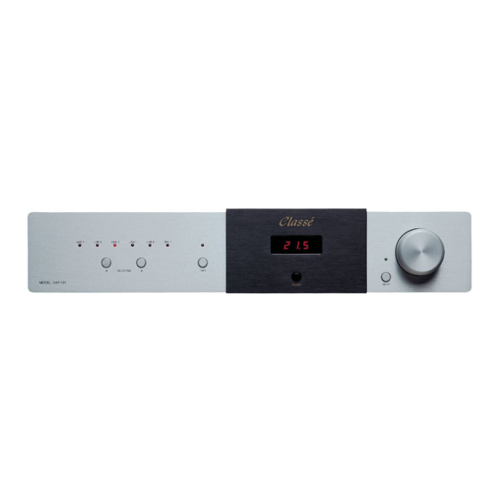
Protection Modes and Indicators The front LED display shows the status of the amplifier. When starting up normally, the CAP80 / CAP101 will show a countdown from 20 to 0. However, there is no protection on the CAP80 / CAP101. The CAP80 / CAP101 is equipped with four rail protection fuses. -
Page 7: Troubleshooting Guide
Troubleshooting Guide Symptom Possible cause Unit won’t turn on Check connections; Check fuses; Check soft-start circuit; Check relays; Check power supply circuits (positive rail, negative rail, Mosfet supply). Smoked and/or burned Check for short between components and ground; components Check output transistors; Check output relays;... -
Page 8: Output Transistors Testing And Replacement
Output Transistors Testing and Replacement PLEASE NOTE THAT THESE TESTS ARE ONLY EFFECTIVE ON BIPOLAR TRANSISTORS. DO NOT PERFORM THESE TESTS ON MOSFET DEVICES, AS THEY ARE LIKELY TO BECOME SHORT DURING THE TEST. You should check all pin combinaisons, as there is a chance that only one side of the transistor is short. When replacing outputs transistors, the technician should first disconnect both outputs and main board to check if the blown outputs were caused by a faulty component on the amplifier’s base. -
Page 9: Calibrations And Adjustments
Calibrations and Adjustments Bias adjustment: Note: Bias adjustment should be made without any load connected to the amplifier’s output, and no signal connected to the amplifier’s input. 1. Since it is impossible to connect a multimeter to both emitter’s resistors in order to measure and adjust bias without disassembling the heatsink from the chassis, we provided a test point to ease the bias procedure. -
Page 10: Parts List
Classe Audio with the part location, PCB number, and model and serial number of the unit. If you need a complete PCB, please replace the (x) in the Classe part number with the revision number printed on the board. -
Page 11: Updates
Updates 1. On board B154X, replace R122, R126, R222 and R226 with Classe part number RN55D7680. 2. On board B154X, replace RV101 and RV201 with Classe part number 3299W-1-202. 3. On board B154X, replace R134 and R234 with Classe part number A211-1004. -
Page 12: Fuses
DISTORTION ON TOP OF THE SIGNAL. Main fuses: For 100 – 120v units: 4A slo-blo, Classe part number GDC-4A For 220 – 240v units: 3.15A slo-blo, Classe part number GDC-3.15A The main fuse is located at the back of the unit, on the rear panel. -
Page 13: Voltage Change
INCANDESCENT BULB. 1. Set the primary wires of the main transformer as described below. 2. Replace the varistor, according to new line voltage, following Classe’s recommendations. If varistor is not available, remove old varistor and leave it empty. 3. Set the jumpers accordingly on the auxiliary transformer located at the back of the unit on the top... -
Page 14: Ir Interface Information
IR Interface Information Press and hold: LINE 1 = Turns on Amplifier # 1 LINE 2 = Turns on Amplifier # 2 LINE 3 = Turns on Amplifier # 3 BAL 1 = Turns on Amplifier # 4 BAL 2 = Turns on Amplifier # 5 BAL 3 = Turns on Amplifier # 6... - Page 19 B154XR08.sch-1 - Mon Aug 20 08:51:40 2007...
Need help?
Do you have a question about the CAP-80 and is the answer not in the manual?
Questions and answers