
Related Manuals for MAXDATA Belinea 101725


Summary of Contents for MAXDATA Belinea 101725
-
Page 1: Service Manual
Service Manual Model : Belinea 101725 Art. No. 111707 MAXDATA Systeme GmbH Elbestr. 12-16 45768 Marl / Germany... -
Page 2: Table Of Contents
Contents 1. Precautions Safety Precautions Servicing Precautions Electrostatically Sensitive Devices (ESD) Precautions 2. Product Specifications Specifications Dimensions Pin Assignment Table D-Sub 15 Pin Connector Timing Chart 3. Disassembly and Reassembly 4. Troubleshooting No Power No Video No Picture No Sound 5. - Page 3 Key PCB Semiconductor Aead Identification 11. Schematic Diagram Copyright 2003 by Maxdata Systeme GmbH All rights reserved. This manual may not, in whole or in part, be copied, photocopied, reproduced, translated, or converted to any electronic or machine readable form without prior written permission of Maxdata Systeme GmbH.
-
Page 4: Precautions
Precautions 1. Precautions Follow these safety, servicing and ESD precautions to prevent damage and to protect against potential hazards such as electrical shock. 1-1 Safety Precautions 1-1-1 Warnings 1. For continued safety, do not attempt to modify the circuit board. 2. - Page 5 Precautions c. Use a SSVM or VOM with 1000 ohms per-volt or higher sensitivity to measure the AC voltage drop across the resistor (see Figure 1-1). d. Connect the resistor to an exposed metal part having a return path to the chassis(metal cabinet, screw heads, knobs, shafts, escutcheon, etc.) and measure the AC voltage drop across the resistor.
-
Page 6: Servicing Precautions
Precautions 1-2 Servicing Precautions WARNING : An electrolytic capacitor installed with the wrong polarity might explode. Caution : Before servicing instruments covered by this service manual and its supplements, read and follow the Safety Precautions section of this manual. Note : If unforeseen circumstances create conflict between the following servicing preautions and any of the safety precautions, always follow the safety precautions. -
Page 7: Electrostatically Sensitive Devices(Esd) Precautions
Precautions 1-3 Electrostatically Sensitive Devices(ESD) Precautions Some semiconductor (solid state) devices can be easily damaged by static electricity. such components are commonly called Electrostatically Sensitive Devices(ESD). Examples of typical ESD devices are integrated circuits and some field-effect transistors. The following techniques will reduce the incidence of component damage caused by static electricity. -
Page 8: Product Specifications
Precautions 2. Product Specifications 2-1 Specifications Model Belinea 101725 Type Amorphous Active Matrix Super TFT LCD Screen Size 43.2cm ( Diagonal ) Maximum Resolution 1280 X 1024 @ 75Hz Pixel Range 0.264mm X 0.264mm LCD PANEL Display Colors 16.2M Contrast Rate... -
Page 9: Timing Chart
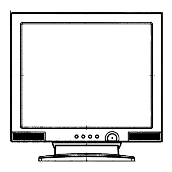
Product Specifications 2-2 Pin Assignment The 15-pin D-sub connector(male) of the signal cable(IBM systems) Pin No Assignment Pin No Assignment Red Video 5V Input Green Video Ground Blue Video Ground SDA (DDC Data) Ground H-Sync Red Video Ground V-Sync Green Video Ground SCL (DDC Clock) Blue Video Ground 2-3 Timing chart... - Page 10 Product Specifications 2-4 Dimensions FRONT VIEW SIDE VIEW REAR VIEW Service Manual...
-
Page 11: Disassembly And Reassembly
3. Disassembly and Reassembly The section of the service manual describes the disassembly and reassembly procedure for the Belinea 101725 Monitor. WARNING : This has to be disassembled and reassembled carefully because TFT-LCD Panel is weak for impact. This monitor contains electrostatically sensitive devices. - Page 12 Disassembly and Reassembly Figure 111707 Service Manual...
- Page 13 Disassembly and Reassembly 3-2 Reassembly 3-2-1 Display part Reassembly As you reassemble reversely the display part dissambly method, confirm that insulation plate puts into on the left of the TFT-LCD panel and main chassis. 3-2-2 Display part and Stand part Reassembly Reassembly reversely the Multimedia Stand part disassembly method.
-
Page 14: Troubleshooting
Troubleshooting 4. Troubleshooting 4-1 No Power Does proper DC 5V appear at Check Combo board and pin2, pin3 of CN1 combo harness Does proper DC 3.3V appear at Check U6 and pin 4 of U1 related circuit of U7 Does proper DC 2.5V appear at Check U2 and Pin 4 of U2 related circuit of U2... -
Page 15: No Video
Troubleshooting 4-2 No Video brinking It indicates the monitor is in power Check the Power indicating LED saving mode Green Does proper DC 5V appear at Check U600 and related circuit of U600 pin 2,3 of U600 Does proper signal appeear at Check CN100 and related circuit Pin 127,131,135,100,101 of of CN100... -
Page 16: No Sound
Troubleshooting 4-3 No Sound Check Phone Jack(J400) Check Phone Jack(J400)& Stereo Cable. Signal. Dose proper DC 12V appear at Check Combo board and combo harness pin 15,16 of U400(TDA7496) Dose proper signal output Check U400 and related circuit of U400 appear at pin 14, 17 of U400 Dose proper signal output Check CN401 and related circuit of... -
Page 17: Exploded View & Parts List
Exploded View & Parts List 7. Exploded View & Parts List 16-E 16-D 16-C 16-B 16-A 15-D 15-C 15-B 15-A 111707 Service Manual... - Page 18 Exploded View & Parts List PART NAME CODE NO. DESCRIPTION Q’TY REMARKS BEZEL FRONT ASS'Y 6526170009AD BEZEL FRONT 6226170014AD H750,OEM,MAXDATA, SILVER(B2050),ABS-HB,SD-0150,C7425 LENS,POWER 6226170020AD H750/H550,OEM,PMMA KNOB CONTROL 6226170030AD H750,OEM,MAXDATA, SILVER(B2050),ABS-HB,SD-0150,C7425 SPEAKER 56410003AAAD NB-04301-15,1 INCH,8 OHM, 350HZ,1.0W T/T,SCREW 67613004AAAD BHB,+,3 8,.,." 17""TFT-LCD PANEL 5417L00814AD LTM170EU-L01,LVDS,8BIT,16.2M,...
-
Page 19: Packing & Unpacking
Packing & Unpacking 6. Packing & Unpacking Description Specification Quantity Remarks Tape-Masking OPP W75 CLR 1.2 Mt Carton Box CB DW-3 Belinea 101725 Set-Monitor 1Set EPS 60M C=0.018 Belinea 101725 Cushion-L/R 1Set 17" TFT Monitor Belinea 101725 Gift Box Cable Etc. -
Page 20: Electrical Parts List
Electrical Parts List Introduction 7. Electrical Parts List 7-1. MAIN BOARD LOCATION No. PART NO. TYPE DESCRIPTION CE1,CE2,CE5,CE6,CE205,CE600 276604763CHD CAP, CAN-ELECT,G.P 47UF, 16V, 20%, CASE:6.3X5, -40 ~ +85 ,SMD CE3,CE4 276601073CHD CAP, CAN-ELECT, G.P 100UF, 16V, 20%, CASE:6.3X6, -40 ~ +85 ,SMD CE7,CE200,CE201,CE202,CE203,CE204 276602263CHD CAP, CAN-ELECT,G.P... - Page 21 Electrical Parts List LOCATION No. PART NO. TYPE DESCRIPTION X200 3120014318MD CRYSTAL REV.01, 14.318MHZ,33PF, 30PPM,TS-1 TYPE,SMD CE400,CE401,CE402,CE403 276602273CTD CAP,CAN-ELECT,GP 220UF,16V,20%,CASE:8*10,-40~+85'C,SMD C401,C402 26508R0474MD CAP, CERAMIC 0.47UF, 50V, +80%/-20%, Y5V, SMD, 1608 FB601,FB600 3222180002CD EMI FILTER BEAD,120 OHM,200MA,SMD,1608 Q400,Q401,Q601 303900031ACB TR, NPN REV.01, MMBT3904 LTI,3P,SOT-23 R114,R115,R116 21705607ASTD...
-
Page 22: Osd Key Board
Electrical Parts List 7-2. OSD KEY BOARD LOCATION No. PART NO. TYPE DESCRIPTION ZD500,ZD501,ZD502,ZD503,ZD504,ZD505, 3531001492TD DIODE, ZEN MTZJ 5.1B/UZ-5.1BSB, 5.1V, 5MA, 500MW,T-72, AT ZD506,ZD507 SW501,SW502,SW503,SW504,SW505, 58210006RAAD SWITCH,TACT DHT-1105TABF,2P, SW506,SW507 RESET S/W,DC12V,50MA,5MM,TAPING,H530 D504 3541000311TD DIODE, LED REV.01, SM3411/HB3B-243, 85MW, 30MA, GREEN, TAPING 4922120061KD HARNESS,KEY CABLE ASS'Y 9*10P(SMH200-08,... - Page 23 Block Diagram Block Diagram 8. Block Diagram 111707 Service Manual 111707 Service Manual...
- Page 24 Wiring diagram Wiring diagram 9. Wiring diagram 111707 Service Manual 111707 Service Manual...
-
Page 25: Main Pcb
PCB Layout PCB Layout 10. PCB Layout 10-1. Main PCB 111707 Service Manual 111707 Service Manual... - Page 26 PCB Layout PCB Layout 10-2. Key PCB 10-3. Key PCB (OEM) 10-4. Semiconductor Lead Identification. PARTS TYPE NO. REF NO. Q400, Q401, Q402, Q601 MMBT3904 BZX84 D101, D102, D103, ZD107, ZD108 BAT54 D100 BAV99 D104, D105, D106 U201 GM2121 U601 KIA7025 U202 W29EE011...
- Page 27 Schematic Diagrams Schematic Diagrams 11. Schematic Diagrams 11-1. Main Board 111707 Service Manual 111707Service Manual...
- Page 28 Schematic Diagrams Schematic Diagrams 11-1. Main Board 111707 Service Manual 111707 Service Manual...
- Page 29 Schematic Diagrams Schematic Diagrams 11-1. Main Board 111707 Service Manual 111707 Service Manual...
- Page 30 Schematic Diagrams Schematic Diagrams 11-1. Main Board 111707 Service Manual 111707 Service Manual...
- Page 31 Schematic Diagrams Schematic Diagrams 11-2. Key Control Board 111707 Service Manual 111707 Service Manual...
Need help?
Do you have a question about the Belinea 101725 and is the answer not in the manual?
Questions and answers