
Related Manuals for Samsung CKF5607L


Summary of Contents for Samsung CKF5607L
-
Page 1: Table Of Contents
COLOR MONITOR CKF5607L (SyncMaster 500b SERVICE Manual COLOR MONITOR CONTENTS 1. Precautions 2. Reference Information 3. Product Specifications 4. Operating Instructions 5. Disassembly & Reassembly 6. Alignment & Adjustments 7. Troubleshooting 8. Exploded View & Parts List 9. Electrical Parts List 10. - Page 2 Samsung Electronics Co., Ltd. March 1998 Printed in Korea Code No.: BH68-61036A...
-
Page 3: Precautions
Components identified by on schematics and parts leads are not pinched or that hardware is not lists must be sealed by a soldering iron after lodged between the chassis and other metal parts in replacement and adjustment. the monitor. CKF5607L... -
Page 4: Servicing Precautions
“anti-static” a carpeted floor can generate enough static can generate electrical charges sufficient to damage electricity to damage an ESD. ESDs. Indicates ESDs on the Schematic Diagram in this manual. CKF5607L... -
Page 5: Reference Information
Vertical Position H/PHONE Headphone V-SENSE Voltage-Sense Hertz V-SIZE Vertical Size I-SENSE Current-Sense R-Wire Wound Pound X-TAL Crystal Ω Maximum Microphone KΩ 1000 ohm Minimum MΩ 1000 KΩ C-Metalized Polyester microfarad (10 Metal Polypropylene nanofarad (10 R-Metal Oxide picofarad (10 CKF5607L... - Page 6 SWEDAC Electrostatically Sensitive Device Test Point Electronic Static Field Underwriters Laboratories Flyback Transformer Universal Serial Bus Field Effect Transistor VESA Video Electronics Standard Horizontal Frequency Association Fail Safe Video Graphics Array Vertical Frequency Variable Registor Geometric Distortion White Balance CKF5607L...
-
Page 7: Product Specifications
Storage Temperature : -4°F to 113°F (-20°C to 45°C) Humidity : 5 % to 95 % • Above models comply with SWEDAC (MPR II) recommendations for reduced electromagnetic fields. • Designs and specifications are subject to change without prior notice. CKF5607L... -
Page 8: Pin Assignments
GND-G GND-G GND-G Sense 1 GND-B GND-B Reserved Reserved Reserved Blue GND-Sync/Self-raster GND-Sync/Self-raster Sense 2 DDC Data DDC Data V-Sync H-Sync H/V-Sync GND-B V-Sync Not Used DDC Clock DDC Clock H-Sync Figure 3-1. Male Type Figure 3-2. Male Type CKF5607L... -
Page 9: Timing Chart
B : Horizontal sync width O : Frame time total P : Vertical sync width C : Back porch D : Active time Q : Back porch R : Active time E : Front porch S : Front porch CKF5607L... - Page 10 3 Product Specifications Memo CKF5607L...
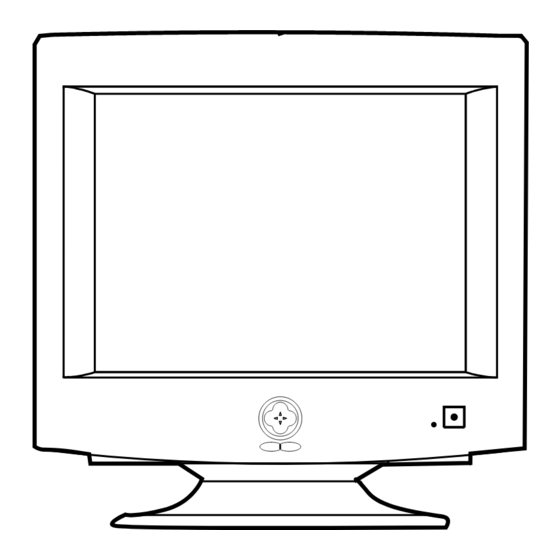
- Page 11 AC Cord Inlet Figure 4-2. Rear View Table 4-1. Front Panel Controls Location Symbol Description Power Button Power Indicator LED (Dual Color) Up Button Left Button Right Button Down Button Figure 4-1. Front Control Panel Exit Button Menu (↵) Button CKF5607L...
-
Page 12: Operating Instructions
E x i t : E x i t M e n u Figure 4-3. OSD Windows To access a function, use the buttons to move to its associated icon, and then use the button to highlight the adjustment type. Then, push the ↵ button to access the function. CKF5607L... -
Page 13: Power Management System
This system operates with a VESA DPMS program to enable the power saving compliant video card installed in your computer. function. Please contact Samsung or your You use a software utility installed on your dealer for more information. computer to set up this feature. See the table Note 3: For energy conservation, turn your below for details. - Page 14 4 Operating Instructions Memo CKF5607L...
-
Page 15: Disassembly And Reassembly
5 Disassembly and Reassembly This section of the service manual describes the disassembly and reassembly procedures for the CKF5607L monitor. WARNING: This monitor contains electrostatically sensitive devices. Use caution when handling these components. 5-1 Disassembly Cautions:1. Disconnect the monitor from the power source before disassembly. - Page 16 CN301, CN401, CN402 and CN403 connectors on the Main PCB. 7. Replace all easily accessible ground wires on the CRT GND Assembly and Bottom Chassis. 8. Replace the Degaussing Coil at CN600 on the Main PCB. 9. Replace the Anode Cap. CKF5607L...
-
Page 17: Alignment And Adjustments
53.6 kHz/85Hz. Horizontal: 30 kHz to 70 kHz (Automatic) Vertical: 50 Hz to 160 Hz (Automatic) Unless otherwise specified, adjust at the 800 x 600 mode (53.6 kHz/85 Hz) signals. Refer to Table 3-1 on page 3-3. CKF5607L... - Page 18 Computer with a video board that uses the ET-4000 chipset (strongly recommended if Figure 6-1. Setup 1, With Signal Generator using Samsung DM 200 software) and that displays: 1024 x 768 @ 85 Hz, or 800 x 600 @ 85 Hz (minimum).
-
Page 19: Display Control Adjustments
Maximum 4 : 3 Vertical : 15.5~17.9 Vertical : Less than 0.83 mm Click on the << or >> box next to V_SIZE to adjust the vertical size of the display pattern to 200 mm. (Tolerance: ± 3 mm.) CKF5607L... - Page 20 6 Alignment and Adjustments 6-2-2 (a) HORIZONTAL LINEARITY ADJUSTMENT 6-2-5 Parallelogram Adjustment The CKF5607L monitor offer only Vertical CONDITIONS Linearity adjustments. Horizontal Linearity is Scanning frequency: 53.6 kHz/85Hz fixed on the Chassis and is not adjustable. Brightness: Maximum Contrast: Maximum 6-2-2 (b) VERTICAL LINEARITY ADJUSTMENT Click on the <<...
-
Page 21: Color Adjustments
“x” coordinate to 0.283 ± 0.02. Note: If the above adjustments cannot be done to each coordinate, click on the << or >> box next to G_CUT to decrease or increase the green cutoff (bias) and repeat procedures 3 and 4. CKF5607L... - Page 22 2. Refer to the procedure for 9300K, section video satisfies the above spec. 6-3-2 (c) steps 2 and 3. If they do not, return to 6-3-2 (a) and readjust all settings. 6-3-3 (d) WHITE BALANCE ADJUSTMENT VERIFICATION Refer to the procedure for 9300K, section 6-3-2 (d). CKF5607L...
- Page 23 Conspicuous mislanding (unexpected color in a 7. When you have the PCMs properly adjusted, uniform field) within the display area shall not be carefully glue them together to prevent their visible at a distance of 50 cm from the CRT movement during shipping. surface. CKF5607L...
- Page 24 (change the spacing between tabs) to converge the vertical red and blue lines. 267 MM 4. Rotate the pair of rings (maintaining the Figure 6-12. Convergence Measurement Areas spacing between tabs) to converge the horizontal red and blue lines. CKF5607L...
- Page 25 Red and Blue Alignment Red, Blue and Green Alignment (4-pole magnet movement) (6-pole magnet movement) O-Magnetic VERTICAL Field MISALIGNMENT (1) SPREAD MAGNET HORIZONTAL MISALIGNMENT Motion (1) SHIFT DIRECTION OF CROSSHATCH PATTERN Motion (2) MOVE TOGETHER SHIFT DIRECTION OF CROSSHATCH PATTERN CKF5607L...
- Page 26 Bow convergence adjustments are not available Coil (X ). Turning it right raises the right end of for the CRTs used in the CKF5607L monitor. the blue line and lowers the left end. Turning the While all CRTs have bow convergence magnets,...
-
Page 27: Troubleshooting
Check T602 and D608. negative pole of C612? Check Power protection. Check IC602. WAVEFORMS 472V (T601 #5) 3.44 V (C612, –) CH1 P-P = 472 V CH1 RMS = 372.2 V CH1 P-P = 3.44 V CH1 RMS = 620 mV CKF5607L... - Page 28 Pin 1 of T401? WAVEFORMS 9.24 V (IC401, #26) 93.6 V (T401, #1) Check CN401, CN402, D409 and Q410 CH1 P-P = 9.24 V CH1 RMS = 6.048 V CH1 P-P = 93.6 V CH1 RMS = 55.2 V CKF5607L...
- Page 29 Does switching pulse appear at Check Q506, Q507, Q508 and Q509. base and collector of Q509? CH1 P-P = 952 V CH1 RMS = 307.2 V Does signal appear at gate Check IC501 and FBT. of Q512? Check Q512, D511, D508 and FBT. CKF5607L...
- Page 30 Does H/V sync pulse Check signal cable connection appear at Pins 4 and the signal sources. and 10 of IC104? Check IC104. Does H/V sync output appear at Pins 20 Check Micom and IC202. and 21 of IC202? Check IC401 CKF5607L...
-
Page 31: No Video
Pins 8, 9 and 11 of IC105? CH1 P-P = 3.34 V CH1 RMS = 3.088 V Check contrast circuit Replace the IC105. on the main Board (Q102 and Q513). Check DC 70 V at Pin 6 of IC105. CKF5607L... - Page 32 Does the OSD output Check IC102. CH1 P-P = 3.34 V CH1 RMS = 3.088 V signal appear at Pins 21, 22 and 23 of IC102? Check the pins of IC600 and the related circuit. OSD Gain (IC101 Pin 11) Check IC102. CKF5607L...
- Page 33 7-9 Degauss Operation Failure When you push the manual degauss button, Replace IC202. does 5 V appear at Pin 3 of IC202? When pushing the manual degauss button, does the Q600 Replace Q600. operate well? Check and replace if necessary RL601. CKF5607L...
- Page 34 LED Color Normal Active Active Active Green Stand-By Inactive Active Blank Amber Suspend Active Inactive Blank Green/Amber blinking Inactive Inactive Blank Amber blinking Note: If the signal cable is removed, DPMS function does not operate and a self raster displays. CKF5607L...
- Page 35 7 Troubleshooting 7-11 User Controls Don’t Work Does the DC level change at Pins Check the buttons. 13 and 14 of IC201 when you push (SW1 ~ SW6) the front panel button? Check IC202, Q202 and RESET circuit. CKF5607L...
- Page 36 7 Troubleshooting Memo 7-10 CKF5607L...
-
Page 37: Electrical Parts List
CAP-AL.ELEC,107M,1C (T)16V 100M C403 64.5 121.5 2201-000009 C-CERAMIC,DISC 22pF,5%,50V,NPO,4x3.5,5,TP C404 56.3 121.4 2201-000009 C-CERAMIC,DISC 22pF,5%,50V,NPO,4x3.5,5,TP C405 43.1 139.3 2301-000168 C-FILM,PEF 150nF,5%,100V,11.5x19mm,7.5mm C406 28.5 134.3 2401-000031 (T)16V 47M CAP-AL.ELEC,476M,1C C407 140.5 2305-000001 C-FILM,MPEF 470nF,10%,63V,6.0X15.5X7.5,5mm C408 66.3 161.6 2301-000016 C-FILM,PEF 22nF,5%,100V,7.2x4.5x9.0mm,5mm CKF5607L... - Page 38 22uF,20%,50V,GP,6.3x11mm,5mm,T C503 222.7 133.3 2401-000032 (T)50V 100M CAP-AL.ELEC,107M,1H C504 272.8 143.2 2303-000145 C-FILM,PPF 1nF,10%,2KV,23x13mm,7.5mm,TP C505 231.4 141.8 2306-000007 C-FILM,MPEF 470nF,5%,250V,21.5X13.0X7.9,17 C506 281.9 225.2 2401-000638 C-AL 2.2uF,20%,350V,WT,10x12.5mm,5m C507 267.4 161.1 2401-000026 (T)50V 3.3M CAP-AL.ELEC,335M,1H C508 288.5 213.8 2201-000285 C-CERAMIC,DISC 1nF,10%,1KV,Y5P,8.0X4.0,5,TP CKF5607L...
- Page 39 CAP-AL.ELEC,157M (T)150UF,63V,20%.1J,10X20,R-RADIAL C622 86.3 78.9 2401-000041 C-AL 220uF,20%,16V,GP,10x12.5mm,5mm C623 150.3 14.1 2301-000011 C-FILM,PEF 1nF,5%,100V,10.5x12.5x6.5,5mm C624 140.9 17.3 2301-000287 (T)100V 562J CAP-MYLAR,562J,2A,5P C625 2305-000280 C-FILM,PEF 220NF, 10%, 63V,7.5X13.5mm,5mm,T C626 2301-000013 C-FILM,PEF 4.7nF,5%,100V,10.5x12.5x6.5,5m C627 2201-000291 CAP-CERAMIC,102K,2H,Y5P 1NF,500V,20%,10%,Y5P,DISC-RADIA C628 2201-000291 CAP-CERAMIC,102K,2H,Y5P 1NF,500V,20%,10%,Y5P,DISC-RADIA CKF5607L...
- Page 40 178.6 0402-001131 DIODE-RECTIFIER UG1B,100V,1A,DO-204AL,TP D405 112.8 209.5 0402-000274 400V,1A,1V,1A,50NS,0.5A DIODE-REC,UF4004,DO-41 D407 63.9 181.6 0401-000006 DIODE-SWITCHING BAV21,200V,250mA,400mW,50nS,DO D408 34.8 168.5 0401-000005 75V,150MA,1V,10MA DIODE-SIG,1N4148,DO-35 D409 217.1 0402-001046 DIODE-RECTIFIER 1500V,10A,TO220F,ST D501 296.2 168.9 0401-000005 75V,150MA,1V,10MA DIODE-SIG,1N4148,DO-35 D503 299.5 201.8 0401-000005 75V,150MA,1V,10MA DIODE-SIG,1N4148,DO-35 CKF5607L...
- Page 41 IC-EEPROM 24LC21,128X8BIT,DIP,8P,300MIL IC205 45.8 76.6 1103-001020 IC-EEPROM 24LC04,4Kx8BIT,DIP,8P,300MIL IC300 96.5 51.8 1204-000013 IC-CONSUMER/CIRCUIT 9302,TO-220,7P,15V/30V,VERTIC IC401 1204-001231 IC-DEF. PROCESSOR TDA9109,DIP,32P,300MIL,PLASTIC IC501 138.1 1203-000182 IC-POSI.ADJUST REG. 494,DIP,16P,300MIL,PLASTIC IC502 95.9 151.2 1201-000420 IC-OP AMP 358,DIP,8P,300MIL,DUAL,100V/mV IC600 90.3 92.8 1203-000001 IC-POSI.ADJUST REG. 7805,TO-220,3P,PLASTIC,4.8/5 CKF5607L...
- Page 42 0.625W,75V,40V,6V,0.6A TR-NPN,MPS2222A,TO-92,EBC Q511 141.8 156.1 0501-000303 0.25W,-60V,-50V,-5V,-0.15A TR-PNP,KSA733,TO-92,EBC Q512 206.4 143.3 0505-001181 FET-SILICON IRF634A,N,250V,8.1A,450mohm,74 Q513 279.3 160.7 0501-000303 0.25W,-60V,-50V,-5V,-0.15A TR-PNP,KSA733,TO-92,EBC Q600 208.7 99.4 0501-000389 TR-SMALL SIGNAL KSC815,NPN,400mW,TO-92,TP,120- Q601 0501-000321 TR-SMALL SIGNAL KSB1116-Y,PNP,0.75W,TO-92,13 Q602 99.8 89.9 0501-000389 TR-SMALL SIGNAL KSC815,NPN,400mW,TO-92,TP,120- CKF5607L...
- Page 43 R256 2001-000067 REF-CF,10K,5%,1/6W 150V,-1300 TO +350PPM/C,R-AXIAL R257 2001-000053 REF-CF,3.3K,5%,1/6W 150V,-1300 TO +350PPM/C,R-AXIAL R258 2001-000074 REF-CF,33K,5%,1/6W 150V,-1300 TO +350PPM/C,R-AXIAL 150.6 91.3 2001-000059 R-CARBON 5.6Kohm,5%,1/6W,AA,TP,1.8x3.2m R301 117.3 50.2 2001-000245 REF-CF,1.5,5%,1/2W 350V,-350 TO +350PPM/C,R-AXIAL R302 114.4 45.1 2001-000067 REF-CF,10K,5%,1/6W 150V,-1300 TO +350PPM/C,R-AXIAL CKF5607L...
- Page 44 250V,-350 TO +350PPM/C,R-AXIAL R437 105.7 222.3 2001-000037 REF-CF,330,5%,1/2W(S) 300V,-200 TO +200PPM/C,R-AXIAL R438 102.9 222.2 2001-000084 REF-CF,100K,5%,1/4W 250V,-600 TO -150PPM/C,R-AXIAL R439 149.3 221.1 2001-000037 REF-CF,330,5%,1/2W(S) 300V,-200 TO +200PPM/C,R-AXIAL R440 78.1 231.5 2003-000767 REF-MO,680,5%,2W(S) 350V,-350 TO +350PPM/C,R-AXIAL R441 127.7 2003-000710 R-METAL OXIDE(S) 47ohm,5%,2W,AA,TP,4x12mm CKF5607L...
- Page 45 R529 136.7 2001-000057 REF-CF,5.1K,5%,1/6W 150V,-1300 TO +350PPM/C,R-AXIAL R534 303.2 222.9 2001-000546 R-CARBON 270Kohm,5%,1/4W,AA,TP,2.4x6.4m R535 283.3 124.4 2001-000562 R-CARBON 27Kohm,5%,1/6W,AA,TP,1.8x3.2mm R536 302.4 209.9 2001-000067 REF-CF,10K,5%,1/6W 150V,-1300 TO +350PPM/C,R-AXIAL R537 2001-000056 REF-CF,4.7K,5%,1/6W 150V,-1300 TO +350PPM/C,R-AXIAL R538 297.2 233.9 2001-000086 R-CARBON 100Kohm,5%,1/6W,AA,TP,1.8x3.2m CKF5607L...
- Page 46 R-CARBON(S) 220ohm,5%,1/2W,AA,TP,2.4x6.4mm R646 307.3 177.5 2001-000026 REF-CF,75,5%,1/6W 150V,-1300 TO +350PPM/C,R-AXIAL R647 307.3 190.5 2001-000026 REF-CF,75,5%,1/6W 150V,-1300 TO +350PPM/C,R-AXIAL R648 307.3 2001-000026 REF-CF,75,5%,1/6W 150V,-1300 TO +350PPM/C,R-AXIAL R649 307.3 2001-000026 REF-CF,75,5%,1/6W 150V,-1300 TO +350PPM/C,R-AXIAL RL401 91.8 219.2 3501-001064 RELAY-POWER 12Vdc,0.36W,2A,1FormC,10mS,5mS 9-10 CKF5607L...
- Page 47 BH26-20336D TRANS-POWER 470uH/250uH,18P,EI3942,PL-3,7u T602 182.7 BH26-30302S TRANS-SYNC. 3-1(250UH),SB-5S,UU1116,3- TH601 286.1 86.6 1404-000002 THERMISTOR-NTC 9OHM,20% TH602 243.8 56.2 1404-001020 THERMISTOR-NTC 8ohm,15%,17mW/C,BK VR501 226.1 232.6 2103-000454 VR-SEMI 50Kohm,25%,0.3W,SIDE X201 45.5 27.1 2801-003413 CRYSTAL-UNIT 24MHz,30ppm,28-ABQ,18pF,20ohm ZD127 305.2 162.9 0403-000005 0.5W,10MA DIODE-ZEN,UZ-5.1B,DO-35 CKF5607L 9-11...
- Page 48 45.6 2202-002008 C-CERAMIC,MLC-AXIAL 10nF,+80-20%,50V,Y5V,2.3X3.0 CG03 42.5 60.8 2202-002009 C-CERAMIC,MLC-AXIAL 100nF,+80-20%,50V,Y5V,2.3X3.0 CG04 65.6 98.9 2305-000009 C-FILM,MPEF 100nF,5%,250V,13x11x6.5,7.5mm CN101 56.5 3711-003133 CONNECTOR-HEADER BOX,13P,1R,2.5mm,STRAIGHT,SN CN102 28.1 3711-000044 CONNECTOR-HEADER BOX,6P,1R,2.5mm,STRAIGHT,SN CN103 44.2 27.4 3712-000338 CONNECTOR-TERMINAL PIN,MALE,2.36mm CN104 83.6 60.1 3712-000338 CONNECTOR-TERMINAL PIN,MALE,2.36mm CKF5607L 9-12...
- Page 49 150V,-1300 TO +350PPM,R-AXIAL R105 52.9 2001-000067 R-CARBON 10Kohm,5%,1/6W,AA,TP,1.8x3.2mm R107 2001-000464 REF-CF,2.4K,5%,1/6W 150V,-1300 TO +350PPM/C,R-AXIAL R108 111.7 31.5 2001-000097 REF-CF,1M,5%,1/6W 150V,-1300 TO +350PPM/C,R-AXIAL R109 2001-000059 REF-CF,5.6K,5%,1/6W 150V,-1300 TO +350PPM/C,R-AXIAL R110 83.8 12.7 2001-000051 R-CARBON 2.7Kohm,5%,1/6W,AA,TP,1.8x3.2m R111 90.6 2001-000056 R-CARBON 4.7Kohm,5%,1/6W,AA,TP,1.8x3.2m 9-13 CKF5607L...
- Page 50 RG04 44.2 71.3 2001-000301 REF-CF,10,5%,1/6W 150V,-1300 TO +350PPM/C,R-AXIAL RG05 38.9 65.8 2001-000652 R-CARBON 330ohm,5%,1/6W,AA,TP,1.8x3.2mm RG06 47.2 93.5 2001-000021 R-CARBON 27ohm,5%,1/4W,AA,TP,2.4x6.4mm RG07 81.9 98.6 2001-000547 R-CARBON 270Kohm,5%,1/6W,AA,TP,1.8x3.2m RG08 73.3 79.8 2001-000028 R-CARBON(S) 100ohm,5%,1/2W,AA,TP,2.4x6.4mm RR03 90.6 38.3 2001-000077 R-CARBON 47Kohm,5%,1/6W,AA,TP,1.8x3.2mm CKF5607L 9-14...
- Page 51 SK101 44.3 4715-000001 SURGE ABSORBER 1KV,+50-10% SK102 71.7 64.3 4715-000001 SURGE ABSORBER 1KV,+50-10% SK103 63.1 52.4 3704-001042 SOCKET-CRT 7P,22.5PI,12PI,SN SK104 63.8 69.5 4715-000001 SURGE ABSORBER 1KV,+50-10% SK105 56.2 4715-000001 SURGE ABSORBER 1KV,+50-10% SK106 77.2 4715-000001 SURGE ABSORBER 1KV,+50-10% 9-15 CKF5607L...
- Page 52 ASS’Y PCB CKF5607T1D,RUSSIA SESPO B/D ASS’Y CODE BH98-10011W ASS’Y PCB MAIN CKF5607LXX/CNT,TSED CHINA BH98-10010H ASS’Y PCB MAIN CKF5607 BH98-10011N ASS’Y PCB MAIN CKF5607T1D BH98-10011Z ASS’Y PCB MAIN CKF5607T1D,RUSSIA SESPO BH98-20004N ASS’Y PCB VIDEO CKF5607 BH98-50001Z ASS’Y PCB CONTROL CKF5607L 9-16 CKF5607L...
-
Page 53: Block Diagram
10 Block Diagram CKF5607L 10-1... - Page 54 10 Block Diagrams Memo 10-2 CKF5607L...
-
Page 55: Pcb Diagrams
2 : Vout, IRF634 Q512 3 : GND, CD74HC714E IC104 4 : Vcc LM324 IC103 KA2S0680 IC602 IRFR/U230A Q405, Q408 TL494 IC501 G D S 1 : Drain, 2 : GND, 3 : Vcc, 4 : F/B, 5 : Sync CKF5607L 11-1... - Page 56 11 PCB Diagrams Memo 11-2 CKF5607L...
-
Page 57: Wiring Diagram
@@@@@ PPPPP QQQQQ @@@@@@@@@@ PPPPPPPPPP @@@@@@@@@@ PPPPPPPPPP @@@@@@@@@@ PPPPPPPPPP QQQQQQQQQQ V – V – (BROWN) TCO + TCO + CN403 AC INPUT TCO + TCO + IS601 (TCO) TCO – (GND) TCO – (GND) (POWER INPUT) AC INPUT CKF5607L 12-1... -
Page 58: Schematic Diagrams
13 Schematic Diagrams 13-1 Power/Micom/Vert/V_Input Part Schematic Diagram SHEET1 13-1 CKF5607L... - Page 59 800 x 600 / 85 Hz 640 x 480 / 60 Hz 800 x 600 / 85 Hz 640 x 480 / 60 Hz 1.34 600 mV 1.41 1.67 10.95 5.92 5.96 19.10 19.01 1.32 1.50 330.2 321.2 13.12 12.24 –10.5 –10.56 Unit: Vrms 13.25 12.90 Unit: Vrms CKF5607L 13-2...
- Page 60 13 Schematic Diagrams 13-2 H-Defl/High-Voltage Part Schematic Diagram SHEET2 13-3 CKF5607L...
- Page 61 CH1 RMS = 71.84 V CH1 P-P = 56.8 V CH1 RMS = 18.42 V 3.696 3.772 8 mV 8 mV 13.15 13.17 398 V (T502, #1) Unit: Vrms CH1 P-P = 398 V CH1 RMS = 126.0 V CKF5607L 13-4...
- Page 62 13 Schematic Diagrams 13-3 Video_Output Part Schematic Diagram SHEET3 13-5 CKF5607L...
- Page 63 51.20 50.08 2.74 2.76 50.72 49.44 2.74 2.76 50.04 48.72 12.14 12.08 2.78 2.72 2.44 2.48 2.76 2.76 2.36 2.50 8.74 8.70 12.08 12.10 8.88 8.90 2.48 2.56 2.76 2.68 71.32 71.12 2.78 2.72 Unit: Vrms Unit: Vrms CKF5607L 13-6...
- Page 64 13 Schematic Diagrams Memo 13-7 CKF5607L...