New Yorker FR SERIES Installation, Operating And Service Instructions
Fr series horizontal tube boiler
Hide thumbs
Also See for FR SERIES:
- Installation, operating and service instructions (40 pages) ,
- Operating instructions manual (40 pages)
Table of Contents
Advertisement
INSTALLATION, OPERATING
AND SERVICE INSTRUCTIONS
HORIZONTAL TUBE BOILER
As an ENERGY STAR
New Yorker Boiler Co., Inc.
has determined that the
FR-HGS, FR-HGSII, FR-98,
FR-122, FR-147, FR-173, FR-205
and FR-232 water boilers
meet the ENERGY STAR
guidelines for Energy
efficiency established by the
United States Environmental
Protection Agency (EPA).
F
r o
s
e
v r
c i
e
r o
e r
p
i a
b
i o
e l
, r
p
o r
v
d i
e
B
o
l i
B
o
l i
r e
M
o
d
l e
N
u
m
b
F
R
H
e
t a
n i
g
C
o
t n
a r
t c
r o
A
d
d
e r
s
s
104183-02 - 7/12
FR™ SERIES
Partner,
®
®
s r
o t
b
i o
e l
, r
c
a
l l
o y
r e
M
o
d
l e
N
u
m
b
r e
a
n
r e
B
o
l i
r e
r u
h
e
t a
n i
g
c
o
t n
a r
c
o t
d
S
e
i r
l a
N
u
m
b
r e
a
s
S
e
i r
l a
N
u
m
b
r e
. r
W
h
e
n
s
e
e
k
n i
g
i
f n
r o
s
h
o
w
n
o
n
R
t a
n i
g
L
I
s n
a t
l l
t a
o i
n
D
P
h
o
n
e
N
u
m
b
m
t a
o i
n
o
n
a
b
e
. l
a
e t
r e
Price - $5.00
Advertisement
Table of Contents

Related Manuals for New Yorker FR SERIES


Summary of Contents for New Yorker FR SERIES
- Page 1 INSTALLATION, OPERATING AND SERVICE INSTRUCTIONS FR™ SERIES HORIZONTAL TUBE BOILER As an ENERGY STAR Partner, ® New Yorker Boiler Co., Inc. has determined that the FR-HGS, FR-HGSII, FR-98, FR-122, FR-147, FR-173, FR-205 and FR-232 water boilers meet the ENERGY STAR ®...
- Page 2 IMPORTANT INFORMATION - READ CAREFULLY All boilers must be installed in accordance with National, State and Local Plumbing, Heating and Electrical Codes and the regulations of the serving utilities. These Codes and Regulations may differ from this instruction manual. Authorities having jurisdiction should be consulted before installations are made.
- Page 3 DANGER DO NOT store or use gasoline or other flammable vapors or liquids in the vicinity of this boiler or any other appliance. WARNING Improper installation, adjustment, alteration, service or maintenance can cause property damage, personal injury or loss of life. Failure to follow all instructions in the proper order can cause personal injury or death.
-
Page 4: Table Of Contents
WARNING This boiler contains very hot water under 12 - 15 PSI pressure. DO NOT unscrew any pipe fittings nor attempt to disconnect any components of this boiler without positively assuring the water is cool and has no pressure. Always wear protective clothing and equipment when installing, starting up or servicing this boiler to prevent scald injuries. -
Page 5: General Information
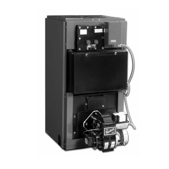
I: GENERAL INFORMATION Figure 1A: FR-HGS and FR-HGSII Water Boiler (Heat Only), Beckett Burner Figure 1B: FR-98-W Thru FR-232-W Water Boiler With or Without Tankless Heater, Beckett Burner... - Page 6 6-1/8 7-7/8 52.0 FR-350/400 25-7/8 27-7/8 35-3/4 40-7/8 6-1/8 9-7/8 70.0 FR-462 25-7/8 33-7/8 35-3/4 46-3/4 6-1/8 9-7/8 80.0 NOTE: 1. FR Series is available as a Packaged Water Boiler Only. 2. Maximum Working Pressure: Water 30 PSI Shipped Standard...
- Page 7 I: GENERAL INFORMATION (continued) TABLE 2: RATING DATA Burner Minimum Chimney AHRI AHRI NET Capacity Requirements Boiler Model Heating Gross AFUE % Ratings - Capacity - Output - (Thermal Effy) Round In. Rectangle Height Dia. In. x In. 0.80 8 x 8 87.8 * FR-HGS 1.00...
-
Page 8: Pre-Installation
II: PRE-INSTALLATION 3. FOR BASEMENT INSTALLATION, provide INSPECT SHIPMENT carefully for any signs of a solid elevated base, such as concrete, if floor is damage. not level, or if water may be encountered on floor 1. All equipment is carefully manufactured, inspected around boiler. - Page 9 II: PRE-INSTALLATION (continued) Locate remaining opening within 12 inches of PROVIDE COMBUSTION AND VENTILATION bottom of space. Minimum dimension of air opening AIR. Local and National Codes may apply and should is 3 inches. Size each opening per following: be referenced. a.
-
Page 10: Knockdown Boiler Assembly
III: KNOCK-DOWN BOILER ASSEMBLy INSTALLING THE JACKET REMOVAL OF BOILER from skid. 1. Remove all boiler-to-skid hold down fasteners. 1. Attach lower rear jacket panel to left side and right side jacket panels with the screws provided so that 2. FR-HGS thru FR-232: Carefully walk boiler to the the assembled components make a “U”... -
Page 11: Burner Mounting
III: KNOCK-DOWN BOILER ASSEMBLy (continued) Figure 4: Burner Mounting... -
Page 12: Water Piping And Trim
Oxygen contamination of boiler water will cause corrosion of iron and steel boiler components, and can lead to boiler failure. New yorker’s Standard Warranty does not cover problems caused by oxygen contamination of boiler water or scale (lime) build-up caused by frequent addition of water. - Page 13 IV: WATER PIPING AND TRIM (continued) Operate boiler until the system water temperature INSTALL DRAIN VALVE IN RETURN PIPING. reaches its normal operating range. Adjust See Figures 6A and 6B. the valves to maintain 180°F to 200°F boiler water temperature and greater the 120°F return OIL, GREASE, AND OTHER FOREIGN temperature.
- Page 16 IV: WATER PIPING AND TRIM (continued) of the available hot water by mixing some cold CONNECT TANKLESS HEATER PIPING AS water with the hot. This prevents the possibility SHOWN IN FIGURE 7. of scalding hot water at the fixtures. In addition, WARNING savings of hot water will be achieved since the user will not waste as much hot water while seeking a...
-
Page 17: Venting
V: VENTING GENERAL GUIDELINES means that the stack temperature from the 1. Vent system installation must be in accordance new boiler will be lower than that from the with these instructions and applicable provisions of old boiler and with less room air being drawn local building codes. - Page 18 V: VENTING (continued) Figure 9: Draft Regulator Locations...
-
Page 19: Electrical
VI: ELECTRICAL DANGER Positively assure all electrical connections are unpowered before attempting installation or service of electrical components or connections of the boiler or building. Lock out all electrical boxes with padlock once power is turned off. WARNING Failure to properly wire electrical connections to the boiler may result in serious physical harm. Electrical power may be from more than one source. - Page 22 VI: ELECTRICAL (continued) IGNITOR BL/WH IGNITOR L2 (IGN) BURNER MOTOR MOTOR L2 (MTR) NOTE: APPLY THIS BURNER SCHEMATIC TO APPROPRIATE LIMIT STEAM OR WATER BOILER T-T TERMINALS CONTROL SCHEMATIC, REFER TO FIGURES 10 AND 11 OIL SOLENOID VALVE VALVE CELL L2 (VLV) BURNER T-T JUMPER...
-
Page 23: Oil Piping
VII: OIL PIPING GENERAL SINGLE-PIPE OIL LINES 1. Use flexible oil line(s) so that burner door can 1. Standard burners are provided with single-stage be opened, or burner can be removed, without 3450 rpm fuel units with the bypass plug removed disconnecting the oil supply. - Page 24 VII: OIL PIPING (continued) TABLE 3: SINGLE STAGE UNITS (3450 RPM) TABLE 4: TWO-STAGE UNITS (3450 RPM) Two Pipe Systems Two Pipe Systems Maximum Length of Tubing Maximum Length of Tubing "H" + "R" (See Figure) "H" + "R" (See Figure) Lift "H"...
-
Page 25: System Start-Up
VIII: SySTEM START-UP WARNING All boilers equipped with burner swing door have a potential hazard which can cause severe property damage, personal injury or loss of life if ignored. Before opening swing door, turn off service switch to boiler to prevent accidental firing of burner outside the combustion chamber. - Page 26 VIII: SySTEM START-UP (continued) 3. WATER BOILERS WITHOUT TANKLESS fitting in a SOLID stream without air bubbles for HEATERS are equipped with an Intelligent Oil approximately 10 seconds. Boiler Control (Boiler Control). The Boiler Control 3. Close vent fitting and burner flame should start is factory programmed with a High Limit setpoint immediately after prepurge is completed.
- Page 27 VIII: SySTEM START-UP (continued) a. FR-HGS: features, Section XII, Paragraph I, Step 2. If the Beckett MB(L1) Head burners have a fixed head failure re-occurs, call your heating contractor which are non-adjustable. immediately before pressing the reset button. b. FR-HGSII thru FR-232-W: WARNING Beckett MD(V1) (variable) Head burners have the ability to control air by moving the head.
- Page 29 VIII: SySTEM START-UP (continued) motor, igniter, and valve are powered for four (4) minutes. The yellow light will be • At the end of four (4) minutes, the yellow light will turn off and the control will automatically return to standby mode. iii.
- Page 30 VIII: SySTEM START-UP (continued) • 3. CHECK OIL PRIMARY CONTROL Close hand valve in oil supply line. • Failure occurs, device enters Recycle Mode. CAUTION • Device tries to restart system after Due to the potential hazard of line voltage, only a approximately 60 seconds.
-
Page 31: Operating
IX: OPERATING WATER BOILERS SEQUENCE OF OPERATION 1. Water Boilers Without Tankless Heaters (Cold Start), Sequence Of Operation: a. The FR Boiler is equipped with an Intelligent Oil Boiler Control (boiler control). The boiler control replaces the traditional electronic aquastat and circulator relays and adds energy saving thermal purge features. - Page 32 IX: OPERATING (continued) d. If the thermostat is not satisfied and the “I” Press and release the key on the Boiler Control Operating Setpoint (SP) is reached the system to change from one parameter to the next. Each circulator will continue to operate and the burner setting will alternately flash between the relevant will stop.
- Page 33 IX: OPERATING (continued) c. Low Limit (LL_) Cold Start Boiler Control The Warm Start Boiler Control is factory Adjustment Mode Options programmed with a Low Limit Setpoint of 140-240°F Adjust High Limit Setting 110°F. On falling temperature the boiler 10-30°F Adjust High Limit Differential turns “on”...
- Page 34 IX: OPERATING (continued) TABLE 6: CIRCULATOR PRE-PURGE TIME EXAMPLE, i. ZC and ZR Terminal Function (ZC_) PARAMETER PP_= 2 MINUTES The boiler control allows configuration of the ZC output functionality to help the FR integrate ZC and ZR into each installation more effectively. The ZC Call for Boiler Boiler Status,...
- Page 35 IX: OPERATING (continued) TABLE 8: ZONE REqUEST, PARAMETER ZC_= ZR TABLE 9: EXTERNAL LOW LIMIT, PARAMETER ZC_= ELL Call for Heat Circulator Status Call for Heat Circulator Status Input Input Output Output Input Input Output Output ii. When ZC_ is set equal to Zone Request (ZR) STEAM BOILERS SEQUENCE OF OPERATION When there is no IWH the Cold Start Boiler Control “ZC”...
- Page 36 X: MAINTENANCE AND SERVICE INSTRUCTIONS WATER BOILERS: EXCESSIVE MAKE-UP WATER 1. Filling of boiler and system. A leaky system will increase the volume of make-up water supplied to the boiler, which can significantly GENERAL — In a hot water heating system, the shorten the life of the boiler.
-
Page 37: Boiler Cleaning
X: MAINTENANCE AND SERVICE INSTRUCTIONS (continued) 4. Always keep the manual fuel supply valve shut off WARNING if the burner is shut down for an extended period of time. This boiler contains controls which may cause 5. To recondition the heating system in the fall season the boiler to shut down and not restart without after a prolonged shut down, follow the instructions service. - Page 38 XI: BOILER CLEANING (continued) Figure 21: Cleaning of FR Boiler...
- Page 39 Important Product Safety Information Refractory Ceramic Fiber Product Warning: The Repair Parts list designates parts that contain refractory ceramic fibers (RCF). RCF has been classified as a possible human carcinogen. When exposed to temperatures about 1805°F, such as during direct flame contact, RCF changes into crystalline silica, a known carcinogen.
-
Page 40: Troubleshooting
XII: TROUBLESHOOTING COMBUSTION 6. WATER — Water in the fuel in large amounts will stall the fuel pump. Water in the fuel in smaller 1. NOZZLES — Although the nozzle is a relatively amounts will cause excessive wear on the pump, inexpensive device, its function is critical to the but more importantly water doesn’t burn. - Page 41 XII: TROUBLESHOOTING (continued) f. CAD cell defective. OIL PRIMARY CONTROL (Oil Primary) 1. Burner (Oil Primary) will not come on. g. Oil valve stuck open or closed. a. No power to Oil Primary. Note: The Safety Monitoring Circuit (SMC) is b.
- Page 42 XII: TROUBLESHOOTING (continued) b. If the Boiler Control detects an error it will flash "Err" (boiler control error) followed by a number. Use this text and number to identify the boiler problem and corrective action in Table 11 below. TABLE 11: BOILER CONTROL ERROR NUMBERS Display Status Recommended Corrective Actions...
-
Page 43: Repair Parts
All FR™ Series Repair Parts may be obtained through your local New Yorker Wholesale distributor. Should you require assistance in locating a New Yorker distributor in your area, or have questions regarding the availability of New Yorker products or repair parts, please contact: New Yorker Boiler Co., Inc., P.O. - Page 44 XIII: REPAIR PARTS (continued) Figure 22: Jacket Repair Parts...
-
Page 45: Jacket Assembly
1. Jacket Lower Front Panels on FR boilers equipped with burner swingdoor are constructed of three individual pieces. 2. Jacket sets for special builds may have unique panels not listed here. For special build parts contract New Yorker Boiler Co., Inc. Customer Service. - Page 46 NOTE: When ordering parts always give the serial number and model number shown on the boiler. Also provide the name of the part(s) shown below:...
-
Page 47: Bare Boiler Assembly
FR-98 and FR-122 7116037 Turbulators All Models Except FR-98 and FR-122 7116038 Notes: 1. Bare boiler parts for special builds may be different than those listed here. Contact New Yorker Boiler Co., Inc. Customer Service for special build boiler parts. - Page 48 XIII: REPAIR PARTS (continued) INSULATION REPLACEMENT KITS Combustion Chamber Insulation Replacement Kits Combustion Chamber Insulation Replacement Kits provide the floor insulation and the burner door insulation. FR Model(s) Kit Part Number FR-HGS/HGSII/98/122 62072001 FR-147/173 62072002 FR-205/232/265/305 62072003 FR-350/400 62072004 FR-462 62072005 Flue Box Insulation Replacement Kits Flue Box Insulation Replacement Kits provide the flue box door insulation, flue box frame top/bottom insulation...
- Page 50 XIII: REPAIR PARTS (continued) BECKETT BURNER PARTS LIST FOR FR SERIES STEEL BOILERS FOR REPLACEMENT OIL BURNER PARTS, CONTACT YOUR WHOLESALER OR THE BURNER MANUFACTURER: R. W. BECKETT CORP. P. O. BOX 1289 ELYRIA, OHIO 44036 1-800-645-2876 BECKETT AF and SF MODEL BURNERS...
-
Page 51: Burner Specifications
XIV: BURNER SPECIFICATIONS TABLE 12: BECKETT AFG & SF BURNER SPECIFICATIONS Settings Boiler Firing Rate Burner Static Nozzle Head Head Pump Model (GPH) Model Plate Shutter Band Bearing Pressure .65 x 60W FR-HGS* 0.80 140 PSI Delavan 3-3/8” U .85 x 60B FR-HGS 1.00 140 PSI... -
Page 52: Appendix A - Low Water Cut-Off
APPENDIX A: LOW WATER CUT OFF (LWCO) WARNING DO NOT ATTEMPT to cut factory wires to install an aftermarket Low Water Cut Off (LWCO). Only use connections specifically identified for Low Water Cut Off. In all cases, follow the Low Water Cut Off (LWCO) manufacturer's instructions. When minimum connection must have a... - Page 53 APPENDIX A: LOW WATER CUT OFF (LWCO) - continued How to Test A 24 VAC LWCO is used primarily for gas fired boilers where a 24 volt control circuit exists within the Shut off fuel supply. Lower water level until water boiler.
-
Page 54: Service Record
SERVICE RECORD DATE SERVICE PERFORMED... - Page 55 SERVICE RECORD DATE SERVICE PERFORMED...
- Page 56 These limited warranties apply to residential cast iron and steel water boilers including but not limited to the following: operated with insufficient water; labeled with the New Yorker ® brand which are sold on or after March 1, allowed to freeze; subjected to flood conditions; or operated with water conditions and/or fuels or additives which cause unusual deposits or corrosio 2004.
Need help?
Do you have a question about the FR SERIES and is the answer not in the manual?
Questions and answers