
Related Manuals for Philips SM40


Summary of Contents for Philips SM40
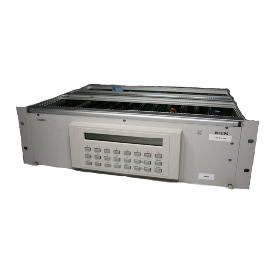
- Page 1 SM40 Sound Distribution System LBB 1350/30 Philips Communication & Security Systems...
-
Page 3: Important Safety Instructions
© 1997 All rights strickly reserved. Reproduction by third parties in any form is strickly forbidden, unless prior written authorisation has been given. In the continuing quest for product improvement Philips reserves the right to change the specification of any article or system without prior notice. - Page 4 SM40 SOUND DISTRIBUTION SYSTEM This page has been left blank intentionally...
-
Page 5: Table Of Contents
SM 40 BASIC SYSTEM AND EXTENSION FRAME Basic System - BS LBB 1350/30 Extension Frame - EF LBB 1360/30 OPERATING AND PROGRAMMING THE SM40 SYSTEM Central Processor Card - CPC Display and Keyboard - DK SM40 Programming 4.3.1 User Programming Menu 4.3.2... -
Page 6: General Introduction And Operating Principles
1. GENERAL INTRODUCTION AND OPERATING PRINCIPLES... -
Page 7: Introduction
LBB 1360 is available. This comprises: 1x power supply; 1x Interconnection Board; and 5x Termination Boards; tested and mounted in a 19 inch rack frame. 10 SM40 circuit cards fit into each Extension Frame, and these frames can be linked together to expand the system. - Page 8 1. GENERAL INTRODUCTION AND OPERATING PRINCIPLES...
- Page 9 (e.g. airports, sport stadiums). As an optional extra, an I/O -PCB is available, which allows the SM40 system to be coupled to a personal computer via a standard RS232 serial interface. Depending on the software applied the computer can be used in the ‘active’...
- Page 10 1. GENERAL INTRODUCTION AND OPERATING PRINCIPLES...
-
Page 11: Operating Principles
1. GENERAL INTRODUCTION AND OPERATING PRINCIPLES OPERATION PRINCIPLES The SM40 Public Address Distribution Centre is easy to use and logical in its operation, it is helpful however to understand, in principle, how the system works. Herewith a typical series of actions, initiated by the operator, and carried out by the system: User Key on Call Station (CST) is pushed (see Chapter 5.12). -
Page 12: Unpacking And Installation
2. UNPACKING AND INSTALLATION... -
Page 13: Power Supply Modules
Taking care to avoid earth (ground) loops, wire the mains power to the units. SM40 will operate successfully on mains voltages from 187 V to 264 V when tapped for 220 V, and from 90 to 132 V when tapped for 110 V. Be sure to check that your system is wired for the correct mains voltage. -
Page 14: Power Supply Modules
(included on delivery) can be configured for use on either 220 - 230 Volts AC, or 110 - 115 V AC. To ensure that your SM40 frame operates on the correct voltage, refer to the figure opposite and proceed as follows: WARNING: BEFORE WORKING ON A SYSTEM, READ THE SECTION ‘IMPORTANT SAFETY... - Page 15 220 - 230 Volts AC Fuse 4A Fuse 4A 1 jumper placed No jumper placed POWER SUPPLY MODULE FOR SM40 EXTENDED MODULE FRAME LBB 1360 Power Supply Module SPM 215 Power Supply Module SPM 215 Mains voltage setting Mains voltage setting...
-
Page 16: Sm 40 Basic System And Extension Frame
3. SM 40 BASIC SYSTEM AND EXTENSION FRAME... -
Page 17: Basic System - Bs
By running through the Basic System’s programming sequence it is easy to understand how the SM40 concept works. Any larger system has merely a greater quantity of Call Stations (CST)s, auxiliary inputs, etc. - Page 18 3. SM 40 BASIC SYSTEM AND EXTENSION FRAME...
-
Page 19: Extension Frame - Ef
Basic (starter) System, described elsewhere, plus 1x Input Card, 3x Matrix Cards, and 1x Control Relay Card. When the quantity of cards required in an SM40 system exceeds the amount of space offered in this single rack frame, Extension Frame LBB 1360, is available. - Page 20 3. SM 40 BASIC SYSTEM AND EXTENSION FRAME...
- Page 21 3. SM 40 BASIC SYSTEM AND EXTENSION FRAME...
-
Page 22: Operating And Programming The Sm40 System
4. OPERATING AND PROGRAMMING THE SM40 SYSTEM... - Page 23 Central Processor Card - CPC At the heart of the SM40 Public address Distribution System is the Central Processor Card (CPC). Capable of controlling 16 or 32 call stations; 320 user keys; 1024 matrix points; 2 x 128 relays, 16 Digital Message Cards and 8 signal generators;...
- Page 24 4. OPERATING AND PROGRAMMING THE SM40 SYSTEM The unit is mounted in the rack unit’s front panel, which may be flipped up, locking automatically in a horizontal position. This is an ideal angle from which to view and operate the unit.
-
Page 25: Display And Keyboard - Dk
Mounted in the front panel of the rack unit. Users of the SM40 Public Address Distribution System are able to program and make changes to the functions of their system, quickly and easily, with the aid of the Display And Keyboard. This is a simple programming tool comprising a 24 key keyboard and a 2x40 character lcd display which shows the sequence of programming. -
Page 26: Sm40 Programming
When the SM40 system is powered up, either one of the following two displays is shown: Status / Action... - Page 27 4. OPERATING AND PROGRAMMING THE SM40 SYSTEM User Programming Menu: Call Station Programming Status / Action Result / Remarks Press the ‘1’ key when the display shows the ‘User Menu’. PROGRAM STATION: _ Enter Call Station number and press ‘Enter’.
- Page 28 4. OPERATING AND PROGRAMMING THE SM40 SYSTEM Status / Action Result / Remarks When a Modified Surveillance Switch Card (MSC) installed in the system, used for CST:XX KEY:XX PRIORITY:X _ SIGNAL NR:XX activating messages from an external message MESSAGE:X source, the display shows: The Modified Surveillance Switch Card (MSG) can activate up to 8 messages from...
- Page 29 Status / Action Result / Remarks When an audio output of SM40 is activated by a call, the corresponding relay of the Locked Relay Card, with address 1-4 is also automatically activated. If a system has no more than 8 audio outputs, CRC cards 2, 3 and 4 can be considered as being freely programmable.
- Page 30 Note: A guide to the symbols shown on the display, and to the keys used to edit the routing, refer to the table on page 4-6. When an audio output of SM40 is activated by a call, the corresponding relay of the Locked Relay Card, with address L-1 to L-8 is also automatically activated. If a system has no more than 8 audio outputs, CRC cards L-2 to L-8 can be considered as being free programmable.
- Page 31 4. OPERATING AND PROGRAMMING THE SM40 SYSTEM User Programming Menu: Auxiliary Programming Status / Action Result / Remarks The display shows the following: * USER MENU * scroll with 'ENTER' PRESS '2' TO PROGRAM AUXILIARIES Matrix inputs that are not occupied by Call Stations, and are not assigned to Signal Generators or Message Sources, are available as auxiliary inputs for use with background music sources etc..
- Page 32 ENTER LAST 2 DIGITS OF CURRENT YEAR X _ X Enter the last two numbers of the The SM40 system will now calculate the current day-of-the-week. current year. Press ‘Break’ to return to the Menu User Menu without changing the date and/or time settings.
- Page 33 4. OPERATING AND PROGRAMMING THE SM40 SYSTEM User Programming Menu: Program Timers: Program Auxiliary Routing Status / Action Result / Remarks The display shows the following: * USER MENU * scroll with 'ENTER' PRESS '3' TO SET REAL-TIME CLOCK/TIMERS Press the ‘3’ key.
- Page 34 4. OPERATING AND PROGRAMMING THE SM40 SYSTEM Status / Action Result / Remarks The week-field is intended to set a day of the week active or inactive. This is done by moving the cursor to the week-field and by using the On/Off similar to the way matrix programming is done.
- Page 35 4. OPERATING AND PROGRAMMING THE SM40 SYSTEM User Programming Menu: Program Timers: Program Relays Status / Action Result / Remarks The display shows the following: * USER MENU * scroll with 'ENTER' PRESS '3' TO SET REAL-TIME CLOCK/TIMERS Press the ‘3’ key.
- Page 36 4. OPERATING AND PROGRAMMING THE SM40 SYSTEM User Programming Menu: Program Timers: Program Time Signals Status / Action Result / Remarks Time Signals (30 max.) are treated by the system as ‘Calls’, with their own priority (set at priority 0). This means that a time signal can be overruled by a call with a higher priority.
- Page 37 4. OPERATING AND PROGRAMMING THE SM40 SYSTEM Status / Action Result / Remarks Enter the time and day at which the signal The time can be set using the numeric keyboard. This way a signal will sound only must sound.
- Page 38 * USER MENU * scroll with 'ENTER' PRESS '1' TO PROGRAM CALL STATIONS Otherwise press ‘Break’ once more to return to ‘Normal Run Mode’. * * * SM40 ROUTING SYSTEM * * * DAY XX-XX TIME XX:XX Notes: - ‘...
-
Page 39: Error Messages
Status / Action Result / Remarks The SM40 system continuously monitors to see whether all cards and Call Stations are still connected and communicating with the CPC. If, for some reason, a card is not communicating with the CPC; a Call Station is disconnected or a Call station’s detection current exceeds the limit, one of the following messages will be displayed. -
Page 40: Status Display
Status / Action Result / Remarks The SM40 system is able to display its static and dynamic state. Switching between the normal and status display is done by means of the ‘A’ key. Note: The status display is unavailable when the system is in programming mode. -
Page 41: Installer Programming Menu
4. OPERATING AND PROGRAMMING THE SM40 SYSTEM 4.3.4 Installer Programming Menu The Installer Programming Menu allows the user to program the following options: Store System Hardware Key: ‘4’ Show System Hardware Key: ‘5’ - Call Stations connected - Input card(s) - Page 42 4. OPERATING AND PROGRAMMING THE SM40 SYSTEM Status / Action Result / Remarks To enter the Installer Menu, enter the password: ‘8’, ‘1’, ‘Enter’. >> WELCOME TO SM40 PROGRAMMING MODE << >> VERSION X.X DATE XX-XX-XX << Display after entering the password. Indicated here are the software version number and release date.
- Page 43 4. OPERATING AND PROGRAMMING THE SM40 SYSTEM Installer Programming Menu: Display System Hardware Status / Action Result / Remarks The display shows the following: * INSTALL MENU * scroll with 'ENTER' PRESS '5' TO DISPLAY SYSTEM HARDWARE Press ‘5’, and the display shows (for Call...
- Page 44 4. OPERATING AND PROGRAMMING THE SM40 SYSTEM Status / Action Result / Remarks After pressing ‘Enter’ the display shows: SIGNAL GENERATOR(S) NR: XX, XX, XX After pressing ‘Enter’ the display shows: MESSAGE SWITCH CARD(S) CONNECTED: XX, XX After pressing ‘Enter’ the display shows: DIGITAL MESSAGE CARD(S): XX, XX After pressing ‘Enter’...
- Page 45 4. OPERATING AND PROGRAMMING THE SM40 SYSTEM Status / Action Result / Remarks When ‘Enter’ was pressed but there is no matrix card present at the selected input the MATRIX INPUT XX NOT PRESENT display shows: PRESS 'ENTER' Otherwise, when assigning a matrix input...
- Page 46 4. OPERATING AND PROGRAMMING THE SM40 SYSTEM Installer Programming Menu: Clear All Memory Status / Action Result / Remarks * INSTALL MENU * scroll with 'ENTER' PRESS '8' TO CLEAR ALL MEMORY After pressing ‘8’ in the Main Installer Menu...
- Page 47 4. OPERATING AND PROGRAMMING THE SM40 SYSTEM Installer Programming Menu: Select Program Shut-Off Timer Status / Action Result / Remarks * INSTALL MENU * scroll with 'ENTER' PRESS 'A' TO SELECT PRGM SHUT-OFF TIMER This option is used to enable or disable automatic return to the normal running mode from the programming mode after a pre-programmed idle delay from 2 to 9 minutes.
- Page 48 4. OPERATING AND PROGRAMMING THE SM40 SYSTEM Installer Programming Menu: Set-Up I/O Parameters Status / Action Result / Remarks To set-up Input/Output (I/O) parameters enter the Installer Programming menu as * INSTALL MENU * scroll with 'ENTER' explained earlier, and scroll (using the ‘Enter’...
- Page 49 4. OPERATING AND PROGRAMMING THE SM40 SYSTEM Installer Programming Menu: Configure Call Stations: Configure Extended Call Station The Extended Call Station programming option makes it possible to configure 1 to 4 Call Stations with more than 10 keys. The (key-) stations connected to input cards 5, 6, 7 and 8 can be coupled to Call Stations 1, 2, 3 or 4 but the total number of assigned key sets (including the Master Call Stations) can never exceed 16 (160 keys).
- Page 50 4. OPERATING AND PROGRAMMING THE SM40 SYSTEM Status / Action Result / Remarks Otherwise, the display shows: Enter the first of the range of key set inputs: ENTER FIRST KEY SET INPUT (17-32):XX xx =17,21,25, 29 for master 1,2,3,4. ENTER NUMBER OF KEYSETS (1-4) Enter the number of key sets.
- Page 51 4. OPERATING AND PROGRAMMING THE SM40 SYSTEM Installer Programming Menu: Configure Call Stations: Configure Master Call Station With a Master Call Station it is possible to depart from the standard SM40 concept by having priority, attention signals and routing hidden under one user key.
- Page 52 4. OPERATING AND PROGRAMMING THE SM40 SYSTEM Status / Action Result / Remarks If the number of a non present Master Call Station is entered the display shows: *** ERROR *** CALL STATION NOT IN SYSTEM PRESS 'ENTER' Otherwise, when the selected Master Call...
- Page 53 4. OPERATING AND PROGRAMMING THE SM40 SYSTEM Status / Action Result / Remarks Note: The keys of the selection station have a toggle function for route selection. Pressing once means ‘Zone(s) on’ whilst pressing twice means ‘Zone(s) off ’. Key 10 of the activating station will act as a ‘Clear’ for the complete pre-selection.
- Page 54 4. OPERATING AND PROGRAMMING THE SM40 SYSTEM Installer Programming Menu: (Re-)recording Messages Status / Action Result / Remarks To (re-)record messages enter the Installer Programming menu as explained earlier, and * INSTALL MENU * scroll with 'ENTER' scroll (using the ‘Enter’ key) until the display PRESS '<' FOR MESSAGE (RE-)RECORDING...
- Page 55 4. OPERATING AND PROGRAMMING THE SM40 SYSTEM Status / Action Result / Remarks Recording can be controlled in the following three ways: 1. Using the ‘Enter’ key, 2. Using the ‘Call Station’ key connected to the Digital Message Card, 3. Using the ‘On/Off ’ switch of the microphone connected to the Digital Message Card (if jumper X102 on the DMC is in position 1-2).
- Page 56 4. OPERATING AND PROGRAMMING THE SM40 SYSTEM Installer Programming Menu: Message Monitoring Status / Action Result / Remarks To monitor messages enter the Installer Programming menu as explained earlier, and * INSTALL MENU * scroll with 'ENTER' scroll (using the ‘Enter’ key) until the display PRESS '>' FOR MESSAGE MONITORING...
- Page 57 4. OPERATING AND PROGRAMMING THE SM40 SYSTEM Installer Programming Menu: Message Card Back-Up The digital message card unlike the Signal Generator Card is treated by the system in a different manner. For instance, when a call requires an attention or an alarm signal, a free Signal Generator Card is searched for and activated.
- Page 58 PRESS 'BREAK' TO EXIT PROGRAMMING MODE Press ‘Break’ once more to return to ‘Normal Run Mode’. * * * SM40 ROUTING SYSTEM * * * DAY XX-XX TIME XX:XX Note: When the available Signal Generators or Message Cards are not routed, the system will not return to Normal Run Mode.
- Page 59 4. OPERATING AND PROGRAMMING THE SM40 SYSTEM This page has been left blank intentionally 4-37...
-
Page 60: Sm40 Modules
5. SM40 MODULES... -
Page 61: Interconnection Board - Ib
One IB is mounted at the rear of each 19 inch frame unit, and contains 10 Eurocard ‘Pressfit’ connectors of the ‘a+b’ (2x32) format, into which 10 SM40 circuit cards can be plugged. The SM40 circuit card slides along rails within the frame unit and, with a light extra push, is mated securely with the IB. - Page 62 5. SM40 MODULES...
- Page 63 5. SM40 MODULES...
- Page 64 5. SM40 MODULES...
-
Page 65: Termination Board
The CRC’s to switch the 100 V output of the SQ45 amplifiers (see section 5.2.3) The task of the termination boards described here is to connect the central rack unit of the SM40 Public Address Distribution Centre to external equipment. - Page 66 5. SM40 MODULES...
-
Page 67: Circuit Diagram
LBB 1379/00 Function This card will be used in an SM40 PA System to route the 100 volt audio output of a call and music amplifier to a maximum of eight loudspeaker zones (see circuit diagram on opposite page). The card is therefore equipped with eight relays to be activated by the make contacts of the eight relays of a Control Relay Card (CRC) in a SM40 system which in turn can be activated by programming the system. - Page 68 5. SM40 MODULES...
-
Page 69: Input Card - Ipc
In order for the Central Processor to “recognise” an Input Card, each unit is given an “address”. This address setting is accomplished by positioning a jumper on the IPC card. In line with Philips’ commitment to reliability and ease of service, the following features have been built in to the unit: If an input is short circuited the other inputs will not be effected. - Page 70 5. SM40 MODULES 5-10...
-
Page 71: Signal Generator Card - Sgc
The Signal Generator is equipped with its own processor, and pre-programmed with over 70 different signals, chimes, alarms, and test tones. A maximum of 8 SGCs may be used in each SM40 system. Any signal may be programmed to precede an announcement from a Call Station or, dependent on its character, may be used alone as an alarm, or warning tone. - Page 72 5. SM40 MODULES LIST OF AVAILABLE SIGNALS Signal Set I CHIME TONES Stop after pre-programmed duration, unless user key is released. 1-tone chime; frequency 440 Hz. 2-tone chime; frequencies 554 & 440 Hz 3-tone chime; frequencies 392, 523 & 659 Hz 3-tone chime;...
- Page 73 5. SM40 MODULES Two tone alarm: Alternating frequencies of 440 & 554 Hz. Every frequency lasts 1 second. Two tone alarm: Alternating frequencies of 440 & 554 Hz. Every frequency lasts 1 second. Signal duration: 60 seconds. Important message (Swedish standard SS 03 17 11) (Not available on SGC) Frequency 600 Hz 6 times 6 seconds on followed by 12 seconds silence.
- Page 74 5. SM40 MODULES Signal Set II: TEST SIGNALS The signals in this set are intended for installation purposes only. Amplitudes of the continuous signals and frequency spectra of the noise signals are not calibrated. Single tone of 250 Hz. Signal ends after key release.
- Page 75 5. SM40 MODULES Signal Set: III: Dedicated German Signals CHIME TONES Stop after pre-programmed duration, unless user key is released. 1-tone chime; frequency 440 Hz. 2-tone chime; frequencies 554 & 440 Hz 3-tone chime; frequencies 392, 523 & 659 Hz 3-tone chime;...
- Page 76 5. SM40 MODULES End of alarm. Single tone of 400 Hz. End of alarm. Single tone of 400 Hz. Signal duration: 60 seconds. Evacuation signal. Frequency 400 Hz; 500 mS on, 2 seconds off and repeating. Evacuation signal. Frequency 400 Hz; 500 mS on, 2 seconds off and repeating. Signal duration: 60 seconds.
- Page 77 5. SM40 MODULES This page has been left blank intentionally. 5-17...
- Page 78 5. SM40 MODULES b a c 5-18...
-
Page 79: Matrix Card - Mc
Each MC input, though electronically balanced, has a jumper mounted on the card which, when repositioned, enables it to accept an unbalanced signal from an auxiliary source. It should be noted that, in line with Philips’ commitment to reliability, the short circuit of an input will not effect the other inputs. - Page 80 5. SM40 MODULES IMPORTANT: Ensure the interconnection cable is positioned correctly 5-20...
- Page 81 5. SM40 MODULES 5-21...
- Page 82 5. SM40 MODULES 5-22...
-
Page 83: Control Relay Card - Crc
Call is routed to it. A maximum of 16 CRCs may be used in an SM40 system. 8 of which are related to a column of Matrix Cards (MC)s. Each pair of the CRC’s make and break relays are ‘locked’ by means of the Function Switch (position a-c) to 1 of the columns 8 outputs, so that when a call station is routed to that output these relays will be automatically activated. - Page 84 5. SM40 MODULES 5-24...
- Page 85 5. SM40 MODULES 5-25...
- Page 86 5. SM40 MODULES 5-26...
- Page 87 At the input of each circuit is a screwdriver preset control, adjusting the gain from -10 to +10 dB. The unit will accept a balanced or unbalanced source without any loss of sensitivity. The TCC has several different applications within an SM40 system, and operates effectively between any or all of the following: Matrix group outputs and amplifier inputs;...
- Page 88 5. SM40 MODULES 5-28...
- Page 89 Two green LEDs advise that adequate supply voltage is present. Due to its great versatility, the SPC may be used in any or all of several positions in the SM40 system. It may be used before a Matrix Card, being fed by an Input card or an auxiliary source; or after the matrix, feeding an amplifier input.
- Page 90 5. SM40 MODULES 5-30...
- Page 91 >10 dB. A small modification on a 2-channel AVC card is needed to combine the sensing microphone for both channels and to ensure take-over from AVC to ANDAP. Due to the complexity of the adjustment procedure, expert advice can be sought from Philips Breda. 5-31...
- Page 92 5. SM40 MODULES 5-32...
- Page 93 AVC channel. To produce a pink noise signal activate test signal 27 from the SM40 Signal Generator Card (SGC) Measure the pink noise signal in the area of the relevant loudspeaker zone. Adjust the disturbing LS-noise level to the level specified as the highest ambient noise level - for example 75 dB (SPL).
- Page 94 5. SM40 MODULES 5-34...
- Page 95 AVC channel. To produce a pink noise signal activate test signal 27 from the SM40 Signal Generator Card (SGC). Measure the pink noise signal in the area of the relevant loudspeaker zone. Adjust the disturbing LS-noise level to the level specified as the highest ambient noise level - for example 80 dB (SPL).
- Page 96 5. SM40 MODULES 5-36...
- Page 97 5. SM40 MODULES 5-37...
- Page 98 5. SM40 MODULES Surveillance (Message) Switch Card 5-38...
- Page 99 ‘Message Switch Card’. External audio sources often used in SM40 systems are - for example - pre-recorded message sources that automatically generate evacuation information during calamities or to generate advertisement messages from time-to-time- such as in large supermarkets or shopping centres etc..
- Page 100 5. SM40 MODULES 5-40...
- Page 101 5. SM40 MODULES This page has been left blank intentionally. 5-41...
- Page 102 5. SM40 MODULES 1 2 3 see below: 3 2 1 X101 : Jumper normally set in position 2 - 3. For service purposes the jumper can be set in position 2 - 1, the battery will be disconnected (contents of message(s) therefore will be lost.
- Page 103 DMC. NOTES: 1. When installed in the SM40 system, contacts 10 to 18 should not be used to relay audio from other audio sources to the matrix cards. The audio output of the DMC should be connected directly to the appropriate input of the matrix card, on the matrix card itself.
- Page 104 5. SM40 MODULES INPUTS SWITCH S1. Position Mic.: Input X2 is symmetrical with 12V phantom supply according to DIN 41524 Input level -56.5 to -30.5 dBV Input impedance 1.2 KOhm (using mic. LBB 9420) Position Call station: Input X2 is Call station input for LBB 9567.
- Page 105 5. SM40 MODULES 5.1 1.1 Recording and Playback in a stand-alone application The following accessories are needed to record and playback in a stand-alone application: Power Supplies: - + 5 V (> 50 mA) + 0.75/ - 0.25 V - + 15 V (> 100 mA) + 5 V / - 0 V - - 15 V (>...
- Page 106 5. SM40 MODULES PHILIPS SM40 CALL STATION LBB 9567 5-46...
- Page 107 2 LEDs; and 10 pushbuttons (‘user keys’) are mounted. This is the standard input source of the SM40 Public Address Distribution Centre which will accept a maximum of 16 call stations when a 16 x 64 matrix is used and 32 call stations when a 32 x 32 matrix is used. If music inputs and/or Signal Generator Cards, and Digital Message Cards are used in the system less stations can be connected.
- Page 108 5. SM40 MODULES 5-48...
- Page 109 Input Card 1, and the slave KSP’s to Input Cards 5 to 8 beginning in sequence at input 17. A maximum of 4 ECS’s may be used in an SM40 system. KSP’s can also be used without Microphone Amplifier PCBs, in applications where no live microphone “Call”...
- Page 110 5. SM40 MODULES 5-50...
- Page 111 A jumper (S3) on the PCB allows selection of either 5 V or 15 V supply. The maximum distance between the SM40 system and a KCP is 200 m. The maximum d.c current per indicator is 500 mA and the maximum d.c voltage per indicator is 50 Volt.
- Page 112 5. SM40 MODULES 5-52...
- Page 113 5. SM40 MODULES 5-53...
- Page 114 5. SM40 MODULES 5-54...
- Page 115 5. SM40 MODULES 5-55...
- Page 116 5. SM40 MODULES 5-56...
- Page 117 5. SM40 MODULES 5-57...
- Page 118 5. SM40 MODULES 5-58...
- Page 119 Standard RS232 communication, plus connector bracket for link with outboard computers. One wire asynchronous communication, for use with Master Call Stations. The SM40 I/O port is designed to carry out two functions; to communicate with external computer equipment, and to control Key Confirmation indicators used with SM40’s Master Call Stations.
- Page 120 5. SM40 MODULES This page has been left blank intentionally 5-60...
- Page 121 Parity: Odd, even, or no parity All parameters except the number of data bits can be set via the SM40 installer menu (see Installer Programming Menu: Set-Up I/O Parameters). To enable remote system programming when the memory in the SM40 system was cleared, the serial I/O is set by default at: 2400 baud, 8 data bits, 1 stop bit, even parity.
-
Page 122: Data Protocols
String to be sent: STX-D-I-S-ETX This is the signal to the SM40 system that the external computer is disconnected. All transmissions from the SM40 system to the PC (logging etc) will be inhibited until the PC had logged in again. - Page 123 Logging display enable protocol - Enable transmission of logs to external computer String to be sent: STX-D-O-N-ETX This string causes the SM40 system to transmit the logs (stored previously or real-time) to the PC. Log transmission protocol transmitted by SM40: If it concerns a start of call: STX-S-O-C-[log entry]-ETX...
- Page 124 6. REMOTE PROGRAMMING 1/O PROTOCOL Where [log entry] contains the following information: - Tens of month - Units of month - Tens of date - Units of date - Tens of hour - Units of hour - Tens of minutes - Units of minutes - Space - Space...
- Page 125 6. REMOTE PROGRAMMING 1/O PROTOCOL - Digital message (1) - Digital message (1) - Digital message (2) - Digital message (2) - Digital message (3) - Digital message (3) - Digital message (4) - Digital message (4) - Digital message (5) - Digital message (5) - Digital message (6) - Digital message (6)
- Page 126 6. REMOTE PROGRAMMING 1/O PROTOCOL 6.2.9 Deactivate a key of a station protocol - Deactivate a key of a call station String to be sent: STX-R-S-T-[key info]-ETX Where [key info] exists of: - Tens of station number - Units of station number - Tens of user-key number - Units of user-key number This string simulates the release of an earlier simulated user-key.
- Page 127 6. REMOTE PROGRAMMING 1/O PROTOCOL Explanation of routing coding: One byte contains the information for 4 zones. A ‘0’ stands for ‘zone off ’, a ‘1’ stands for ‘zone on’. The most significant bit is the lowest zone number, so ‘1100’ in the second zone byte means: zones 5 & 6 on, zones 7 &...
- Page 128 6. REMOTE PROGRAMMING 1/O PROTOCOL - Setting relay 1-4 of locked relay card 4 - Setting relay 5-8 of locked relay card 4 - Setting relay 1-4 of locked relay card 5 - Setting relay 5-8 of locked relay card 5 - Setting relay 1-4 of locked relay card 6 - Setting relay 5-8 of locked relay card 6 - Setting relay 1-4 of locked relay card 7...
- Page 129 6.2.13 Enable error message transmission - Enable transmission of error messages to the external computer String to be sent: STX-E-E-M-ETX This string causes the SM40 system to transmit system-error messages to the PC. These messages are transmitted in coded form. Error message protocol: STX-E-R-R-[error code]-ETX...
- Page 130 Disable error message transmissions from SM40 - Disable transmission of error messages to the external computer String to be sent: STX-D-E-M-ETX This string disables system error messages to be transmitted from the SM40 system except log buffer overflow errors. When receiving this command the system will reply with: STX-A-C-K-ETX 6.2.15 Read all programming data from SM40 - Read user programming data from SM40...
- Page 131 String to precede the data-stream: STX-D-S-P-ETX After reception of this string, SM40 expects the first 4 bytes to contain the number of bytes and the checksum. After reception of this string, the SM40 system will switch off all audio and stations and go down.
- Page 132 6. REMOTE PROGRAMMING 1/O PROTOCOL 6.2.19 Read status from SM40 - Read the SM40 status String to be sent: STX-S-T-A-ETX The system will respond with: STX-S-T-A-[system status]-ETX For status explanation: see the LOGIN protocol. This mode can also be used to check the communication.
- Page 133 This mode has the advantage that new zones can be selected or deselected while a call or an alarm signal is busy. This can be done by re-activating a call (protocol 8) after a new setting is sent (protocol 11). Assigned PC inputs will be shown in the SM40 hardware display (program 5). 6-13...
- Page 134 STX-D-P-C-[tens of input]-[units of input]-0-1-ETX The system will respond with STX-A-C-K-ETX The earlier assigned PC input will become a normal input. 6.2.31 Set the SM40 real-time clock String to be sent: STX-S-C-L-[tens of days]-[units of days] -[tens of months]-[units of months]...
- Page 135 6. REMOTE PROGRAMMING 1/O PROTOCOL This page has been left blank intentionally 6-15...
-
Page 136: Technical Data
7. TECHNICAL DATA LIMITER Signal 100mV 10mV NOISE dB SPL -100 -110 -120 = Equivalent Input Noise (RMS B = 20 kHz Flat) 6-16... -
Page 137: Technical Data
7. TECHNICAL DATA GENERAL TECHNICAL SPECIFICATIONS SUPPLY Mains voltage : 220 V (187 - 264 V) 110 V (90 - 132 V) (by jumper placement) Frequency : 47 to 440 Hz Power consumption : 160 VA (fully loaded frame) Extension frame : (depending on the number of cards) Data retention time : >30 days... - Page 138 7. TECHNICAL DATA AUDIO SIGNAL DATA Distortion Output S/N Ratio Crosstalk Frequency Response [dBV] [dB] [dB] [Hz] 1 kHz @ output level +0dBV+10dBV+15dBV (A) (flat) 5kHz 10kHz 15kHz -3dB range (-0.5dB) Distribution Systems <0.1 <0.2 <0.2 Input Card >85 >81 >80 >74 >70...
- Page 140 3922 988 06217 98/12 © 1998 Philips Electronics N.V. Data subject to change without notice Philips Communication & Security Systems...