Table of Contents
Advertisement
CURTIS PMC
235 East Airway Boulevard
Livermore, California 94568 USA
Tel: 925-961-1088
Fax: 925-961-1099
www.curtisinst.com
MANUAL
1204/5
MOTOR CONTROLLERS
© 1999 CURTIS INSTRUMENTS, INC.
DESIGN OF CURTIS 1200 SERIES
CONTROLLERS PROTECTED BY U.S.
PATENT NO. 4626750.
1204 / 1205 Manual
p/n 98690, Rev. B: May 1999
Advertisement
Table of Contents
Troubleshooting

Related Manuals for Curtis 1204


Summary of Contents for Curtis 1204
- Page 1 MANUAL 1204/5 MOTOR CONTROLLERS © 1999 CURTIS INSTRUMENTS, INC. DESIGN OF CURTIS 1200 SERIES CONTROLLERS PROTECTED BY U.S. PATENT NO. 4626750. CURTIS PMC 235 East Airway Boulevard 1204 / 1205 Manual Livermore, California 94568 USA p/n 98690, Rev. B: May 1999...
- Page 2 98690, Rev. B: May 1999 © 1999 CURTIS INSTRUMENTS, INC. This electronic version of the 1204/1205 manual is offered as a convenience to our customers. You may download any or all of it. If you would like a hard copy of the published manual, please order it by part number from the Curtis office nearest you.
-
Page 3: Table Of Contents
1 2 3 4 5 6 7 8 9 0 1 Potbox ............... 24 1 2 3 4 5 6 7 8 9 0 1 1 2 3 4 5 6 7 8 9 0 1 Curtis PMC 1204/1205 Manual... - Page 4 1 2 3 4 5 6 7 8 9 0 1 1 2 3 4 5 6 7 8 9 0 1 A. Functional Description of 1204/1205 Controllers .... A-1 1 2 3 4 5 6 7 8 9 0 1...
- Page 5 Curtis PMC 1205 electronic motor controller ....1 Mounting dimensions, Curtis PMC 1204/1205 controller ........ 3 Mounting dimensions, Curtis PMC potboxes PB-5, -6, -9, and -10 ....5 Curtis PMC footpedal FP-2 .......... 5 Typical installation, Curtis PMC 1204/1205 controller ........ 6 Basic wiring for use with series motors ......
- Page 6 Adjustment pots ............23 . 18 Guide to troubleshooting procedures ......27 . 19 Setup for bench testing ..........33 . 20 Block diagram, Curtis PMC 1204/1205 controller ..A-1 . A-1 Pulse width modulation ..........B-1 . B-1 Curtis PMC 1204/1205 Manual...
-
Page 7: Overview
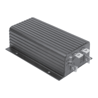
1205 electronic motor controller. Model 1204 has identical connections. Like all Curtis PMC 1200 series controllers, the 1204/1205 models offer superior operator control of the vehicle’s motor drive speed. Key features of the 1204/1205 controllers include: Infinitely variable drive and brake control Power MOSFET design provides high efficiency (for reduced motor... -
Page 8: Fig
Tin-plated solid copper bus bars Push-on connectors for control wiring Familiarity with your Curtis PMC controller will help you to install and operate it properly. We encourage you to read this manual carefully. If you have questions, please contact the Curtis office nearest you. -
Page 9: Hardware Installation
22 × 19 × 3 (0.85 × 0.75 × 0.125) 6 (0.25) male push-on, 3 plcs 133 (5.25) 1204: 174 (6.85) MODEL 1205: 225 (8.85) MODEL 1204: 19 (0.75) 1205: 44 (1.75) (0.13) Dimensions in millimeters and (inches) Curtis PMC 1204/1205 Manual... -
Page 10: Throttle
≈4400 ohms) will work with the standard throttle input. For other types, contact your Curtis office. If a Curtis PMC potbox is used, it must be mounted so as to allow connection between the potbox lever arm and the vehicle accelerator linkage. -
Page 11: Mounting Dimensions
WIRING: = throttle input = switch, common is not used with BLACK BLUE GREEN = throttle input = switch, normally open 1204/1205 controllers) WHITE ORANGE Dimensions in millimeters and (inches) Curtis PMC footpedal FP-2. Fig. 4 Curtis PMC 1204/1205 Manual... -
Page 12: Other Hardware
HARDWARE INSTALLATION OTHER HARDWARE The recommended hardware for a typical 1204/1205 controller installa- tion is shown in Figure 5. Contactors should be mounted in a clean, dry location. If such a location is unavailable, a cover should be used to deflect dirt and water splash. -
Page 13: Main Contactor
Albright SW80 or SW180 (available from Curtis). A coil suppression diode, such as a Curtis PMC p/n MP-1 (which is rated at 100 volts, 3 amps), should be used on the contactor coil. -
Page 14: Keyswitch
(typically 10 amps) connected in series with the B+ feed to the control circuitry wiring is recommended. Power Wiring Fuse To protect the power wiring circuit, a fuse appropriate for the controller’s rated current (see Appendix C) is recommended. Curtis PMC 1204/1205 Manual... -
Page 15: Wiring
Failure to use the double-wrench technique could cause undue strain to be placed on the internal connections, and could also result in cracked seals around the bus bars. Curtis PMC 1204/1205 Manual... -
Page 16: Wiring: Series Motors
– Basic wiring configuration, Fig. 6 Curtis PMC 1204/1205 controller. WIRING: SERIES MOTORS Figure 6 is a schematic of the configuration shown in Figure 5. Wired this way, the vehicle will plug brake if the direction is changed with the vehicle moving and the throttle applied. -
Page 17: Forward/Reverse (With Standard Power Wiring)
field winding. Be careful if you are replacing this type of controller. When using the Curtis PMC controller it is essential that the field be reversed and that the armature be connected directly to the controller’s B+ and A2 terminals, because the plug diode inside... -
Page 18: Forward/Reverse (With Alternate Power Wiring)
2×SPDT contactors (see Figures 6 and 7). As previously noted in the section on standard power wiring, when using the Curtis PMC controller it is essential that the field be reversed and that the armature be connected directly to the controller’s B+ and A2 terminals, because the plug diode inside is connected to these terminals. -
Page 19: Mechanical Reversing Switch
field cables by rotating a movable contact bar. The configura- tion shown is typical; many variations are in use. Power wiring Fig. 9 FUSE MAIN for reversing with mechanical forward/reverse PRECHARGE RESISTOR (250 Ω, 5 W) switch arm. – Curtis PMC 1204/1205 Manual... -
Page 20: Throttle Pot
Throttle Pot Wiring Standard potbox wiring If the throttle input to the controller is from a Curtis PMC potbox or footpedal, the wiring is simple: just connect the two wires of the potbox/ footpedal cable to the two push-on terminals of the controller, as shown in Figure 6. -
Page 21: Reduced Speed Operation
Reduced speed Fig. 13 operation (with standard 0–5k Ω pot). FASTER THROTTLE OPTIONAL INPUT SWITCH SPEED REDUCTION RESISTOR APPROX. % OF ORIGINAL TOP SPEED Curtis PMC 1204/1205 Manual... -
Page 22: Electronic Throttle
Electronic Throttle Wiring Curtis PMC’s electronic throttle, ET-XXX, is wired as shown in Figure 14. It requires a controller with the optional 0–5V throttle input. Curtis electronic Fig. -
Page 23: Wiring: Permanent Magnet Motors
The faster the vehicle is moving when the motor is shorted out, the more CONTROL WIRING PEDAL KEYSWITCH INTERLOCKS FUSE MICROSWITCH POLARITY PROTECTION DIODE POWER WIRING MAIN FUSE PRECHARGE RESISTOR (250 Ω, 5 W) POTBOX – Basic wiring for use with PM motors. Fig. 15 Curtis PMC 1204/1205 Manual... - Page 24 2 × SPDT direction controller B+ FREEWHEEL or DB contactors with a third contactor (SPST). A resistor can be added across the third contactor to provide dynamic braking instead of freewheeling. POWER WIRING CONTROL WIRING Curtis PMC 1204/1205 Manual...
- Page 25 NOTE amount of braking desired are factors in determining the appropriate dynamic braking resistor; contact Curtis for guidelines.) The N.O. and N.C. contacts of the forward/reverse contactors must be wired as shown in Figure 17 or this scheme will not work.
-
Page 26: Installation Checkout
field connections. F. If you have HPD, check it next. Turn off the keyswitch and direction switch. Apply the throttle, turn the keyswitch on, and then select a Curtis PMC 1204/1205 Manual... - Page 27 The vehicle should smoothly brake to a stop and accelerate in reverse. On vehicles that are intended to have plug braking inhibited, verify that the maneuver in “H” produces freewheel coasting. Curtis PMC 1204/1205 Manual...
-
Page 28: Maintenance And Adjustment
MAINTENANCE & ADJUSTMENT MAINTENANCE & ADJUSTMENT Curtis 1204/1205 controllers and potboxes require only minimal main- tenance if properly installed. : The controllers are sealed and thus NOTE are not field serviceable. CONTROLLER Maintenance It is recommended that the following two steps be performed occasion- ally. -
Page 29: Fig. 18 Adjustment Pots
1. Remove the socket head screw (1/8" Allen) for the adjustment you want to make. 2. Adjust the internal potentiometer using a small insulated screw- driver (available from Curtis). 3. Replace the socket head screw and nylon seal washer. To pre- vent stripping, do not over-tighten. Curtis PMC 1204/1205 Manual... -
Page 30: Potbox
(with a moist rag) as required. Adjustment Curtis PMC potboxes are factory set and rarely require user attention. To test and adjust, connect an ohmmeter to the potbox wires and use this procedure: 1. -
Page 31: Troubleshooting And Bench Testing
Sluggish Vehicle Behavior Loss of power will be noticeable when the batteries become overly discharged. This is a normal response to low battery voltage. Curtis PMC 1204/1205 controllers are designed to protect against damage caused by low batteries. On 24–36 volt controllers, for example, power to the motor is cut back when the voltage goes below 16 volts. -
Page 32: In-Vehicle Diagnostic Tests
Hot Controller If the controller gets hot, it does not necessarily indicate a serious problem. Curtis PMC 1204/1205 controllers protect themselves by reducing power to the motor if their internal temperature exceeds 75°C (167°F). Power output will be reduced for as long as the overheat condition remains, and full power will return when the unit cools. -
Page 33: Fig. 19 Guide To Troubleshooting Procedures
Check current in controller’s M- (motor field) lead while circuit. If current is high but depressing pedal. 4-D, E motor won’t turn, check motor, if NO Current should be high, and motor should turn. wiring & plug diode. 4-F, G, H, I Curtis PMC 1204/1205 Manual... - Page 34 If the contactor and KSI terminal are not getting voltage, that’s the problem. Use the voltmeter to find out where it is not getting through. Connect the voltmeter (-) to the controller’s B- terminal and check the following points with the voltmeter (+) lead to trace Curtis PMC 1204/1205 Manual...
- Page 35 5kΩ pot connected as a two- wire rheostat (0 = full off, 5 kΩ = full on), and also to 5kΩ–0 configura- tions. Some 1204/1205 controllers are sold with other input characteris- tics. If your installation uses a controller with a throttle input other than 0–5kΩ...
- Page 36 If the voltages are still out of range, the controller is at fault and should be replaced. Curtis PMC 1204/1205 Manual...
- Page 37 Test the plug diode as follows: 1. Remove power by opening the battery circuit. Take the cable off the controller’s A2 terminal. Curtis PMC 1204/1205 Manual...
-
Page 38: Bench Testing
2. an ACCELERATOR POTBOX. For controllers with the standard input configuration (a 5 kΩ pot wired as a two-terminal rheostat), a Curtis PMC potbox or any 5 kΩ pot will work fine. Curtis PMC 1204/1205 Manual... -
Page 39: Fig. 20 Setup For Bench Testing
Setup for bench testing. Fig. 20 MAIN POWER KEYSWITCH CONTACTOR SWITCH 12 V POWER SUPPLY 12 V (to match your controller) 12 V POTBOX (to match your controller’s throttle input) TEST LOAD (to match battery voltage) Curtis PMC 1204/1205 Manual... - Page 40 The lamps should smoothly increase in brightness to their previous level. F. Finally, remove the controller from the test setup and check its in- ternal plug diode, as described in Troubleshooting Procedure Curtis PMC 1204/1205 Manual...
-
Page 41: Glossary: Features And Functions
This feature contributes to smooth, gentle starts. On some 1204/1205 models, the acceleration rate is adjustable via an externally accessible trimpot. See Section 4 for adjustment instructions. The deceleration rate is fixed, and cannot be adjusted. - Page 42 Curtis PMC controllers dramatically greater driving range per battery charge. Environmental protection Curtis PMC 1204 and 1205 controllers are housed in rugged anodized aluminum extrusions that provide environmental protection. Controllers must be kept clean and dry, however, to ensure long life.
- Page 43 The plug current limit is factory set to meet customer requirements. On some 1204/1205 models, the plug current limit is adjustable via an externally accessible trimpot. See Section 4 for adjustment instructions. If plug braking is not desired, the vehicle can be wired so that moving the forward/reverse switch through neutral causes the vehicle to freewheel as long as the accelerator is applied.
- Page 44 (Appendix C). Reducing the output to the motor allows the battery voltage to recover, and an equilibrium is established in which the battery supplies as much current as it can without falling below the cutback voltage. Curtis PMC 1204/1205 Manual...
-
Page 45: Fig . A-1 Block Diagram, Curtis Pmc 1204/1205 Controller
PLUG CURRENT CURRENT LIMIT ADJUST ADJUST (internal) Block diagram, Curtis PMC 1204/1205 controllers. Fig. A-1 The controllers consist of a and a POWER SECTION LOGIC SECTION POWER SECTION An array of paralleled power metal oxide semiconductor field effect transistors (MOSFETs) switches pulses of current from the battery to the motor. - Page 46 Current limiting is done by sensing the voltage drop across the main power MOSFET switch when it is on. This voltage is compared (current limit comparators) with a current limit reference; when it exceeds the reference, an overcurrent signal acts on the limit integrator to reduce the controller Curtis PMC 1204/1205 Manual...
- Page 47 When the motor has come to a stop, the plug diode will again become reverse biased and the controller will revert to normal drive operation. Curtis PMC 1204/1205 Manual...
-
Page 48: Pulse Width Modulation
Average current, which determines motor torque, is controlled by the ratio of on/off times. Smooth, stepless control of the power delivered to the motor is achieved with almost no power loss in the control components. Curtis PMC 1204/1205 Manual... - Page 49 PWM OPERATING FREQUENCY 15 kHz STANDBY CURRENT less than 20 mA 5 kΩ ±10% (others available) STANDARD THROTTLE INPUT WEIGHT 1204: 1.8 kg (4 lbs) 1205: 2.7 kg (6 lbs) DIMENSIONS 1204: 146mm×170mm×70mm (5.75"×6.75"×2.8") 1205: 146mm×222mm×70mm (5.75"×8.75"×2.8") NOMINAL VOLTAGE UNDER-...
Need help?
Do you have a question about the 1204 and is the answer not in the manual?
Questions and answers