
Related Manuals for Glow-worm SS 115


Summary of Contents for Glow-worm SS 115
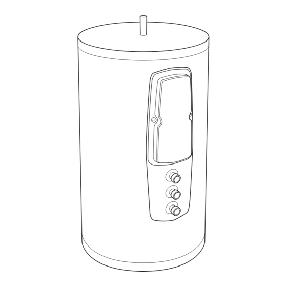
- Page 1 SS 115-SS 150-SS 175-SS 200 SS 250-SS 300 Instructions for Use Installation and Servicing Unvented hot water storage cylinders www.glow-worm.co.uk...
- Page 2 Guarantee Registration Thank you for installing a new Glow-worm cylinder in your home. Glow-worm appliances' are manufactured to the very highest standard so we are pleased to offer our customers' a Comprehensive Guarantee. We recommend you complete and return your Guarantee Registration Card as soon as possible.
-
Page 3: Table Of Contents
Contents The instructions consist of three parts, User, Installation and Servicing Instructions. The instructions are an integral part of the appliance and must, to comply with the current issue of the Gas Safety (Installation and Use) Regulations, be handed to the user on completion of the installation. -
Page 4: Testing And Certification
UK standard boilers in hot water supply systems. Applications Glow-worm cylinders are available in six sizes; 115, 150, 175, 200, 250 and 300 litre. The Glow-worm cylinder can be connected to any UK The cylinders are of stainless steel construction, insulated standard boiler. -
Page 5: Technical Data
1 Technical Data SS 300 SS 250 SS 200 SS 175 SS 150 SS 115 SS 115 SS 150 SS 175 SS 200 SS 250 SS 300 Unit Size litres Nominal DHW flow from GW 115/150/175/200 15 l/min @ 60°C GW 250/300 20 l/min @ 60°C... -
Page 6: Instructions For Use
It is important that your hot water cylinder is serviced annually N OTE: If the Glow-worm cylinder is installed in a cupboard by a competent person approved at the time by the Health used for airing purposes please ensure that clothing or and safety Executive. - Page 7 2 Instructions for Use 2.6 Guarantee Glow-worm offers a guarantee of 25 years for the stainless steel vessel against faulty materials or manufacture: The following information is important as without it your guarantee may be invalid. 1. The warranty will become invalid if the damage is due to scaling, frost damage, transient voltages, lightning strikes or any act of vandalism or misuse.
-
Page 8: Note To Installer
40°C will be 25 l/min temperature control under the front panel. (from 15 l/min hot water from the Glow-worm cylinder @ 60 °C 5. Suitable clearances exist to allow installation, checking and together with 10 l/min cold water @ 10°C). -
Page 9: Installation
It must be positioned away from any electrical components and installed in the same space as the Glow-worm cylinder, so that it is visible to the user. The D1 discharge pipe from the T&S Valve/Expansion Valve Typical discharge pipe arrangement Diagram 4.1... - Page 10 The discharge pipe from the pressure relief valve of the boiler 3. The likelihood of a pram being left beneath the point of may be tee'd into the discharge pipework from the Glow-worm discharge. downstream of the tundish in the horizontal pipework.
- Page 11 4 Installation FUNCTIONAL DIAGRAM Diagram 4.4 Diagram 4.5 FUNCTIONAL DIAGRAM...
-
Page 12: Installation Procedure
Never cap or block the outlet of the expansion relief valve. Activate the expansion relief valve regularly to prevent from calcification. Provide a cold water mains supply to the Glow-worm cylinder. To ensure optimum performance from the Glow-worm cylinder, and particularly in installations where the balanced pressure cold water outlet (5, diagram 4.7) is to be used, the... - Page 13 IMPORTANT: The immersion heater incorporates an energy terminals of the wiring centre. cut-off device and must not under any circumstances be Connect the Glow-worm cylinder controls and the 2 port valve replaced by a standard immersion heater. flying lead to the terminals of the wiring centre.
- Page 14 4 Installation Control options – system wiring scheme Main Supply Boiler Terminal 2 Channel Programmer 3 Amp Fused External wiring box (Do not use pre-wired printed circuit board type) Pump not used BL BR GR OR BL BR GR OR L in L out Cylinder Stat...
- Page 15 Open all the hot and cold water outlet taps or other fittings. Carry out the commissioning and testing procedures Open the mains water supply to the Glow-worm cylinder and detailed in the installation instructions supplied with the continue filling until water runs freely from the outlet taps/ boiler.
- Page 16 7 Fault Finding Diagram 7.1 FAULT A...
- Page 17 7 Fault Finding FAULT B Diagram 7.2...
- Page 18 7 Fault Finding FAULT C Diagram 7.3...
- Page 19 7 Fault Finding FAULT D Diagram 7.4...
- Page 22 COMMISSIONING CHECKLIST MAINS PRESSURE HOT WATER STORAGE SYSTEM...
- Page 23 SERVICE INTERVAL RECORD It is recommended that your heating system is serviced regularly and that you complete the appropriate Service Interval Record Below . Service Provider. Before completing the appropriate Service Interval Record below, please ensure you have carried out the service as described in the boiler manufacturer’s instructions.
- Page 24 Because of our constant endeavour for improvement, details may vary slightly from those shown in these instructions. 0020005469_01 Glow-worm, Nottingham Road, Belper, Derbyshire. DE56 1JT www.high-efficiency.info...
Need help?
Do you have a question about the SS 115 and is the answer not in the manual?
Questions and answers