Table of Contents
Advertisement
3515H_Manuals 6/2/10 9:00 AM Page 1
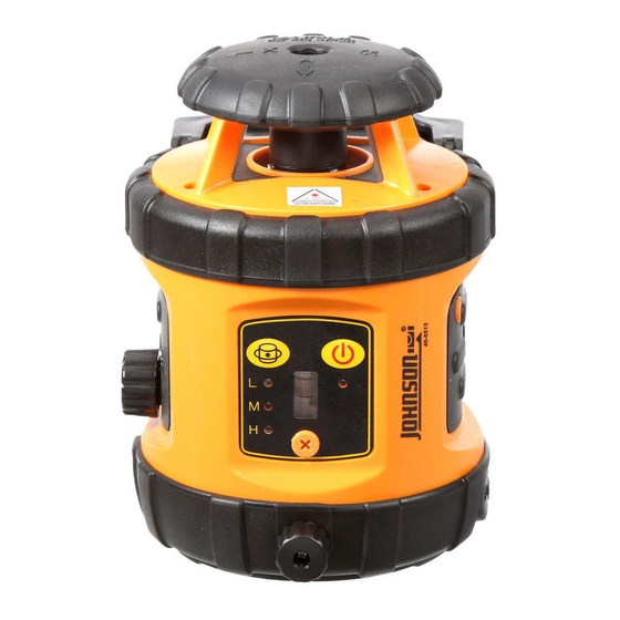
Self-Leveling Rotary Laser Level
Model Nos. 40-6515, 40-6516 and 40-6517
Instruction Manual
Congratulations on your choice of this Self-Leveling Rotary Laser
Level. We suggest you read this instruction manual thoroughly before
using the instrument. Save this instruction manual for future use.
This is a Class IIIa laser tool and is manufactured to comply
with CFR 21, parts 1040.10 and 1040.11 as well as international
safety rule IEC 285.
©2010 Johnson Level & Tool - Rev. 1
1
Advertisement
Table of Contents

Related Manuals for Johnson 40-6515


Summary of Contents for Johnson 40-6515
- Page 1 Save this instruction manual for future use. This is a Class IIIa laser tool and is manufactured to comply with CFR 21, parts 1040.10 and 1040.11 as well as international safety rule IEC 285. ©2010 Johnson Level & Tool - Rev. 1...
-
Page 2: Table Of Contents
Self- Leveling Rotary Laser Level “AA” Alkaline Batteries Tinted Glasses Detector with “AAA” Batteries and Clamp Magnetic Target Elevating Tripod Wall/Ceiling Mount 8’ Grade Rod Instruction Manual with Warranty Card Hard Shell Carrying Case ©2010 Johnson Level & Tool - Rev. 1... -
Page 3: Features And Functions
Please read and understand all of the following instructions, prior to using this tool. DANGER! Class IIIa Laser Product Max. Power Output: Wavelength: 625-645nm THIS TOOL EMITS LASER RADIATION. DO NOT STARE INTO BEAM. AVOID DIRECT EYE EXPOSURE. ©2010 Johnson Level & Tool - Rev. 1... - Page 4 • Use only original Johnson ® parts and accessories purchased from your Johnson ® authorized dealer. Use of non-Johnson ® parts and accessories will void warranty. ©2010 Johnson Level & Tool - Rev. 1...
-
Page 5: Location/Content
3515H_Manuals 6/2/10 9:00 AM Page 5 4. Location/Content of Warning Labels ©2010 Johnson Level & Tool - Rev. 1... -
Page 6: Location Of Parts/Components
Battery Door Rotating Laser Output Widow Keypad Lock Knob – Compensator/ Transportation Vertical Vial Vertical Vial Adjustment Knob DC 6V Outlet (6V Adapter not included) 5/8” – 11 Screw Charging LED Thread ©2010 Johnson Level & Tool - Rev. 1... -
Page 7: Operating Instructions
Bubble Adjustment While in Use Vertically 1. Turn the lock knob counter-clockwise to off position to “LOCK” the compensator. The laser is now operating in a “manual mode” and is not self-leveling. ©2010 Johnson Level & Tool - Rev. 1... -
Page 8: Using The Product
“On” position. Power Key: Press this key to power on/off the laser. Power LED: Lighted LED mean power-on Extinguished LED means power-off Flashing LED means weak battery voltage ©2010 Johnson Level & Tool - Rev. 1... - Page 9 Set the lock knob to the on position. Power on. During the process of self-leveling, if the laser is tilted to exceed its self-leveling range, it will stop rotating and will give a sound alarm. ©2010 Johnson Level & Tool - Rev. 1...
- Page 10 3. Power on the laser and select your desired speed by pressing the keys on the keypad. 4. After operations or before moving the unit, please power off and lock the laser first. ©2010 Johnson Level & Tool - Rev. 1...
- Page 11 6. Coarse/Fine detection button 7. Power button 8. Threaded hole 9. Battery-box cap (b) Display 1. Power symbol 2. Low battery symbol 3. Coarse/Fine detection symbol 4. Sound symbol 5. Detecting position symbol ©2010 Johnson Level & Tool - Rev. 1...
- Page 12 2. screw • Position the detector on the clamp holder using the screw of the clamp holder. • Position the clamp holder on rod using the clamp bolt of the clamp holder. ©2010 Johnson Level & Tool - Rev. 1...
- Page 13 3515H_Manuals 6/2/10 9:00 AM Page 13 (d) Detection 1. Coarse detection • Aim the receiving window at the rotating laser. Loosen the clamp bolt and move the detector up and down to receive the laser scanning signals transmitted by the rotating laser. •...
- Page 14 If the detector comes into contact with water or other liquids, wipe it dry immediately. • Do not use detector around fire or expose it to fire in any way. ©2010 Johnson Level & Tool - Rev. 1...
- Page 15 Sound function Short sound and solid sound LED indication Upper red, middle orange, middle green, down red Size 4.645” x 2.637” x 0.984” (118mm x 67mm x 25mm) Weight 0.253 lbs. (115g) ©2010 Johnson Level & Tool - Rev. 1...
- Page 16 When turning the power on and the down signal indicator flashes, it means that the battery is low and it is necessary to replace the battery. Power Key: Turn on/off the detector ©2010 Johnson Level & Tool - Rev. 1...
-
Page 17: Battery Installation
The laser beam is No laser down to center exactly to center beam is detected Sound: Single short Sound: Single short Sound: Single short Sound: Solid sound Sound: sound sound sound No Sound ©2010 Johnson Level & Tool - Rev. 1... - Page 18 6 minutes, the middle signal indicator will turn green first and then turn red. The horn will give two short sounds and the detector will power off automatically. ©2010 Johnson Level & Tool - Rev. 1...
- Page 19 3515H_Manuals 6/2/10 9:00 AM Page 19 5. Accessories Usage • Connecting to the grade rod bracket • Connecting to the grade rod ©2010 Johnson Level & Tool - Rev. 1...
- Page 20 If detector comes into contact with water or other liquids, wipe it dry immediately. • Do not use detector around fire or expose it to fire in any way. ©2010 Johnson Level & Tool - Rev. 1...
- Page 21 4. Turn the laser by 180 degrees, mark the beam as point B. 5. Measure the vertical distance between point A and point B. If A & B are more than 1/16” apart at 25’, the laser is out of calibration. 25’ ©2010 Johnson Level & Tool - Rev. 1...
- Page 22 3. After X is calibrated, rotate the instrument 90º to calibrate the Y- direction. Note: The alkaline batteries must be removed to access the instrument core with a flat head screwdriver. 4. Reinstall the adjustment-hole bolt. ©2010 Johnson Level & Tool - Rev. 1...
- Page 23 2. Insert the Allen wrench into the adjustment hole to adjust the Allen screw. 3. Rotate the Allen wrench to center the bubble. 4. After adjustment operation, please install the bubble-adjustment- hole bolt back to its original position. ©2010 Johnson Level & Tool - Rev. 1...
-
Page 24: Technical Specifications
3515H_Manuals 6/2/10 9:00 AM Page 24 Screw off the self-calibration-hole bolt Calibrate the bubble Note: If you fail to calibrate the accuracy according to the above steps, please contact Johnson Level & Tool for service. 9. Technical Specifications Laser Wavelength 635nm±10nm... -
Page 25: Application Demonstrations
3515H_Manuals 6/2/10 9:00 AM Page 25 10. Application Demonstrations Ceiling installation Wall or footing construction Squaring and leveling Baseboard installation Fence installation Cement floor installation Window installation Anti-static flooring installation ©2010 Johnson Level & Tool - Rev. 1... -
Page 26: Care And Handling
12. Product Warranty Johnson Level & Tool offers a three year limited warranty on each of its products. You can obtain a copy of the limited warranty for a Johnson Level & Tool product by contacting Johnson Level & Tool's Customer Service Department, as provided below, or by visiting our web site at www.johnsonlevel.com. -
Page 27: Warranty Registration
For further assistance, or if you experience problems with this product that are not addressed in this instruction manual, please contact our Customer Service Dept. In the U.S., contact Johnson Level & Tool’s Customer Service Department at 888-9-LEVELS. In Canada, contact Johnson Level & Tool’s Customer Service Department at 800-346-6682. -
Page 28: Accessories
NO WARRANTY. If you need any assistance in locating any accessories, please contact our Customer Service Department. In the U.S., contact Johnson Level & Tool’s Customer Service Department at 888-9-LEVELS. In Canada, contact Johnson Level & Tool’s Customer Service Department at 800-346-6682.
Need help?
Do you have a question about the 40-6515 and is the answer not in the manual?
Questions and answers