Macurco CM-6 User Instructions
Carbon monoxide detector, controller and transducer
Hide thumbs
Also See for CM-6:
- User instructions (72 pages) ,
- Application manual (16 pages) ,
- User instructions (43 pages)

Related Manuals for Macurco CM-6


Summary of Contents for Macurco CM-6
- Page 1 Macurco™ Carbon Monoxide Detector, Controller and Transducer CM-6 User Instructions Important: Keep these User Instructions for reference...
-
Page 2: Table Of Contents
Fan Relay setting Fan Relay Delay setting Fan Minimum Runtime setting 4-20mA Output setting On Board Diagnostics Sensor Poisons MAINTENANCE Cleaning Testing Operation Test Carbon Monoxide Gas Test Aerosol Carbon Monoxide Test Field Calibration Procedure MACURCO GAS DETECTION PRODUCTS WARRANTY... -
Page 3: General Safety Information
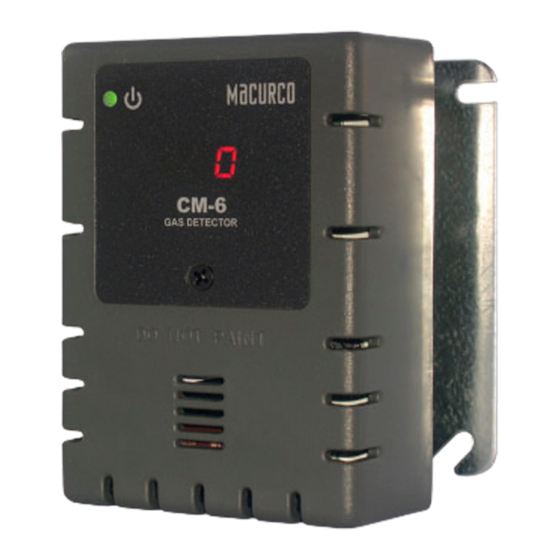
CO concentrations in parking garages, maintenance facilities or other commercial applications. The CM-6 is a low level meter capable of displaying from 0-200 ppm (parts per million) of Carbon monoxide. The CM-6 is factory calibrated and 100% tested for proper operation, but can also be calibrated in the field. -
Page 4: Use Instructions And Limitations
Do not mount the CM-6 where the normal ambient temperature is below 0°F or exceeds 125°F (- 18C or above 52C). The CM-6 mounts on a type 4S electrical box supplied by the contractor. Do not install the CM-6 inside another box unless it has good air flow through it. -
Page 5: Specifications
Location A CM-6 is normally mounted at breathing level, about 5 feet (1.5 meters) above the floor on a wall or column in a central area where air movement is generally good. The unit, on average, can cover about 5,000 sq. ft. (465 sq. -
Page 6: Installation
Installation 1. The CM-6 mounts on a 4” square (or 4x4) electrical box supplied by the contractor. Do not mount the CM-6 inside another box, unless it has good air flow through it. 2. Connect the CM-6 to Class 2 power supply only. It is suggested to use a separate transformer for powering the unit or units because of possible interference’s from other devices on the same power supply. -
Page 8: Power Up
Power Up The CM-6 steps through an internal self-test cycle for the first 1 minute that it is powered. The unit will execute the test cycle any time power is dropped and reapplied (i.e. power failure). During the self-test cycle the unit will display the Firmware Version number, then count down from 60 to 0 and finally go into normal operation. -
Page 9: Operation
The default Fan Relay Runtime setting is OFF The default 4-20mA Output setting is OFF To change settings, remove the Philips screw on the front of the CM-6. Pull off the front cover of the unit. Selecting Default Configuration – “dEF”... -
Page 10: Alarm Relay Configuration
the second selection “PUt” or Power Up Test setting. Push Enter. If the testis “On” push Next to turn it “OFF” (flashing) then push Enter to confirm the change (solid) and push Enter again to return to “PUt” in the Con menu. -
Page 11: Onboard Diagnostics
(such as hydrogen sulfide, sulfur dioxide) for an extended period of time. MAINTENANCE The CM-6 does not require regular maintenance. The unit uses a long life electrochemical sensor that has a 7 year life expectancy (in normal conditions). All maintenance and repair of products manufactured by Macurco... -
Page 12: Cleaning
Operation Test Normally this will be the only test required for the CM-6 and is the recommended way to test the unit or units after installation. Check that the green CM-6 operating LED light is illuminated continuously. If not, do not proceed with the tests. -
Page 13: Carbon Monoxide Gas Test
(CO) in air Gas regulator with about two feet of plastic tubing Humidifier CM-6-CH calibration hood FCK Information Several detectors can be calibrated with one FCK. The only limitation is the amount of gas in the cylinder. The 17 liter cylinder has approximately 85 minutes of continuous calibration run time. - Page 14 5. Turn on the regulator to start the gas flow and wait with the gas applied continuously. 6. With the display function turned “On”, the CM-6 will show the current concentration of CO or “0” (zero) in clean air. When the CO concentration reaches the Fan Relay setting (35 ppm, for example) the display will flash back and forth between “FAn”...
-
Page 15: Aerosol Carbon Monoxide Test
4. The display option should be set to “On” and reading 0 ppm in clean air. 5. With the CM-6 cover on, aim the nozzle of the aerosol can into the sensor grate area (under DO NOT PAINT) and press for 2 to 3 seconds. -
Page 16: Field Calibration Procedure
Note: For optimum calibration results the unit should be in clean air and be in a low ambient air flow. 1. Remove the Philips screw on the front of the CM-6. Pull the front cover of the unit off. 2. Assemble the 200 ppm gas cylinder and regulator together.
Need help?
Do you have a question about the CM-6 and is the answer not in the manual?
Questions and answers