Table of Contents
Advertisement
Advertisement
Table of Contents

Related Manuals for Invacare Mistral


Summary of Contents for Invacare Mistral
- Page 1 Invacare® Mistral Power Wheelchair Operating Instructions...
- Page 2 How can you get in touch with Invacare®? If you have any questions or need support, please contact your authorised Invacare® Dealer first. He has the necessary know-how and equipment plus the special knowledge concerning your Invacare® product which enables him to offer you all-round satisfactory service. Should you wish to contact us directly, you can reach us in Europe at the following addresses and phone numbers.
- Page 3 +31 - (0) 318 - 69 57 57 Fax (Kundeservice): +47 - 22 57 95 01 Fax: +31 - (0) 318 - 69 57 58 INVACARE® PORTUGAL Lda INVACARE® AB Rua Senhora de Campanhã, 105 Fagerstagatan 9 4369-001 Porto 163 91 Spånga...
-
Page 4: Table Of Contents
Table of Contents Chapter Page Introduction ..................7 Important symbols in this manual ..................9 Type Classification and Area of Use ..................9 Safety Notes...................10 General Safety Notes ......................10 Safety Information on Electromagnetic Interference ............13 Safety Information on Driving and Freewheel Mode ............14 The most important parts .............16 Getting in and out of the wheelchair ...........17 Removing / inserting armrest....................17... - Page 5 7.1.3 Activating and deactivating the Interlock .................25 Controlling the wheelchair with the Joystick Box..............26 7.2.1 How the wheelchair reacts to Joystick movements............27 7.2.2 Error Codes ........................28 Seating systems ................30 Standard Seat........................30 8.1.1 Adjusting Seat Angle .......................30 8.1.2 Adjustment of the back inclination by means of a punched plate (optional) ....31 Armrests / side parts......................32 8.2.1 Adjusting height of armrest ....................32...
- Page 6 Care and maintenance ..............47 Repair Instructions................50 12.1 Repairing a flat tyre......................50 Transport..................52 13.1 Removing Legrests......................52 13.2 Removal of the kerb climber .....................53 13.3 Removing the Batteries ....................54 13.4 Removing Battery Box ......................56 13.5 Removing the Headrest ....................57 13.6 Loosening the backrest cross-bar ..................58 13.7 Folding the Wheelchair .....................59 13.8...
-
Page 7: Introduction
Invacare® and its legal representatives assume no liability in cases where a wheelchair is not suitable for a particular user. - Page 8 Some of the required maintenance jobs or adjustments can be performed by the user or by an attendant. Certain adjustments, however, require technical training and may only be performed by your specialised Invacare® dealer. Any damage or errors resulting from not complying with the operating instructions, or due to incorrect maintenance are excluded from the warranty.
-
Page 9: Important Symbols In This Manual
Important symbols in this manual WARNING: This symbol warns you of danger! • Follow the instructions to avoid injury to the user or damage to the product! NOTE: This symbol indicates hints and suggestions which should help make operating the product easier and point out special functions. -
Page 10: Safety Notes
Safety Notes • READ WELL BEFORE OPERATION! General Safety Notes Danger of injury if wheelchair is used in any other way than the purpose described in this manual! • Adhere strictly to the instructions in this User's Manual! Danger of injury if the wheelchair is driven when ability to operate a vehicle is impaired by medication or alcohol! •... - Page 11 Danger of injury if the On/Off Button is pressed while the wheelchair is in motion, due to it coming to an abrupt, sharp stop! • If you have to brake in an emergency, simply release the joystick which will bring you to a halt! Danger of injury when transferring wheelchair to another vehicle for transport with the occupant seated in it!
- Page 12 Danger of fire or breaking down due to electric devices being connected! • Do not connect any electric devices to your wheelchair that are not expressly certified by INVACARE® for this purpose! Have all electrical installations done by your authorised INVACARE® Dealer!
-
Page 13: Safety Information On Electromagnetic Interference
Safety Information on Electromagnetic Interference This electric vehicle was successfully tested in accordance with international standards as to its compliance with Electromagnetic Interference (EMI) Regulations. However, electromagnetic fields, such as those generated by radio and television transmitters, and cellular phones, can influence the functions of electric vehicles. -
Page 14: Safety Information On Driving And Freewheel Mode
Safety Information on Driving and Freewheel Mode Danger of injury if the wheelchair tips over! • Only ever negotiate gradients of up to the maximum defined in the Technical Specifications and only with the backrest and seat tilt in an upright position! •... - Page 15 Danger of breaking down in adverse weather conditions, i.e. extreme cold, in an isolated area! • If you are a user with severely limited mobility, we advise that in the case of adverse weather conditions DO NOT attempt a journey without an accompanying attendant! Danger of injury if your foot slides off the footrest and gets caught underneath the wheelchair when it is in motion! •...
-
Page 16: The Most Important Parts
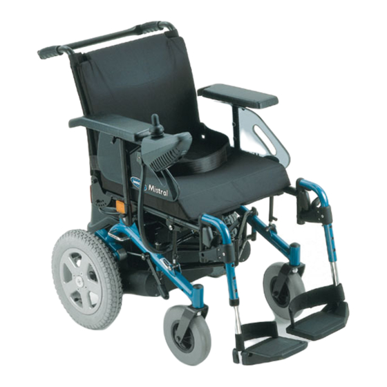
The most important parts 1. Push handle 2. Backrest 3. Armrest 4. Joystick box 5. Footrests 6. Disengagement lever 7. Drive motor 8. Battery box 9. Crossbar... -
Page 17: Getting In And Out Of The Wheelchair
Getting in and out of the wheelchair Removing / inserting armrest To get in and out from the side, the armrest must be removed. To remove: Insert/Remove • Side Part Loosen clamping lever (1). • Pull side part (2) out of its receptacle. To insert: •... - Page 18 Getting into the wheelchair: • Position your wheelchair as close as possible to your seat. This might have to be done by an attendant. • Switch your wheelchair off. • Apply the hand brake of your wheelchair (if existing). • Detach the side part of your wheelchair or swivel it up.
-
Page 19: Driving
Driving Before driving for the first time... Before you take your first trip, you should familiarise yourself well with the operation of the vehicle and with all operating elements. Take your time to test all functions and driving modes. NOTE: If installed, use the restraining systems (seat belts) each time you use the vehicle. -
Page 20: Taking Obstacles
Taking Obstacles Your Invacare® Mistral can climb kerbs and other obstacles of the following heights. • Invacare® Mistral without kerb climber ..4 cm • Invacare® Mistral with kerb climber ....8 cm CAUTION: Danger of Tipping Over! • Never approach obstacles at an angle! •... -
Page 21: Driving Up And Down Gradients
Driving up and down gradients The Invacare® Mistral has a safe climbing ability of 17%. When travelling uphill or downhill, you should by all means observe the following warnings: WARNING: Danger of tipping over! • Only ever drive downhill at a maximum of 2/3 of the top speed! •... -
Page 22: Pushing The Wheelchair By Hand
Pushing the wheelchair by hand The motors of the wheelchair are equipped with automatic brakes, preventing that the wheelchair starts rolling out of control when the joystick box is switched off. When pushing the wheelchair, the magnetic brakes must be disengaged. Disengaging Motors Danger of the vehicle running away! •... -
Page 23: The Joystick Box
The Joystick Box Components and controls on the Joystick Box Bottom 1. Battery charge display 2. ON/OFF-Button 3. ON/OFF-LED / Status Display 4. REDUCE SPEED Button 5. Joystick 6. Interlock (key symbol) 7. INCREASE SPEED Button 8. Driving Speed Display 9. -
Page 24: Status Display
7.1.1 Status Display The ON/OFF LED also serves as an Error Code Display (Status Display). For more information on Error Codes see chap. "Error Codes" on page 28. 7.1.2 Battery Charge Display All LED's are lit: Yellow and red LED's are lit: Only red LED's are still lit and / or flashing: Full range... -
Page 25: Activating And Deactivating The Interlock
Activating and deactivating the Interlock • Interlock Touch the Interlock Key Symbol on the Joystick Box with the end of the magnetic key, which has the Invacare® logo on it. The horn beeps once. The Interlock is activated / deactivated. Magnetic key... -
Page 26: Controlling The Wheelchair With The Joystick Box
Gently move the Joystick in the desired direction (see chapter "How the wheelchair reacts to Joystick" on page 27). NOTE: The electronic system is programmed at the factory with standard values. Your Invacare® Dealer can individually re-program your wheelchair to better suit your particular needs. -
Page 27: How The Wheelchair Reacts To Joystick Movements
7.2.1 How the wheelchair reacts to Joystick movements Direction of travel for wheelchairs The farther the Joystick is moved in any direction, with rear-wheel drive. the more dynamically the wheelchair reacts. NOTE: To brake quickly, just let go of the Joystick. It automatically returns to a neutral position, causing the wheelchair to brake. -
Page 28: Error Codes
7.2.2 Error Codes The electronic system is able to detect and correct some faults automatically. If successful, the Status Display will quit flashing. To perform this test, turn the Joystick Box OFF, wait 5 seconds, and then turn it back ON again. Repeat this procedure a few times, if necessary. If the problem persists, proceed to localise the source of the problem using the following Error Codes: Error Codes: Flash Code:... - Page 29 Flash Code: Meaning: First Aid: What to do if the problem persists: • • General fault / brake fault 5 Flashes Check connectors. Contact dealership on right motor. Connection loose or faulty. • Motors disengaged Engage motors. Switch Joystick OFF and then back ON again.
-
Page 30: Seating Systems
Seating systems Standard Seat 8.1.1 Adjusting Seat Angle • Adjusting Seat Frame Loosen both Allen screws (1) at the stay rods. • Adjust seat angle by lifting and lowering the seat frame. • Tighten again both Allen screws (1). Danger of injury by stay bars that are not duly fixed. The seat angle can become maladjusted automatically under the effect of jerks caused by abrupt braking or driving movements! •... -
Page 31: Adjustment Of The Back Inclination By Means Of A Punched Plate (Optional)
8.1.2 Adjustment of the back inclination by means of a punched plate (optional) The inclination of the backrest is adjusted by means of the borehole plates, Position of the Borehole which are attached to the backrest. Plate The inclination is adjusted by selecting different pairs of holes, allowing for adjustment angles between 0°... -
Page 32: Armrests / Side Parts
Armrests / side parts 8.2.1 Adjusting height of armrest • Adjustment of Armrest Loosen wing screw (1). Height • Push armrest to the desired height. • Retighten the wing screw. 8.2.2 Adjusting width of side parts • Loosen clamping lever (1). •... -
Page 33: Adjusting Headrest
Adjusting Headrest 8.3.1 Adjusting Height of Headrest • Height Adjustment Loosen clamping lever (1). • Push headrest to the desired height. • Tighten clamping lever. 8.3.2 Adjusting Headrest Angle • Loosen clamping lever (2). Adjustment of Position • Swivel headrest into the desired position. •... -
Page 34: Footrests And Legrests
Footrests and Legrests "Standard 80" Footrest 9.1.1 General The angle (80°) of the footrest in relation to the seating surface is fixed. The "Standard 80" Footrest length of the footrest is adjustable. The adjustment of the footrest is performed with the corresponding tools. -
Page 35: Removing Footrest
9.1.2 Removing Footrest • Unlock footrest by pressing or pulling the catch lever (1). Unlocking Footrest • Swivel footrest outward by approx. 90° (2). • Pull footrest upward from its receptacle. Removing Footrest... -
Page 36: Adjusting Length Of Footrest
9.1.3 Adjusting Length of Footrest Tools: 1x Wrench; 10 mm 1x Allen key; 5 mm • Loosen fastening screw using the 4 mm Allen key and 10 mm wrench, and Adjust length remove. • Adjust footrest to the desired height and align holes. •... -
Page 37: Electrical System
Electrical System 10.1 Electronics Protection System The vehicle's electronics are equipped with an overload-protection system. If the motors are put under considerable strain for a longer period of time (for example, when driving up a steep hill) and especially when the ambient temperature is high, then the electronic system could overheat. -
Page 38: The Main Fuse
The master fuses are either directly mounted to the positive poles of the batteries or to the lower side of the battery lid. They can be replaced only after dismounting the battery lid. NOTE A defective main fuse may be replaced only after checking the entire electric system. An Invacare® specialised dealer must perform the replacement. -
Page 39: Batteries
10.2 Batteries 10.2.1 What you need to know about batteries Power is supplied to the vehicle by two 12V gel batteries. The batteries are maintenance-free and only need regular charging. New batteries should always be once fully charged before their first use. New batteries will be at their full capacity after having run through approx. - Page 40 NOTE: Pay attention to the Battery Charge Indicator! Make sure to charge the batteries when the Battery Charge Indicator shows that battery charge is low. We recommend charging the batteries after each trip, as well as each night over night. Depending on the level of discharge, it can take up to 12 hours until the batteries are fully charged again.
-
Page 41: Charging The Batteries
10.2.2 Charging the batteries • Make sure you read and understand the battery charger's User's Manual, as well as the safety notes on its front and rear panels! WARNING: Danger of explosion and destruction of batteries if the wrong battery charger is used! •... - Page 42 The charging socket is on the bottom of the Joystick Box. Connecting the charger Proceed in the following order: • Connect the battery charger to the Joystick Box. • Connect the battery charger to the mains power supply and switch on. Disconnecting the charger Proceed in the following order: •...
-
Page 43: Removing And Fitting Batteries
10.2.3 Removing and fitting batteries WARNING: Danger of injury if the batteries are not handled correctly during assembly and maintenance work! • Batteries may only be removed and installed by authorised technicians! • Observe the warnings on the batteries! • Take into account the heavy weight of the batteries! •... -
Page 44: Removing The Batteries
10.2.3.1 Removing the batteries Requirements: • Wrench 10 mm • Wrench 13 mm • Wrench 19 mm NOTE The removal of the batteries from the battery box is described in detail in chapter "Removing the Batteries" on page 54. • Open battery carrying strap (1). -
Page 45: Connecting The New Batteries
10.2.3.2 Connecting the New Batteries • Fasten battery clamp (2) of the red cable to the positive pole of the battery and tighten by means of a wrench. • Fasten battery clamp (2) of the blue cable to the negative pole of the battery and fasten by means of a wrench. -
Page 46: How To Handle Damaged Batteries Correctly
Only ever transport damaged batteries in an appropriate acid-resistant receptacle. • Wash all objects that have come into contact with acid with lots of water. Disposing of dead or damaged batteries correctly Dead or damaged batteries can be given back to your dealer or directly to Invacare®. -
Page 47: Care And Maintenance
Care and maintenance NOTE: Have your vehicle checked once a year by an authorised Invacare® dealer in order to maintain it's driving safety and roadworthiness. Cleaning the vehicle When cleaning the vehicle, pay attention to the following points: • Only use a damp cloth and gentle detergent. - Page 48 Maintenance Jobs Seat and backrest padding: - Check for perfect condition. Side part and armrest: - Are all fastening elements installed? - Can armrests / side parts be removed and installed without too much physical effort? - Are armrests secured in their positions? Legrests: - Do legrests lock into place without any problem? - Do the different adjustment functions work without any problem?
- Page 49 If the wheelchair is serviced at regular intervals, damaged or worn parts can be located and replaced in time, thus preserving it in good working order. A complete checklist of necessary maintenance work can be found in the Service Manual, which can be obtained from Invacare®.
-
Page 50: Repair Instructions
Repair Instructions 12.1 Repairing a flat tyre WARNING: Danger of the wheelchair running away! • Engage the motors! • Prevent the wheelchair from rolling away when jacking it up by placing wedges under the wheels! Tools: • Allen key, 5 mm Removing the rear wheel Remove wheel •... - Page 51 Repairing a flat • Remove valve cap. • Let the air out of the tyre by pressing the pin in the centre of the valve. • Remove screws that hold the rim together. • Remove the tyre and the inner tube from the wheel. •...
-
Page 52: Transport
Transport The preparations for transport are to be performed in the following order: • Remove legrests. • Remove kerb climber (available as an option and not always mounted). • Remove the backrest crossbar • Detach all connection cables. • Remove batteries. •... -
Page 53: Removal Of The Kerb Climber
13.2 Removal of the kerb climber The kerb climber is mounted by means of plug-in shafts. The plug-in shafts are equipped with locking balls 1) which prevent that the plug-in shaft slips out of its receptacle. The locking balls are released by pressing down the release button (2). This will make possible the quick attachment and removal of the kerb climber. -
Page 54: Removing The Batteries
13.3 Removing the Batteries Caution! Danger of bruising due to the heavy weight of the battery box! • The battery box should be lifted by two persons only. • Do not reach under the battery box. • Disconnect cable from socket on battery box lid. •... - Page 55 • Remove battery box lid by pulling it towards the rear out of the wheelchair. • Disconnect battery cables from batteries. • Remove batteries from battery box.
-
Page 56: Removing Battery Box
13.4 Removing Battery Box • Unfasten the belt that holds the battery box. • Pull battery box out of the frame. -
Page 57: Removing The Headrest
13.5 Removing the Headrest To remove the headrest: Removing Headrest • Loosen the clamping lever (1). • Pull the headrest from its support (2). -
Page 58: Loosening The Backrest Cross-Bar
13.6 Loosening the backrest cross-bar Loosen the crossbar • Loosen the thumbscrews at both ends of the crossbar (1). • Unhook the crossbar on the right side and swing away. -
Page 59: Folding The Wheelchair
13.7 Folding the Wheelchair Step 1 Step 2 Step 3 • • • Remove seat cushion. Lean wheelchair to one side. Push together. • Pull seat plate up by its front and rear edges. -
Page 60: Unfolding The Wheelchair
13.8 Unfolding the Wheelchair WARNING: Danger of injury! • When pushing the seat down, make sure not to get your fingers caught between the two seat panels! • Pressing Down To unfold, lift the wheelchair slightly from one side and open by pressing Seat Plate apart the backrest handles and the armrests. -
Page 61: Reassembling The Wheelchair
13.9 Reassembling the Wheelchair NOTE: The assembly of the wheelchair is performed in reverse order in relation to the disassembly. CAUTION: Danger of injury if the battery box is not safely locked into place! • After the assembly of the wheelchair, it must be ensured that the retaining bolts that keep the battery case in place, are safely locked! To make sure, shake and pull at the battery box! -
Page 62: Technical Specifications
Technical Specifications Electric System • 31 AH, MU-1SLD G Batteries • 50 AH, M22NF SLD G • 2x 50 A (1x per Battery) Battery master fuse Weight • approx. 64 kg (with 31 Ah batteries) Empty weight • approx. 80 kg (with 50 Ah batteries) •... -
Page 63: Inspections Performed
It is confirmed by stamp and signature that all jobs listed in the inspection schedule of the Service and Repair Instructions have been properly performed. The list of the inspection jobs to be performed can be found in the Service Manual which is available through INVACARE®. Delivery Inspection... - Page 64 Order No. of this Manual: B292003.DOC Release Date: 21.05.01 English...
Need help?
Do you have a question about the Mistral and is the answer not in the manual?
Questions and answers