Advertisement
Quick Links
LED
State
Green
Power
Off
Green flashing
Status
Green
HA
Green
Red
Alarm
Amber
Off
Green
POE
Off
Ready
Green
Link/
Green
Activity
Flashing
Ports 1 to 8
Speed
Off
Amber
Link/
Green
Activity
Flashing
Ports 9 to 16
Speed
Green
Amber
Off
Package Contents
Interface
Type
Console
RJ-45
Ports 1 to 8
RJ-45
Ports 9 to 12
RJ-45
Ports 13 to 16
RJ-45
USB
USB
FSM
FSM
1
3
STATUS
ALARM
READY
2
4
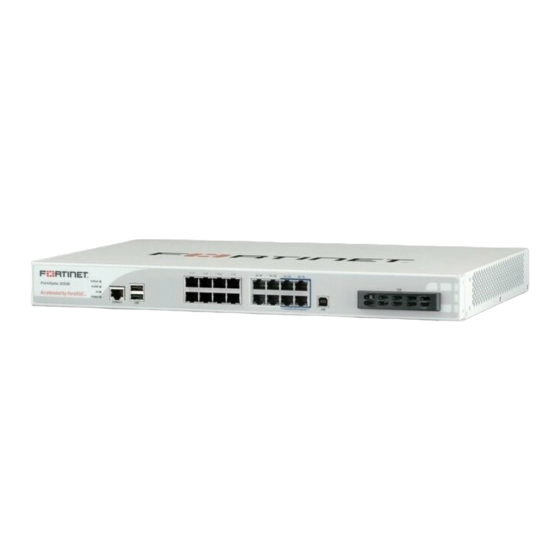
FortiGate 200B-POE
HA
POWER
CONSOLE
USB
LEDs
USB
Console
ports
port
Ground
Connecting
Ensure the FortiGate unit is placed on a stable surface. Connect the following to the FortiGate unit:
•
Connect the RJ-45 to DB-9 serial cable into the Console port on the unit. Insert the other end into the management computer.
•
Insert an ethernet cable into Port 1-8. Insert the other end into a FortiWifi-50B.
•
Insert the ethernet cable into Port 9 to 16. Insert the other end to the router connected to the Internet, or to the modem.
•
Connect the AC power cable to the power supply on the back of the unit.
•
Connect the power cord to a surge protected power bar or power supply.
Note: The AC power supply supports 100-240VAC, 60-50 Hz, 5-4 Amp.
Configuration Tools
Web Config
Web Config is an easy to use management tool. Use it to configure the administrator pass-
word, the interface and default gateway addresses, and the DNS server addresses, add
devices for log collection and configure reports.
Requirements:
•
An Ethernet connection between the Fortinet unit and management computer.
•
A web browser such as FireFox or Internet Explorer on the management computer.
Description
The unit is on.
The unit is off.
The unit is starting up.
The unit is running normally.
The unit is being used in an HA cluster.
A critical error has occurred.
A minor error has occurred.
No errors detected.
POE is in use at that port.
POE is not in use at that port.
Indicates that POE is available.
Port is online.
Port is sending or receiving data.
Connected at 10 Mbps.
Connected at 100 Mbps.
Port is online.
Port is sending or receiving data.
Connected at 1000Mbps.
Connected at 100 Mbps.
Connected at 10 Mbps.
Speed
Protocol
Ethernet
10/100 Base-T
Ethernet
10/100/1000 Base-T
Ethernet
10/100/1000 Base-T
Ethernet
USB
1 / 2
3 / 4
5 / 6
7 / 8
9 / 10
11 / 12
13 / 14
15 / 16
5
7
6
8
POE PORTS
FortiASIC NP2 Powered
POE ports
Ports 9 to 16
STATUS
1
ALARM
READY
2
FortiGate 200B-POE
HA
POWER
CONSOLE
USB
RJ-45 to DB-9 cable
connects to serial
Ethernet cable or
port on management
computer
QuickStart Guide
STATUS
ALARM
FortiGate 200B-POE
HA
POWER
© Copyright 2010 Fortinet Incorporated. All rights reserved.
Products mentioned in this document are trademarks or registered trademarks
of their respective holders.
Regulatory Compliance
FCC Class B Part 15 CSA/CUS
29 March 2010
Description
Connection to the management computer. Provides access to the command line interface (CLI).
POE source capable ports. Supports up to 15W POE devices.
Non-accelerated ports.
ASIC accelerated ports.
Two USB 2.0 ports for firmware backup and installation. One USB 2.0 Client port for management.
Fortinet Storage Module. One SATA hard disk drive slot supports 2.5 inch solid state drives.
FSM
USB
FSM
USB port
module slot
(currently not
AC power
Power
in use)
connection
button
AC LINE
100-240V AC
60-50Hz 5-4A
1 / 2
3 / 4
5 / 6
7 / 8
9 / 10
11 / 12
13 / 14
15 / 16
3
5
7
6
8
4
POE PORTS
FortiASIC NP2 Powered
Straight-through Ethernet
cable connects to hub or
POE
switch on the network
Power cable connects to
Command Line Interface (CLI)
The CLI is a full-featured management tool. Use it to configure the administrator password,
the interface addresses, the default gateway address, and the DNS server addresses. To con-
figure advanced settings, see the Tools and Documentation CD-ROM.
Requirements:
•
The RJ-45 to DB-9 serial connection between the Fortinet unit and the
management computer.
•
A terminal emulation application (HyperTerminal for Windows) on the management com-
puter.
1 / 2
3 / 4
5 / 6
7 / 8
9 / 10
1
3
5
7
READY
2
4
6
8
CONSOLE
USB
POE PORTS
QuickStart Guide
1 / 2
3 / 4
5 / 6
7 / 8
9 / 10
11 / 12
13 / 14
15 / 16
STATUS
1
3
5
7
FortiGate 200B-POE
ALARM
READY
2
4
6
8
HA
POWER
CONSOLE
USB
POE PORTS
FortiASIC NP2 Powered
Tools and Documenation
Copyright 2010 Fortinet Incorporated. All rights reserved.
Trademarks
Straight-through
Ethernet cable
AC Power Cable
FSM
USB
AC LINE
100-240V AC
60-50Hz 5-4A
power supply
FortiGate-200B-POE
11 / 12
13 / 14
15 / 16
FSM
USB
FortiASIC NP2 Powered
01-413-117374-20100120
FortiGate-30B
REGISTER
FSM
USB
Rack-Mount
4 Rubber feet
Brackets
Cable Tie
RJ-45 to
DB-9 Serial Cable
Power Supply (12V)
Advertisement

Related Manuals for Fortinet FortiGate-200B-POE


Summary of Contents for Fortinet FortiGate-200B-POE
- Page 1 Ethernet ASIC accelerated ports. Two USB 2.0 ports for firmware backup and installation. One USB 2.0 Client port for management. Fortinet Storage Module. One SATA hard disk drive slot supports 2.5 inch solid state drives. QuickStart Guide FortiGate-30B 1 / 2...
- Page 2 Connect the Fortinet unit’s internal interface to a management computer Ethernet Use the RJ-45 to DB9 serial cable to connect the Fortinet unit’s Console port to the interface. Use a cross-over Ethernet cable to connect the devices directly. Use straight- management computer serial port.
Need help?
Do you have a question about the FortiGate-200B-POE and is the answer not in the manual?
Questions and answers