Table of Contents
Advertisement
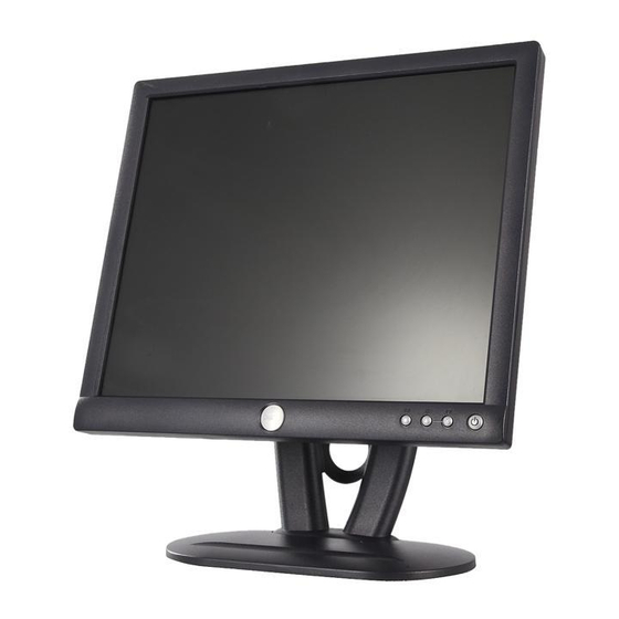
Service Manual
19" LCD Monitor
DELL E193FPc
THESE DOCUMENTS ARE FOR REPAIR SERVICE INFORMATION ONLY.EVERY REASONABLE EFFORT
HAS BEEN MADE TO ENSURE THE ACCURACY OF THIS MANUAL; WE CANNOT GUARANTEE THE
ACCURACY OFTHIS INFORMATION AFTER THE DATE OF PUBLICATION AND DISCLAIMS RELIABILITY FOR
CHANGES, ERRORS OR OMISSIONS.
Advertisement
Table of Contents

Related Manuals for Dell E193FPc


Summary of Contents for Dell E193FPc
-
Page 1: Service Manual
Service Manual 19” LCD Monitor DELL E193FPc THESE DOCUMENTS ARE FOR REPAIR SERVICE INFORMATION ONLY.EVERY REASONABLE EFFORT HAS BEEN MADE TO ENSURE THE ACCURACY OF THIS MANUAL; WE CANNOT GUARANTEE THE ACCURACY OFTHIS INFORMATION AFTER THE DATE OF PUBLICATION AND DISCLAIMS RELIABILITY FOR... -
Page 2: Table Of Contents
Dell E193FPc Table of contents Table of contents ---------------------------------------------------------------------------------------------------------------- 02 Revision List -----------------------------------------------------------------------------------------------------------------------------03 Important Safety Notice ------------------------------------------------------------------------------------------------------------04 1. Monitor Specifications ------------------------------------------------------------------------------------------------------05 2. LCD Monitor Description -------------------------------------------------------------------------------------------------- 05 3. Operation instructions-----------------------------------------------------------------------------------------------------------06 3.1 General Instructions---------------------------------------------------------------------------------------------------------06 3.2 Control buttons -----------------------------------------------------------------------------------------------------------------06 3.3 Adjusting the Picture --------------------------------------------------------------------------------------------------------07 4. -
Page 3: Revision List
Dell E193FPc Revision List Revision Date Revision History TPV model Mar-15-2004 Initial Release T980KLLHJ8DMN Change the panel from LG (LPL 19" (B4KB)) to T980KSLHM8DLN Jul-20-2005 SEC (SEC 19" EX1 (LOO)) Add “Important Safety Notice” Nov-22-2005 Add “Definition Of Pixel Defects”... -
Page 4: Important Safety Notice
REFER TO BACK COVER FOR IMPORTANT SAFETY GUIDELINGS Important Safety Notice Proper service and repair is important to the safe, reliable operation of all Dell Company** Equipment. The service procedures recommended by Dell and described in this service manual are effective methods of performing service operations. -
Page 5: Monitor Specifications
Dell E193FPc 1. Monitor Specifications 48 cm (19”) a-si TFT Active matrix LCD panel, 0.294mm dot pitch. 16 factory presets, 20 new modes Vertical refresh rate 55Hz to 75 Hz Horizontal frequency 30kHz to 80kHz Resolutions: 640 x 480 up to 1280 x 1024... -
Page 6: Operation Instructions
Dell E193FPc 3. Operation instructions 3.1 General Instructions Press the power button to turn the monitor on or off. The other control buttons are located at front panel of the monitor. By changing these settings, the picture can be adjusted to your personal preferences. -
Page 7: Adjusting The Picture
Dell E193FPc 3.3 Adjusting the Picture To set the OSD menu, perform the following steps: Briefly press the SELCT / MENU button to activate the OSD menu. The main menu appears on the screen with icons for the setting functions. -
Page 8: Adjusting Size And Position
Dell E193FPc Calling the Brightness / Contrast setting window using Brightness button. Brightness Setting the brightness of the display With this function you change the brightness of the background lighting. Setting the contrast of the display Contrast With this function you modify the contrast of bright color tones. -
Page 9: Setting Language
Dell E193FPc Setting display of the OSD menu Calling the OSD Set up setting window Horizontal Setting the horizontal position of the OSD menu Position With this function you move the OSD menu to the left or to the right. -
Page 10: Input/Output Specification
Dell E193FPc 4. Input/Output Specification 4.1 Input Signal Connector Pin No. Description Pi N No. Description Red Video Green Video Detector Pin Blue Video DDC-Serial Data DDC-Return H-Sync R-Ground V-Sync G-Ground DDC-Serial Clock B-Ground VGA Connector layout 4.2 Factory Preset Display Modes... -
Page 11: Power Supply Requirements
Dell E193FPc 4.3 Power Supply Requirements A/C Line voltage range 100 V ~ 240 V± 10 % 50 ± 3Hz, 60 ± 3Hz A/C Line frequency range Input Voltage transients 280 volts AC for 10 sec @40℃ Current 0.6A max. at 100V, 0.35A max. at 240 V <... - Page 12 Dell E193FPc 4.4.2 Optical Characteristics For LM190E03-B4 model Ta= 25°C, V =5.0V, fV=60Hz Dclk=54MHz,...
- Page 13 Dell E193FPc For LTM190EX-L01 model The optical characteristics are measured under stable conditions as follows:...
-
Page 14: Block Diagram
Dell E193FPc 5. Block Diagram 5.1 Monitor Exploded View... -
Page 15: Software Flow Chart
Dell E193FPc 5.2 Software Flow Chart... - Page 16 Dell E193FPc 1) MCU Initializes. 2) Is the EEprom blank? 3) Program the EEprom by default values. 4) Get the PWM value of brightness from EEprom. 5) Is the power key pressed? 6) Clear all global flags. 7) Are the AUTO and SELECT keys pressed? 8) Enter factory mode.
-
Page 17: Electrical Block Diagram
Dell E193FPc 5.3 Electrical Block Diagram 5.3.1 Main Board... - Page 18 Dell E193FPc 5.3.2 Inverter/Power Board...
-
Page 19: Mechanical Instruction
Dell E193FPc 6. Mechanical Instruction Tools: 2 Power screwdrivers (φ=5mm,L=60mm); 1 small cross screwdriver; turnbuckle driver; Setting: Power screwdriver torque A=11 kgF. Cm; torque B=6 kgF. Cm Remark Remove stand: Remove the 4 screws and remove the stand ass’y by torque A Remove the rear cover Pry the monitor up then find out the hooks’... - Page 20 Dell E193FPc Remove bezel: Disconnect the Key board connector and remove the bezel Remove the small shield: Remove the screws by Torque B Symbol TPV Part Number Description 095G8014 8 21 wire harness KEPC980KED1 Key Board 015G8140 2 Main Frame...
- Page 21 Dell E193FPc Remove the screw and push the small shield as the arrowhead direction by Torque B or by manual Remove the main frame: Disconnect the back light connectors Remove the four screws and remove the main frame By manual or torque = 3kgF.Cm...
- Page 22 Dell E193FPc Remove the main frame and at the same time disconnect the LVDS connector Fix the Lvds use Black Adhesive Tape Remove the Power board and main board: Remove the eight screws and remove the Power board and main board.
- Page 23 Dell E193FPc Button the harness A and B by Fix Button and screw to main frame. Note: Screw the cable hook as the figure showed and makes sure the line B is above line A. The end Symbol TPV Part Number...
-
Page 24: Schematic
Dell E193FPc 7. Schematic 7.1 Main Board... - Page 25 Dell E193FPc...
- Page 26 Dell E193FPc...
- Page 27 Dell E193FPc...
- Page 28 Dell E193FPc...
-
Page 29: Power Board
Dell E193FPc 7.2 Power Board... - Page 30 Dell E193FPc...
-
Page 31: Layout
Dell E193FPc 8. PCB Layout 8.1 Main Board... - Page 32 Dell E193FPc...
- Page 33 Dell E193FPc...
-
Page 34: Power Board
Dell E193FPc 8.2 Inverter/Power Board... -
Page 35: Key Board
Dell E193FPc 8.3 Key Board... -
Page 36: Maintainability
Dell E193FPc 9. Maintainability 9.1 Equipments and Tools Requirement 1. Voltage meter 2. Oscilloscope 3. Pattern Generator 4. LCD Color Analyzer 5. Service Manual 6. User Manual... -
Page 37: Trouble Shooting
Dell E193FPc 9.2 Trouble shooting 9.2.1 Main Board No display Check Power board, is there DC level output? Measured CN104 pin5 = 5 V? Check U105 pin3=5V, U105 pin2=3.3V? Measured U101 pin 44= 5V? Is there any shortage or cold solder? Measured U105 pin 2= 3.3V? - Page 38 Dell E193FPc Panel Power Circuit Check the PPWR panel power relative circuit, Q105, Q104 In normal operation, Check R171 should have response from when LED =green, R171 should =5V 0V to 5V when we switch the power If PPWR no-response when the power switch...
- Page 39 Dell E193FPc U102-date Output Measured DCLK (pin 57 from U102) DVS, DHS (pin 54,55 from U102) Is the waveform ok? Replace ZAN3XL (U102) or DCLK around 48 MHZ, DVS=60.09Hz, DHS around 80 replace Main board. KHz? (Refer to input signal=640x480@60 Hz, and LED is...
-
Page 40: Power/Inverter Board
Dell E193FPc 9.2.2 Inverter/Power Board No Power Check to CN102 Pin12=12V Check Interface board Check AC line volt 110V or 220V Check AC line Check the voltage of C904(+) Check F901, bridge rectified circuit Check start voltage for the pin3 of IC901... - Page 41 Dell E193FPc No Backlight Check C201 (+) =12V Change F902 Check D201/Q209/Q210/D202/Q211/Q212 Check ON/OFF signal Check Interface board Check U201 pin9=12V voltage of C905(+) Change Q201 or Q202 Check the pin1 of U201 have saw tooth wave Change U201 Check D201(-), D202(-) have the output of square wave at short time.
-
Page 42: Keypad Board
Dell E193FPc 9.2.3 Key Board OSD is unstable or not working Is Keypad board connecting normally? Connect Keypad Board Is Button Switch normally? Replace Button Switch Is Keypad board normally? Replace Keypad Board Check main board... -
Page 43: White Balance, Luminance Adjustment
Dell E193FPc 10.White balance, Luminance adjustment Approximately 2 Hours should be allowed for warm up before proceeding White-Balance adjustment. Before started adjust white balance, please setting the Chroma-7120 MEM. Channel 3 to 6500 K colors, MEM. Channel 4 to 9300 K colors, MEM. -
Page 44: Edid Content
Dell E193FPc 21. Repeat above procedure (item 5,6,7) until chroma 7120 RGB value meet the tolerance =100±2 22. Move cursor to “ Exit/Save” sub-menu and press MENU key to save adjust value and exit. Turn the POWER-button off to on to quit from factory mode. -
Page 45: Isp User Manual
Dell E193FPc 12. ISP (In System Program) User Manual 12.1 Connect ISP Writer preparation action Connect RXD and TXD of PC to RXD (P3.0) and TXD (P3.1) of CPU through RS-232. a. There are two ways to entering Reboot Mode. The settings for Reboot Mode is as follow Both P2.6 P2.7 are LOW and RESET pin is HIGHT. -
Page 46: To Use Isp Writer
Dell E193FPc 12.2 To Use ISP WRITER (take E153FP for example) Press the “–“ key at front bezel and plug the AC power cord in, then the MCU enter ISP mode; a. You will enter the window as follow after executing the ispwriter.exe file. - Page 47 Dell E193FPc b. Click the “Select Chip” button, and choose the type you’re going to program.
- Page 48 Dell E193FPc c. Click the “Select Bank0” button and selecting a file which a binary Format required.
- Page 49 Dell E193FPc d. Select the communication Setting: Port Name e. Click the “ConNect” button.
-
Page 50: Executing Isp
Dell E193FPc f. Click “Program all” to start programming. 12.3. Executing ISP a. “Program All” button that will execute erase and program and verify. Then you can get the window as follow, and click “OK” to complete ISP process. b. Complete the ISP process, click“exit LD”button to reset monitor. -
Page 51: Bom List
Dell E193FPc 13. BOM List T980KLLHJ8DMN Location Part NO Description M1L 330 4128 SCREW M3X4 CBPC980KLLDR CONVERSION BOARD KEPC980KED1 KEY BOARD PWPC1942LGD1 POWER BOARD 11L6036 1 SPACER SUPPORT SCC-24 12L 394 1 FOOT PORON 15G8140 2 MAINFRAME LG 15L5689 3 A... - Page 52 Dell E193FPc 705L980KB34083 19" COVER ASS'Y 750LLG90E03 4 LPL 19" (B4KB) PANEL 40L 457624 1B CPU LABEL AIC980KSLDR MAIN BOARD 40L 45762412B CBPC LABEL C122 67L309V220 3 22UF +-20% 16V C129 67L309V220 3 22UF +-20% 16V C136 67L309V220 3 22UF +-20% 16V...
- Page 53 Dell E193FPc C132 65L0603104 12 0.1UF +-10% 16V X7R C133 65L0603104 12 0.1UF +-10% 16V X7R C134 65L0603104 12 0.1UF +-10% 16V X7R C135 65L0603104 12 0.1UF +-10% 16V X7R C137 65L0603104 12 0.1UF +-10% 16V X7R C138 65L0603104 12 0.1UF +-10% 16V X7R...
- Page 54 Dell E193FPc D110 93L 64 42 P BAV70 SOT-23 D111 93L 39146 LL5232B SMT D112 93L 39146 LL5232B SMT FB101 61L0603220 CHIPR 22 OHM+-5% 1/10W FB102 61L0603220 CHIPR 22 OHM+-5% 1/10W FB103 61L0603220 CHIPR 22 OHM+-5% 1/10W FB104 61L0603000 CHIPR 0OHM +-5% 1/10W...
- Page 55 Dell E193FPc R127 61L0603472 CHIPR 4.7K OHM +-5% 1/1 R128 61L0603101 CHIPR 100 OHM +-5% 1/10 R129 61L0603101 CHIPR 100 OHM +-5% 1/10 R130 61L0603101 CHIPR 100 OHM +-5% 1/10 R131 61L0603272 CHIP 2.7K OHM 1/10W R132 61L0603272 CHIP 2.7K OHM 1/10W...
- Page 56 Dell E193FPc U105 56L 585 4 AIC1117-33CY U106 56G 563 27 AIC1117A-18CY SOT-223 715L1408 1 CN101 95G8014 8 21 WIRE HARNESS LED1 81L 12 1A GP R101 61L 60210152T 100OHM +- 5% 1/6W SW101 77L 600 4 HJ TACT SWITCH TSPE-1...
- Page 57 Dell E193FPc L204 73L 174 30YSA FILTER L902 73L 174 40 LS LINE FILTER L903 73L 253 91 LS CHOKE BY LI SHIN L904 73L 253 91 LS CHOKE BY LI SHIN NR901 61L 58120 WT NTCR 12OHM 20% 2A SCK-1...
- Page 58 Dell E193FPc D203 93G 39S 3 T BZT52-C11 D204 93G 39S 3 T BZT52-C11 F201 61L1206000 CHIPR 0 OHM +-5% 1/4W Q201 57G 760 5B PDTC144WK SOT346 Q202 57G 760 4B PDTA144WK SOT346 Q203 57L 763 3 AO4411 SO-8 BY AOS SMT...
- Page 59 Dell E193FPc R901 61L1206105 CHIP 1MOHM 5% 1/4W R902 61L1206105 CHIP 1MOHM 5% 1/4W R908 61L1206519 CHIPR 5.1OHM +-5% 1/4W R909 61L1206472 CHIP 4.7KOHM 5% 1/4W R910 61L1206472 CHIP 4.7KOHM 5% 1/4W R911 61L1206472 CHIP 4.7KOHM 5% 1/4W R912 61L1206101...
- Page 60 Dell E193FPc J002 61L 60222152T CFR 220 OHM +-5% 1/6W L902 6L 31502 1.5MM RIVET PT201 6L 31502 1.5MM RIVET PT202 6L 31502 1.5MM RIVET Q901 57L 420 PP T 2PA733P Q902 57L 419 PP T 2PC945P R201 61L 60224352T...
- Page 61 Dell E193FPc 90L6064 1 HEAT SINK M1L1730 8128 SCREW M3x8 Q903 57L 667 15 FQPF7N80 TO-220F 96L 29 6 SHRINK TUBE UL/CSA R917 61L 2J39858F 0.390OHM 5% 2W BD901 93G 50460502 KBP206G IC901 56G 379 32 SG6841DZ DIP-8 71L 100509...
- Page 62 Dell E193FPc T980KSLHK8DLN Location Part No. Description 011G6036 1 SPACER SUPPORT SCC-24 012G 394600 FOOT FORON 015G5689502 1 GND LUG (AL) 015G8142 1 MAIN FRAME 023G3178700 1A LOGO 026G 800700 5B BARCODE LABEL 033G4669 GV C POWER BUTTON 033G4817 GV T...
- Page 63 0Q1G 130 8 47 SCREW 0Q1G 330 8 47 SCREW 3X8mm 0Q1G 330 8 47 SCREW 3X8mm M037 S37G5221 19" DELL LCD HINGE ASS'Y CN101 033G3802 8H WAFER 8P RIGHT ANGLE PITCH 2.0 CN104 033G8013 6 H 6P PLUG R/A CN103 033G8027 24 H CONN W TO B12P*2 P*2.0 4505-2...
- Page 64 Dell E193FPc SW104 077G 600 4 HJ TACT SWITCH SW103 077G 600 4 HJ TACT SWITCH SW102 077G 600 4 HJ TACT SWITCH SW101 077G 600 4 HJ TACT SWITCH LED1 081G 12 1A GP CN101 095G8014 8 21 wire harness...
- Page 65 Dell E193FPc PT201 080LL15T 7YSG X'FMR T901 080LL17T 2 TG X'FMR CON102 095G8014 6 19 WIRE HARNESS 705L 560 57 DL D910/D911 ASS'Y 705L 560 61 06 R903 ASS'Y 705L 780 57 DL Q903 ASS'Y 705L 780 61 07 R917 ASS'Y...
- Page 66 Dell E193FPc R129 061L0603101 CHIPR 100 OHM +-5% 1/16W R128 061L0603101 CHIPR 100 OHM +-5% 1/16W R126 061L0603101 CHIPR 100 OHM +-5% 1/16W R125 061L0603101 CHIPR 100 OHM +-5% 1/16W R120 061L0603101 CHIPR 100 OHM +-5% 1/16W R119 061L0603101 CHIPR 100 OHM +-5% 1/16W...
- Page 67 Dell E193FPc R122 061L0603472 CHIPR 4.7K OHM +-5% 1/16W R123 061L0603472 CHIPR 4.7K OHM +-5% 1/16W R127 061L0603472 CHIPR 4.7K OHM +-5% 1/16W R133 061L0603472 CHIPR 4.7K OHM +-5% 1/16W R134 061L0603472 CHIPR 4.7K OHM +-5% 1/16W R135 061L0603472 CHIPR 4.7K OHM +-5% 1/16W...
- Page 68 Dell E193FPc C159 065G0603104 12 CER2 0603 X7R 16V 100N PM10 R C164 065G0603104 12 CER2 0603 X7R 16V 100N PM10 R C149 065G0603104 12 CER2 0603 X7R 16V 100N PM10 R C141 065G0603104 12 CER2 0603 X7R 16V 100N PM10 R...
- Page 69 Dell E193FPc D106 093G 6433P BAV99 715L1280 E main board 090G6064 1 HEAT SINK D911 093G 60217 FMB29L 10A 100V SANKEN D910 093G 60245 SP10150 0M1G1730 8128 SCREW M3x8 R903 061G152M10458F 100K OHM 5% 2W 096G 29 6 H.S. TUBE...
- Page 70 Dell E193FPc R237 061L0603471 CHIPR 470 OHM+-5% 1/16W R236 061L0603471 CHIPR 470 OHM+-5% 1/16W R219 061L0603471 CHIPR 470 OHM+-5% 1/16W R218 061L0603471 CHIPR 470 OHM+-5% 1/16W R209 061L0603472 CHIPR 4.7K OHM +-5% 1/16W R208 061L0603472 CHIPR 4.7K OHM +-5% 1/16W...
- Page 71 Dell E193FPc C212 065G0805105 22 CHIP 1UF 25V X7R 0805 C203 065G0805105 22 CHIP 1UF 25V X7R 0805 C210 065G0805105 22 CHIP 1UF 25V X7R 0805 C220 065G0805105 22 CHIP 1UF 25V X7R 0805 C211 065G0805105 22 CHIP 1UF 25V X7R 0805...
- Page 72 Dell E193FPc R225 061G 17210252T 1K OHM 5% 1/4W R224 061G 17210252T 1K OHM 5% 1/4W R916 061G 17210352T CFR 10KOHM +-5% 1/4W R924 061G 20024252T 2.4KOHM 1% 1/4W R922 061G 20033352T 33KOHM 1% 1/4W R923 061G 20036252T 3.6KOHM 1% 1/4W...
- Page 73 Dell E193FPc Diversity of T980KALHK8DLN compared with T980KSLHK8DLN Location Part No. for TPV Description 015G8142 2 MAIN FRAME E089B 089G1738GAA 16 SIGNAL CABLE 095G8018 30590 WIRE HARNESS 750GLU90N04 2Z AU 19" V2D ZBD PANEL CBPC980KALDR CONVERSION BOARD PWPC1942AUD1 POWER BOARD...
-
Page 74: Definition Of Pixel Defects
Dell E193FPc 14. Definition Of Pixel Defects Type 1. LM190E03 Dot Defect Bright Dot Dark Dot Total amount of Dot Defects -------------------------5 Max(Combination) Polarizer Defects... - Page 75 Dell E193FPc Foreign Material Line Defect Bezel Appearance Others Type 2. LTM190EX-L01...
- Page 76 Dell E193FPc...
- Page 77 Dell E193FPc...
- Page 78 Dell E193FPc...
Need help?
Do you have a question about the E193FPc and is the answer not in the manual?
Questions and answers