Table of Contents
Advertisement
Quick Links
Building Air-Conditioners Control System
LM ADAPTER
Model : LMAP04-E
Before using the unit, please read this Installation
Manual carefully to ensure correct operation. Store this
Installation Manual in a location that is easy to find.
Echelon
®
,LON
®
,L
W
ON
Echelon logo are trademarks of Echelon Corporation
registered in the United States and other countries.
LonMaker™ and the Lon Users logo are trademarks of
Echelon Corporation.
®
,Neuron
®
,3150
®
ORKS
Contents
Safety Precautions ···················································1,2
1 .Parts Include ····························································3
2 .Specifications ···························································3
2 -1 External View ···················································3
2 -2 Environment Specifications ·····························3
2 -3 Connected Air Conditioning Equipment ··········4
2 -5 Network Variable Specifications ·······················5
3.Installation ·······························································6
3 -1 Locally Procured Parts ·····································6
3 -2 Installation Method ···········································7
3 -3 Wiring Methods ················································8
3 -4 Electrical Wiring ···············································9
4 .System Settings ·····················································11
4 -2 If used together with system controller ···········12
4 -3 Initialization Settings of L
5 .Confirming Operation ·············································14
5 -1 Flow of Onsite Adjustments ····························14
5 -3 Preparation and Setting ·································14
5 -4 Test Run ·························································15
6 .Troubleshooting ······················································16
6 -1 Abstract ··························································16
6 -2 Troubleshooting ·············································17
6 -3 Error Code list ················································19
Appendix : Test run check sheet ······························20
and the
Installation Manual
Network Specifications ················4
®
®
Advertisement
Table of Contents
Troubleshooting

Related Manuals for Mitsubishi Electric LMAP04-E

Summary of Contents for Mitsubishi Electric LMAP04-E
-
Page 1: Table Of Contents
Building Air-Conditioners Control System LM ADAPTER Model : LMAP04-E Installation Manual Contents Safety Precautions ···················································1,2 1 .Parts Include ····························································3 2 .Specifications ···························································3 2 -1 External View ···················································3 2 -2 Environment Specifications ·····························3 2 -3 Connected Air Conditioning Equipment ··········4 2 -4 L Network Specifications ················4... -
Page 3: Safety Precautions
Safety Precautions • Before installing this unit,make sure you read all the “Safety Precautions”. • This manual describes the installation of LM ADAPTER and wiring to the outdoor unit. • Please read the installation manual of air-conditioning units with regards to the installation method of air-conditioning units. •... - Page 4 CAUTION Do not install the unit where combustible gas may leak. When installing the unit in a hospital, communication If the gas leaks and accumulates around the unit, an station, or similar place, provide sufficient protection explosion may result. against noise. The inverter equipment, private power generator, high- Do not use in any special environment.
-
Page 5: Parts Include
1. Parts Include Verify that the following parts are appended to the product. Binding band Name Main Unit Installation manual Shape Quantity · The external interface file (XIF) is necessary for the product. Upon verifying the 16-digit program ID (PID) which is bonded on the board, please contact your dealer. 2. -
Page 6: Connected Air Conditioning Equipment
2-3 Connected Air Conditioning Equipment Item Description Connected Equipment Model Function (Monitor/Operation) CITY MULTI S series Y series HP series R2 series WY series WR2 series HVRF series LOSSNAY OA Processing Units A-control unit (Mr.Slim) (Requires an adapter) AK-control unit (Mr.Slim) K-control unit Room air conditioner (RAC) Housing air conditioner (HAC) -
Page 7: Network Variable Specifications
2-5 Network Variable Specification The following are applied to the CITY-MULTI type indoor unit of the Multiple split type air conditioners CITY MULTI. When Mr.SLIM, LOSSNAY, or Air To Water is used, please refer to the “Network Variable Specification” in details. -
Page 8: Installation
3. Installation <Notes> Read and understand “Safety Precautions ” before performing the installation. 3-1 Locally Procured Parts Prepare the following prior to installing the unit. Locally procured parts Contents Power wire Use sheathed vinyl cord or wire. and ground wire Wire type ………... -
Page 9: Installation Method
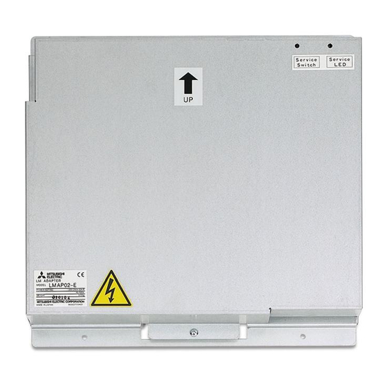
3-2 Installation Method • LM ADAPTER is not waterproof type. • LM ADAPTER shall be installed in a control panel box (steel : thickness 1 mm (3/64 in) or more). Please prepare the control panel box in consideration with installation space as shown in the Fig. (Install in an area capable of withstanding a 3.3 kg load.) The unit shall be also installed in vertical direction only indicated by arrow making on the cover as shown in the Fig. -
Page 10: Wiring Methods
3-3 Wiring Methods Use wire clamps provided to secure the wires and prevent external force from being conveyed by the wire to the wire connections. * External force could cause deformation or damage to the terminal blocks. Note1 Connect the power supply wires and grounding wire CN605 to “L”, “N”... -
Page 11: Electrical Wiring
3-4 Electrical Wiring Breaker 3A (Wink) LED001 LED003 LED002 LED004 SWU2 SWU1 Unit Body (1st digit) (2nd digit) Power supply 220-240V~/N 50/60Hz L.B. CN33 CN31 CN605 ZNR2 LED009 (WDT) M-NET Power Supply CN71 LED201 ZNR1 LEDL AC250V (18007RST) (Service CN40 CN41 DSA1 2A F... - Page 12 Explanation of function switch Note: Function switch setting of LM ADAPTER is different according to the management item of the equipment connected with L . Carefully set the system. ® ORKS Factory Switch name Function Note Set timing setting Before power SW1-1 Function switch local prohibit effective...
-
Page 13: System Settings
4. System Settings This chapter only describes the system settings of this product. For the installation work and electrical work, refer to the last chapter “3. Installation”. <Notes> Read and understand the contents of Chapter 1 “Safety Precautions” before performing the installation. The system setting is different depending on the system configuration connected. -
Page 14: If Used Together With System Controller
4-2 If used together with system controller. Power supply unit Shielded wire ground ❇ OC : Outdoor Unit Centralized controller : Switch Position (System controller) as is as is LM ADAPTER SW2-1 [OFF] M-NET transmission line CN41 (Centralized control line) CN41 1 2 3 4 5 6 7 8 9 10 SW1-2 [ON]... -
Page 15: On Works ® Network
4-3 Initialization Settings of L ® Network ORKS For details, refer to “FT3120/FT3150 Smart Transceiver Data Book” of Echelon Corporation. For reference, the system specifications and Transmission specifications are described. (1) Termination of L ® ORKS The product can be set with the termination of L ®... -
Page 16: Confirming Operation
5. Confirming Operation 5-1 Flow of Onsite Adjustments …… Test run by unit and local remote controller Refer to 5-4 (1) …… Refer to 5-4 (2) Test run by LM ADAPTER ® …… Refer to 5-4 (3) Test run from the L network ORKS ®... -
Page 17: Test Run
5-4 Test Run Perform the test run according to the test procedure of the test run check list. (1) Test run of indoor units by local remote controller Perform the test run of the indoor units by using the local remote controller or system controller. * Confirm that all indoor units are running normally. -
Page 18: Troubleshooting
6. Troubleshooting 6-1 Abstract If LM ADAPTER does not properly operate, first check the following contents. Item Normal state Contents to check Check the Main Power Switch to the LM ADAPTER is not turned off, any LED009 connectors (CN605, CN65, CN32, CN33, CN31, CN71) are disconnected (WDT) and for a blown fuse (F). -
Page 19: Troubleshooting
6-2 Troubleshooting Error content Cause Checking method and remedy (1) It takes time for the initial processing It can take about 15 minutes for the initial processing LED002 is ON to complete (normal). to complete. Wait until the initial processing finishes. (2)Setting on M-NET side is not properly Verify that the test operation of the air conditioner is completed. - Page 20 Error content Cause Checking method and remedy Independent/interl (1)The LM ADAPTER is not completely Refer to 2-(1). ocked LOSSNAY initialized. can not be (2)Setting on M-NET side is not properly Refer to 2-(2). operated from the completed. LON side. (3)If system controller is used together Refer to 2-(3).
-
Page 21: Error Code List
6-3 Error code list Error Display of trouble Error content Symptom Cause Checking method and remedy code 6600 M-NET remote controller, M-NET • If it has been • If there are two or more • Check that there are no MA remote controller, duplication confirmed that a unit... -
Page 22: Appendix : Test Run Check Sheet
Appendix : Test run check sheet Test run check sheet ® Test run of units (SW1-9) Operation from L network Confirmation of operating status ORKS Unit MEMO OFF Operation Operation address Intake Error temperature temperature temperature mode mode * Check the building control system functions beforehand and check off each operation as it is tested. For the check list, you can either copy this sheet or make a new check list based on this sheet. - Page 24 EU regulations: 2004/108/EC Restriction of Hazardous Substances • 2011/65/EC HEAD OFFICE : TOKYO BLDG. , 2-7-3, MARUNOUCHI, CHIYODA-KU, TOKYO 100-8310, JAPAN Authorized representative in EU: MITSUBISHI ELECTRIC EUROPE B.V. HARMAN HOUSE, 1 GEORGE STREET, UXBRIDGE, MIDDLESEX UB8 1QQ, U.K. WT07000X01...