Table of Contents
Advertisement
Advertisement
Table of Contents

Summary of Contents for Staubli CS8C
- Page 1 CS8C Controller Instruction manual D28070504A – 26/03/2009 CS8C © Stäubli 2009...
- Page 2 Documentation addenda and errata can be found in the "readme.pdf" document delivered with the controller's CdRom. 2 / 248 © Stäubli 2009 – D28070504A CS8C...
- Page 3 CONNECTIONS ..............46 3/ 248 CS8C © Stäubli 2009 – D28070504A...
- Page 4 4 / 248 © Stäubli 2009 – D28070504A CS8C...
-
Page 5: Table Of Contents
6.14 CONTROLLER BACKUP............152 5/ 248 CS8C © Stäubli 2009 – D28070504A... - Page 6 6 / 248 © Stäubli 2009 – D28070504A CS8C...
-
Page 7: Table Of Contents
STÄUBLI ROBOTICS STUDIO (SRS) ........ - Page 8 8 / 248 © Stäubli 2009 – D28070504A CS8C...
- Page 9 Chapter 1 - Introduction CHAPTER 1 INTRODUCTION 9 / 248 CS8C © Stäubli 2009 – D28070504A...
- Page 10 10 / 248 © Stäubli 2009 – D28070504A CS8C...
-
Page 11: Foreword
Stäubli CS8C controller. It provides help for the persons working on the equipment, for reference purposes only. This is because correct understanding of this document and use of the Stäubli CS8C controller imply that the staff concerned have acquired the necessary knowledge by following a "robots" training course provided by Stäubli. -
Page 12: Definition Of The Elements Around The Robot Cell
Staff: identifies the persons specifically employed and trained to install, operate, and service the Stäubli robot cell. User: refers to the persons or the company responsible for operating the Stäubli robot cell. Operator: refers to the person who starts or stops the robot, or controls its operation. 12 / 248 © Stäubli 2009 – D28070504A CS8C... - Page 13 Chapter 1 - Introduction 13 / 248 CS8C © Stäubli 2009 – D28070504A...
- Page 14 14 / 248 © Stäubli 2009 – D28070504A CS8C...
- Page 15 Chapter 2 - Description of the controller CHAPTER 2 DESCRIPTION OF THE CONTROLLER 15 / 248 CS8C © Stäubli 2009 – D28070504A...
- Page 16 16 / 248 © Stäubli 2009 – D28070504A CS8C...
-
Page 17: Identification
For all requests concerning information, replacement part orders, or requests for intervention, please state the type and the serial number of the machine concerned, as set out on the manufacturer's plate. 17 / 248 CS8C © Stäubli 2009 – D28070504A... -
Page 18: Location And Description Of The Main Components
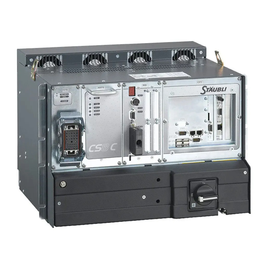
LOCATION AND DESCRIPTION OF THE MAIN COMPONENTS 2.2.1. THE CONTROLLER The CS8C controller is made up of a processor (5), the intelligent part of the installation. The processor controls the robot via digital power amplifiers (1) dedicated to each axis of the arm. - Page 19 Modes of operation are selected from the WMS front panel which has to be installed permanently outside of the cell. The removable 3-position keyswitch prevents from changing the mode when it is not allowed. 19 / 248 CS8C © Stäubli 2009 – D28070504A...
- Page 20 20 / 248 © Stäubli 2009 – D28070504A CS8C...
- Page 21 Chapter 3 - Safety CHAPTER 3 SAFETY 21 / 248 CS8C © Stäubli 2009 – D28070504A...
- Page 22 22 / 248 © Stäubli 2009 – D28070504A CS8C...
-
Page 23: Reminder Concerning The Safety Standards
Speed on approach towards the human body • Standard EN 61 000-6-4 Electromagnetic compatibility - Emission • Standard EN 61 000-6-2 Electromagnetic compatibility - Immunity • Standard CEI 34-1 Electrical rotating machines 23 / 248 CS8C © Stäubli 2009 – D28070504A... - Page 24 For the UL version: • Standard UL 1740 Robots and Robotics Equipment • Standard RIA15-06 American National Standard for Industrial Robots and Robot Systems. Safety Requirements. • Standard CSA Z434-03 Industrial Robots and Robot Systems. General Safety Requirements. • Standard NFPA 79 Electrical standard for industrial machinery •...
-
Page 25: Safety Directives Concerning To The Work Environment
It is thus necessary to make sure that no persons or obstructions are present in the robot's work area when the arm is powered up. 25 / 248 CS8C © Stäubli 2009 – D28070504A... -
Page 26: Safety Directives Concerning To Staff Protection
• Disconnect all the electrical and pneumatic power supplies before carrying out any work on the controller or the arm. To turn of power, set the CS8C main switch to the "0" position. To prevent inadvertent during the service operation, the main switch must be locked in 0 position using a padlock whose key is to be kept by the person carrying out the service operation. - Page 27 (see the "Integration" chapter). When the system is used without the MCP, these messages/warnings can only be consulted via the application program (see chapter 5). 27 / 248 CS8C © Stäubli 2009 – D28070504A...
-
Page 28: Safety Directives Concerning To Protection Of The Equipment
The same components will pass the "on/off" test successfully, as carried out during repairs, but the problem will reappear again once on site. 28 / 248 © Stäubli 2009 – D28070504A CS8C... - Page 29 18 kV 11 kV 1,5 kV Cellular polyurethane CHARGE SOURCES Work surfaces Packaging Floors Handling Chairs Assembly Carriages Cleaning Clothes Repairing PARTS SENSITIVE TO STATIC CHARGES Electronic cards Power supplies Encoders 29 / 248 CS8C © Stäubli 2009 – D28070504A...
- Page 30 The wrist straps are supplied as part of the standard equipment for the robot. CAUTION: Use an electrostatic wrist strap and an anti-static mat connected to the cabinet during all handling of boards or components. 30 / 248 © Stäubli 2009 – D28070504A CS8C...
- Page 31 Chapter 3 - Safety 31 / 248 CS8C © Stäubli 2009 – D28070504A...
- Page 32 32 / 248 © Stäubli 2009 – D28070504A CS8C...
- Page 33 Chapter 4 - Installation CHAPTER 4 INSTALLATION 33 / 248 CS8C © Stäubli 2009 – D28070504A...
- Page 34 34 / 248 © Stäubli 2009 – D28070504A CS8C...
-
Page 35: Robotized Cell Environment
The characteristics of the power supply and the grounding terminals must comply with the manufacturers' specifications. Each robotized cell must be equipped with means of separating each of its power sources. 35 / 248 CS8C © Stäubli 2009 – D28070504A... -
Page 36: On-Site Preparation
CAUTION: Make sure that the voltage supplied corresponds to the voltage shown on the manufacturer's plate of the CS8C controller. When making the connections, the ground wire must be connected first. Power rating to be installed:... - Page 37 If these conditions of cleanness and temperature in particular are not complied with, the controller must be integrated in a closed area in which the necessary conditions can be provided: A cooled industrial frame. If CS8C is enclosed in a IP54 cabinet, the door of this external chassis has to remain closed during operation.
- Page 38 4.2.4. CONTROLLER FOOT PRINT AND FITTINGS The CS8C controller can be simply placed on the floor, in compliance with its environmental constraints, or fitted in a 19" frame as shown in the layout below, to meet the airflow constraints. For easier maintenance, we recommend slides to hold the controller in place while it is not kept in a vertical position by its fastening points.
- Page 39 Chapter 4 - Installation 4.2.4.2. CS8C FOR RX160 ARM Detail: A Scale: 1:1 Figure 4.2 39 / 248 CS8C © Stäubli 2009 – D28070504A...
- Page 40 CS8C controller for the RX160. Note: The surface used for the installation must be horizontal and free from vibrations. If the CS8C controller is integrated in an industrial frame ensuring that the surrounding air is dust-free, the filter (3) must be removed. Figure 4.3...
-
Page 41: Unpacking And Handling
Chapter 4 - Installation 4.3. UNPACKING AND HANDLING 4.3.1. PACKAGING FOR THE CS8C CONTROLLER CS8C FOR TX, RS CS8C FOR RX160 900 x 640 x 570 mm 900 x 815 x 570 mm Standard packaging 354 x 252 x 224 in... -
Page 42: Fixing The Mcp
CAUTION: If MCP is not connected to the controller, it shall be removed from the cell to avoid having a non-operating E-Stop push button. 42 / 248 © Stäubli 2009 – D28070504A CS8C... - Page 43 Chapter 4 - Installation Holder measurements: Figure 4.5 43 / 248 CS8C © Stäubli 2009 – D28070504A...
-
Page 44: Fixing The Wms
To comply with the UL requirements, it cannot be provided or modified by the user / integrator. The WMS is designed to be installed on a plate with following dimensions: 4 * M4 52 x 93 mm hole 104 mm Figure 4.7 44 / 248 © Stäubli 2009 – D28070504A CS8C... - Page 45 Figure 4.8 When installed, the board side has to be protected against direct contacts and dusty environment. The cable between WMS and CS8C has a connector on both sides. It has to be connected to J113 on CS8C (RSI2 board).
-
Page 46: Connections
4.6.1. CONNECTION TO THE MAINS POWER SUPPLY CAUTION: Make sure that the voltage supplied corresponds to the voltage shown on the manufacturer's plate of the CS8C controller. Use a cable appropriately rated to the power mentioned on the identification plate, and protect the line accordingly. - Page 47 • Never replace these fuses with fuses of a higher rating or with different characteristics (see the "replacement parts" section). Note: Am means "slow-acting fuse" according to IEC 269-1.2. AT means "slow-acting fuse" and AF "quick-acting fuse" according to IEC 127-2. 47 / 248 CS8C © Stäubli 2009 – D28070504A...
- Page 48 In the event of soiling, the only cleaning product to be used is water. Never use alcohol. DANGER: Do not stand with your eyes directly opposite the optical fiber when it is lit, in order to avoid damage to the eyes. 48 / 248 © Stäubli 2009 – D28070504A CS8C...
- Page 49 The brackets used to hold the controller in place also provides protection from electrical noise. It is thus useful for the fastenings (8) to be linked to the ground circuit of the cell as a whole. Note: For RS robots, there are also Inputs/Outputs available on the arm. 49 / 248 CS8C © Stäubli 2009 – D28070504A...
- Page 50 4.6.4. CABLE INLETS AND OUTLETS The connections for the CS8C controller are on the front panel. They must then be protected by backshells with good levels of mechanical strength and the cables have to be attached to the frame of the cell to avoid constraints on connectors.
- Page 51 The length of the cables must be taken into account to facilitate maintenance. Interconnection cable: • Cable Ø: 25 mm • Connector passage Ø: 90 mm WMS cable: • Cable Ø: 7 mm • Connector passage Ø: 25 mm 51 / 248 CS8C © Stäubli 2009 – D28070504A...
- Page 52 52 / 248 © Stäubli 2009 – D28070504A CS8C...
- Page 53 Chapter 5 - Integration CHAPTER 5 INTEGRATION 53 / 248 CS8C © Stäubli 2009 – D28070504A...
- Page 54 54 / 248 © Stäubli 2009 – D28070504A CS8C...
-
Page 55: Emergency And Safety Stop Channels
• Either the status of MCPES, WMSES and UESA (configuration 1: the doors of the cell not included). • Or the status of MCPES, WMSES, UESA and (USEREN or DOOR) (configuration 2: the doors of the cell are included). This is the default configuration when CS8C is delivered. To modify this configuration, refer to chapter "Software configuration". - Page 56 The status of the stop channels is displayed on the control panel. Note: In this display, an active input (ON) shows that an emergency stop has been activated (channel in open position). 56 / 248 © Stäubli 2009 – D28070504A CS8C...
- Page 57 Chapter 5 - Integration Emergency stop channels Figure 5.1 57 / 248 CS8C © Stäubli 2009 – D28070504A...
- Page 58 RSI2 SUBD-37M J109-18 24V_In J109-37 24Vfus + 24 VDC 250 mA 220uF 22-26 VDC 50mA 0 VDC J109-19 Internal External 24VDC 24VDC for E-Stop lines Figure 5.2 58 / 248 © Stäubli 2009 – D28070504A CS8C...
- Page 59 Chapter 5 - Integration Figure 5.3 59 / 248 CS8C © Stäubli 2009 – D28070504A...
- Page 60 Figure 5.4 60 / 248 © Stäubli 2009 – D28070504A CS8C...
- Page 61 Figure 5.5 CAUTION: The CS8C controller is supplied with a "shorting connector" for J109 that can be used to power up the robot without wiring up the emergency stops. This connector is provided for diagnosis purposes only. It must be replaced by suitable wiring on the emergency stop circuits.
-
Page 62: Basic Inputs/Outputs
Operational current range 0 to 5 µA "Off" state current range 33 to 240 µA "On" state current range 100 kΩ Impedance Response time for equipment + software 6,5 ms maxi 62 / 248 © Stäubli 2009 – D28070504A CS8C... - Page 63 Voltage drop at output when I = 250 mA 1,2 V maxi On state output resistance 5 µA Maximum leakage current in off state Response time for equipment + software 50 µs Limit output current (overload) 63 / 248 CS8C © Stäubli 2009 – D28070504A...
- Page 64 Manual mode Manual mode MANU- invalid PS1 PS2 Note (3) USERPS1+ Arm power-up USERPS1- Arm not Arm powered USERPS2+ powered USERPS2- Note (2) USER-IN X USER-IN 1 + USER-IN 1 - 64 / 248 © Stäubli 2009 – D28070504A CS8C...
- Page 65 Note (4) lines Note (1): This information is configurable (see chapter 5.1). Note (2): See figure 5.6. Note (3): Max. 48V AC/DC/ 0.5A. Note (4): Refer to chapter 5.1 and figure 5.2. 65 / 248 CS8C © Stäubli 2009 – D28070504A...
-
Page 66: Encoder Input
To install a new board: • Extract and open computer part (CPT). • Select board address with J324 jumper. • Connect the board to STARC with cables provided with the board. Figure. 5.8 66 / 248 © Stäubli 2009 – D28070504A CS8C... - Page 67 The current position e00CurrPos (Current position) then takes the value e00PrstPos, and the e00EnPrst Input/Output is deactivated. The recovery sequence is not saved by the system; it is necessary to repeat it each time the controller is powered 67 / 248 CS8C © Stäubli 2009 – D28070504A...
- Page 68 The e00PowerErr digital output is activated when the encoder power supply is not correct. To reactivate the encoder after an error, it is necessary to reset it using the e00RstErr digital output. 68 / 248 © Stäubli 2009 – D28070504A CS8C...
- Page 69 Power supply for the controller The SECTEUR_OK input is activated when the controller is powered up. When the power supply to the CS8C controller is cut off, the SECTEUR_OK signal is deactivated about 80ms before the power is actually cut off. The SECTEUR_OK input may also be deactivated temporarily if the power supply voltage is too low.
-
Page 70: Rs Robots
5.3.1. INSTALLATION OF THE OPTION The option includes: • A CAN board to be installed in the CS8C computer module. The board is provided with a cable and mounting screws. • A cable between CS8C and the base of the arm. - Page 71 Chapter 5 - Integration 5.3.1.1. INSTALLATION OF CAN BOARD IN COMPUTER • Refer to 8.9.2 to remove and open CS8C computer module. • Plug the cable attached to the CAN board to CPU board. Figure 5.11 • Install the CAN board on B1 location of front plate using the 2 screws provided with the board.
- Page 72 5.3.1.2. INSTALLATION OF CABLE • The cable has to be connected to J211 on CS8C computer module and on J1202 on arm. 5.3.1.3. INSTALLATION OF I/O BOARD IN THE ARM Remove the 2 side covers and the outer cover of the forearm.
- Page 73 Type of connections Molex 2.50 mm SPOX: • 2 x 8-pin, article: 22-01-1084 • 1 x 4-pin, article: 22-01-10449 These connections are designed for use with the connection tool option (TC). 73 / 248 CS8C © Stäubli 2009 – D28070504A...
- Page 74 +24 VDC Configuration bridge for the ASI power supply Remove the bridge if the ASI power supply is provided by an external source. 74 / 248 © Stäubli 2009 – D28070504A CS8C...
- Page 75 • Response time (hardware and software): 6 ms maximum • Analog inputs: • Input voltage: ± 10 V • Resolution: 78 mV • Accuracy: 5 % • Response time: 6 ms 75 / 248 CS8C © Stäubli 2009 – D28070504A...
- Page 76 Module in pre-operational status The CIO board has configuration switches whose positions must be as follows: • 1, 7, 8 = on • 2, 3, 4, 5, 6 = off (see figure 5.13) 76 / 248 © Stäubli 2009 – D28070504A CS8C...
- Page 77 Chapter 5 - Integration Switches Figure 5.13 77 / 248 CS8C © Stäubli 2009 – D28070504A...
- Page 78 5.3.1.8. ARMIO BOARD LED3 LED2 LED1 10 11 12 13 14 CORRESPONDENCE cAout cAout 1 cDout0 cDout1 cDout2 cDout3 cDout4 cDout5 cDout6 cDout7 +24 VDC cAout2 cAout3 78 / 248 © Stäubli 2009 – D28070504A CS8C...
- Page 79 • Response time (hardware and software): 6 ms maximum • Analog inputs: • Input voltage: ± 10 V • Resolution: 78 mV • Accuracy: 5 % • Response time: 6 ms 79 / 248 CS8C © Stäubli 2009 – D28070504A...
- Page 80 Module in pre-operational status The ARMIO board has configuration switches whose positions must be as follows: • 1, 7, 8, 9 = on • 2, 3, 4, 5, 6 = off (see figure 5.13)76 80 / 248 © Stäubli 2009 – D28070504A CS8C...
- Page 81 Chapter 5 - Integration Switches Figure 5.14 81 / 248 CS8C © Stäubli 2009 – D28070504A...
- Page 82 X14.2 cDout2 White, violet X14.2 cDout3 Blue X14.2 cDout4 Black X14.2 cDout5 White, grey X14.2 cDout6 White, blue X14.2 cDout7 White, red X14.1 +24 V X14.3 Violet X14.1 Brown Green, yellow 82 / 248 © Stäubli 2009 – D28070504A CS8C...
-
Page 83: As-I Digital Inputs/Outputs (Rs Arms)
Such AS-I configuration tools can be found by AS-I devices manufacturers. • The slave modules present on the AS-I bus cannot be detected automatically by the CS8C controller. You have to declare them to the controller (see Configuration hereafter). -
Page 84: Digital Bio Input/Output Board (Optional Extra)
The signals are numbered from 0 to 15 on each board and they correspond to outputs 0 to 15 and then 16 to 31. CAUTION: The Inputs/Outputs have to be powered by a rectified, filtered external power source (not supplied). Wiring the I / 0s Wiring is described in the "Electric Wiring" manual. 84 / 248 © Stäubli 2009 – D28070504A CS8C... - Page 85 15 ms maxi Equipment and software response time 2,5 kV / 4 mm Insulation voltage / Leakage current Note: The characteristics of the input current are given for informational purposes only. 85 / 248 CS8C © Stäubli 2009 – D28070504A...
- Page 86 3.9k J601-26 IN 5 J601-8 3.9k IN 6 3.9k IN 7 J601 BIO board - Inputs Figure 5.16 Note: The inputs are numbered from 0 to n on each Input/Output board. 86 / 248 © Stäubli 2009 – D28070504A CS8C...
- Page 87 A, L = 1 mA) Maximum DC short circuit current 0.7 A < llim < 2.5 A lovpk < 4 A Peak short circuit current 2.5 kV / 4 mm Insulation voltage / Leakage current 87 / 248 CS8C © Stäubli 2009 – D28070504A...
- Page 88 OUT 1 load OUTPWR1 OUT 2 load OUTPWR1 OUT 3 load OUTRET1 J602 BIO board - Outputs Figure 5.17 Note: The outputs are numbered from 0 to n on each input/output board. 88 / 248 © Stäubli 2009 – D28070504A CS8C...
- Page 89 Chapter 5 - Integration Figure 5.18 J601 J602 Figure 5.19 89 / 248 CS8C © Stäubli 2009 – D28070504A...
- Page 90 • Replace the RSI board. • The presence of the BIO board is detected automatically by the CS8C cabinet on start-up. The "Control panel" application enables you to see that the board is in place and check the status of its Inputs/Outputs.
-
Page 91: Field Bus
This tool enables you to configure the field bus board on the one hand, and to generate a ConfigTag.xml file on the other hand. The file must be copied by Ftp in the /usr/applicom/io directory of the CS8C controller. If this file is present on start-up, the Inputs/Outputs of the field bus are displayed on the control panel and are directly accessible via a VAL3 application. - Page 92 Field bus errors are shown by messages on the MCP, which can also be accessed using the "events logger " application. These errors start with the word "FIELDBUS", followed by a CS8C diagnosis, the identification of the board, the equipment and the channel concerned, and the Status (Applicom diagnosis).
- Page 93 Negative layer 2 acknowledgement from the equipment (NACK). PROFIBUS: RDH (Response FDL/FMA1/2 Data High), remote equipment resources insufficient to deal with the data received, high priority response. Incorrect parameter sent to the function Wrong number of variables. 93 / 248 CS8C © Stäubli 2009 – D28070504A...
- Page 94 The master DeviceNet is offline (no power supply detected or the CAN component of the applicom interface set to "Bus Off"). Check the wiring and the Baud Rate for the network. 94 / 248 © Stäubli 2009 – D28070504A CS8C...
- Page 95 The equipment does not correspond to the configuration. Check the equipment and the bandwidth of the connections. Driver not accessible. Operating mode not accepted. The applicom interface is already in use. Local reading buffer not initialized by the IO_RefreshInput function. 95 / 248 CS8C © Stäubli 2009 – D28070504A...
-
Page 96: Programmable Logic Controller (Plc Option)
5.7.2. OPERATION IN THE CS8C CONTROLLER PLC cycle The PLC program in the CS8C has access to all the digital and analog inputs and outputs in the system. It can communicate with a VAL3 program via the analog or digital outputs of the system. - Page 97 Inputs/Outputs are refreshed with each PLC cycle, each VAL3 synchronous cycle and each VAL3 asynchronous cycle. PLC utility for the MCP The main menu of the CS8C includes a "PLC" utility that displays the main characteristics of the PLC program being executed: •...
- Page 98 • The direction field must be set to 0 for an input and 1 for an output. Automatic creation of the PLC variables on the basis of the Inputs/Outputs for the CS8C controller can be carried out using the SRS import tool (Tools > PLC > Import) (see figure 5.21).
- Page 99 • If necessary, update the CS8C emulator inputs and outputs using the SRS downloading tool. • Create or load the desired PLC application (File > Create / Open a PLC project). The CS8C Inputs/Outputs emulated are then displayed in the left-hand frame.
- Page 100 If a PLC program is already being executed, it may be necessary to stop it via the programming environment before downloading the new program. The download also copies the PLC program on the CS8C, which means that the last program downloaded is executed automatically when the controller is started up.
-
Page 101: Ethernet Link
5.8.1. CONFIGURATION The CS8C has 2 Ethernet ports, J204 and J205. The IP address of each of these ports can be modified via the control panel. The modification takes effect immediately. On delivery, the first port is configured with the address 192.168.0.254 (mask 255.255.255.0) and the second one with the address 172.31.0.1 (mask 255.255.0.0). - Page 102 Modbus Tcp errors are shown by messages on the MCP, which can also be displayed using the "events logger " application. These errors begin with the word "MODBUS" followed by a CS8C diagnosis, identification of the channel concerned, and the Status (applicom diagnosis).
-
Page 103: Ethernet Sockets
A "Test" menu can be used to test the connection with the server. A server socket is activated ("opened") in the CS8C each time a VAL3 program uses it, and deactivated ("closed") when the last customer logs off. When the maximum number of clients has been reached for a server socket, other clients attempting to log on are accepted but the communication is interrupted immediately by the server. -
Page 104: Serial Port
5.9. SERIAL PORT Two serial ports are available on the CS8C controller (J203, COM1 and J201, COM2) to exchange data between a VAL3 application and an equipment item in the cell. The serial links are configured via the Input/Output display on the Control panel. -
Page 105: Software Configurations
5.10. SOFTWARE CONFIGURATIONS The software configuration can be used to modify certain characteristics of the controller, program user profiles to limit access to certain functions, and program Inputs/Outputs to enhance CS8C integration in the cell. 5.10.1. CONFIGURATION OF THE CONTROLLER CHARACTERISTICS The Control panel application gives the various system characteristics. - Page 106 • Default value (gravity along the X direction of World) may not fit the reality ! • Ceiling and wall mounting are not possible for all models of arm. Refer to robot arm documentation. 106 / 248 © Stäubli 2009 – D28070504A CS8C...
- Page 107 5.10.3. CONFIGURATION OF THE USER PROFILES The user profiles are configured using the PC SRS tool supplied on the CD-ROM for the CS8C. Each profile is defined by a configuration file that must be installed on the CS8C under /usr/configs/profiles. There is no limit to the number of profiles.
- Page 108 5.10.4. CONFIGURATION OF SYSTEM INPUTS/OUTPUTS System Inputs/Outputs are configured in the /usr/configs/iomap.cf file. Each CS8C controller is supplied with an example /usr/configs/iomapExample.cf in which the configurations are commented out. To activate a configuration, it is necessary to: • Rename the iomapExample.cf file as iomap.cf •...
- Page 109 Arm power status dummyPlug Signal that the MCP is replaced with a shorting plug temperature Temperature (°C) measured on the RSI board Analog output popup Messages displayed on the MCP Serial port 109 / 248 CS8C © Stäubli 2009 – D28070504A...
- Page 110 • A mutual supervision software mechanism must be set up between the MCP OEM and the CS8C. It stops the robot as soon as the MCP OEM switches to fault status and checks that the status of the robot on the MCP OEM is correct.
- Page 111 Chapter 5 - Integration 111 / 248 CS8C © Stäubli 2009 – D28070504A...
- Page 112 112 / 248 © Stäubli 2009 – D28070504A CS8C...
- Page 113 Chapter 6 - Operation CHAPTER 6 OPERATION 113 / 248 CS8C © Stäubli 2009 – D28070504A...
- Page 114 114 / 248 © Stäubli 2009 – D28070504A CS8C...
-
Page 115: Powering Up The Controller
When the electricity supply to the controller is switched on, the MCP screen and all the LEDs flash on and off. Next, a "Stäubli CS8" message is displayed on the screen, and then the main menu is shown after about 2 minutes. 115 / 248 CS8C © Stäubli 2009 – D28070504A... -
Page 116: Presentation Of The Mcp
(holding the MCP the other way). Emergency stop (3) The emergency stop must only be used in the event of absolute necessity for an unforeseen stop in your application. 116 / 248 © Stäubli 2009 – D28070504A CS8C... - Page 117 When the MCP power is on all the LED (L) flash to enable you to check that they are working correctly. If a LED is found to be faulty, the MCP must be replaced for safety reasons. Figure 6.3 117 / 248 CS8C © Stäubli 2009 – D28070504A...
- Page 118 In the release position or when it is pressed down fully (pressed hard), the arm power is cut off. In between these two positions, power is supplied to the arm (see paragraph 6.6.1). 118 / 248 © Stäubli 2009 – D28070504A CS8C...
- Page 119 These keys are activated in manual mode and they enable you to generate arm movements, per axis or using Cartesian coordinates, depending on the movement mode selected (Joint, Frame, Tool), with one hand (see paragraph 6.7). 119 / 248 CS8C © Stäubli 2009 – D28070504A...
-
Page 120: Control Keys
When the green light is on and an application has been started, the robot arm can carry out movements at any time. Shift + User keys When these two keys are pressed together, the user profile change page is displayed. 120 / 248 © Stäubli 2009 – D28070504A CS8C... - Page 121 6.2.4. NAVIGATION KEYS Arrow keys Besides the classic browsing functions, these keys have some other functions that are specific to the CS8C controller. "End" key Expands an element when it has been contracted (preceded by the "+" sign). Home key Contracts an element that has been expanded (preceded by the "-"...
- Page 122 To allocate a key for a digital output, select the output in the list of Inputs/Outputs on the control panel and then press the "Shift" key and the "1", "2", or "3" key at the same time. This operation may be inactive, depending on the user profile (see chapter 5.10.3). 122 / 248 © Stäubli 2009 – D28070504A CS8C...
- Page 123 For ergonomic reasons and for certain interface elements, a default menu is defined (action associated with the menu most often used). This action can be triggered by pressing the Return or End keys, together with the corresponding menu key. (3)(4)(5) (6) Figure 6.4 123 / 248 CS8C © Stäubli 2009 – D28070504A...
- Page 124 Use the Pg up / Pg dn keys or the lexical search to move around the list. Validate the entry by pressing Return or cancel the modifications by pressing Esc. Use the OK key in the pop-up menu to validate the entries displayed. 124 / 248 © Stäubli 2009 – D28070504A CS8C...
-
Page 125: Arm Power-Up
The power is also cut off if the enable button is released, if the MCP is removed from its holder, or if WMS key position is changed (working mode changed). Figure 6.7 125 / 248 CS8C © Stäubli 2009 – D28070504A... -
Page 126: Emergency Stop
• Restore power to the arm in accordance with the standard procedure, using the arm power button on the MCP. DANGER: If the MCP is not connected to the controller, it must not be left near the cell, because its emergency stop button no longer works. 126 / 248 © Stäubli 2009 – D28070504A CS8C... -
Page 127: Calibration, Adjustment, Recovery
• If you have simply replaced the arm linked to the controller, the arm.cfx file of the controller corresponds to the former arm. You can then use the recovery menu to update it. 127 / 248 CS8C © Stäubli 2009 – D28070504A... - Page 128 Once the axis has been reset, you will be asked to save the new adjustment offsets for the arm on an external device. You can reset all 6axis at the same time by using the arrows to select the reference position instead of a joint. 128 / 248 © Stäubli 2009 – D28070504A CS8C...
-
Page 129: Working Modes
The movement order is given via the MCP using the Move / Hold key (see paragraph 6.2.2). The arm movements are controlled exclusively by the application. Only the operator can only stop or start the movement and adjust the running speed using the "+/- " key. 129 / 248 CS8C © Stäubli 2009 – D28070504A... - Page 130 Turn on the enablePower signal again to cut off the power supply to the arm DANGER: When the robot is in remote mode, all persons are prohibited from remaining inside the isolation area in which the arm moves. 130 / 248 © Stäubli 2009 – D28070504A CS8C...
-
Page 131: Jog Interface
• Press one of the movement keys (5 or 6) or, in Point mode, press the Move / Hold key. Note: In manual mode, the speed of movement is limited to 250 mm/s. 131 / 248 CS8C © Stäubli 2009 – D28070504A... - Page 132 3 times the jog key, the robot performs a step of 3 times the initial step distance. The display of the step size is updated with each key strike, and is reset to its default value when the movement is completed. 132 / 248 © Stäubli 2009 – D28070504A CS8C...
- Page 133 • Save menu Used to save the application. • Ins. & Del. Menu Enables you to insert a new element in a table, delete an element from the table, or delete a variable. 133 / 248 CS8C © Stäubli 2009 – D28070504A...
- Page 134 When the Joint mode has been selected, only the yellow indications are to be taken into account in the set of movement keys (2 - 3 - 4). The black indications (X, Y, Z) are reserved for the other movement modes. Direction of rotation Figure 6.10 134 / 248 © Stäubli 2009 – D28070504A CS8C...
- Page 135 RZ rotation is only possible if the Z axis of the current position coincides with the Z axis of the World mark. RX and RY rotations are without any effect. RX + RX - Figure 6.12 135 / 248 CS8C © Stäubli 2009 – D28070504A...
- Page 136 If the Tool key (3) has been pressed, the movements are made parallel to the axis of the current tool (Flange as default setting). 6.13 6.14 136 / 248 © Stäubli 2009 – D28070504A CS8C...
- Page 137 The minijog indicator light (5) and that of the last axis selected (2) remain off in this mode. Nothing happens when the keys of the minijog(5) or the movement keys (2) are pressed. 137 / 248 CS8C © Stäubli 2009 – D28070504A...
-
Page 138: Starting An Application
When the powering up process has been completed, the button comes on steadily. • To start the application, press the Run key. Run key • Command the movement by pressing the Move / Hold key Move / Hold key 138 / 248 © Stäubli 2009 – D28070504A CS8C... - Page 139 • Turn the 3-position keyswitch to the appropriate position. The selected mode is indicated both on WMS front panel and on MCP (1). Remote mode icon • To start the application, press the Run key. Run key 139 / 248 CS8C © Stäubli 2009 – D28070504A...
-
Page 140: Stopping Movements
To restart movements, follow the particular procedure for the working mode selected (see paragraph 6.3). Note: The arm power can be switched off via the MCP in all the working modes. 140 / 248 © Stäubli 2009 – D28070504A CS8C... - Page 141 Once those concerned have made certain that safety conditions have been restored, the arm power procedure can be carried out using the MCP. Note: This operation must be carried out with the MCP on its holder (outside the cell) in manual mode. 141 / 248 CS8C © Stäubli 2009 – D28070504A...
-
Page 142: Val3 Application Manager
When the files on disk of an opened application have been modified through the network, it is possible to quickly update the application in memory by using the menu Rld. (Reload). This action is equivalent to the closing / re- opening of the application. 142 / 248 © Stäubli 2009 – D28070504A CS8C... - Page 143 The Cmd. menu provides access to an online command enabling you to display the variable values (using the "?") and execute a VAL3 instruction line. CAUTION: The use of an online command during execution of a program may modify its behaviour. 143 / 248 CS8C © Stäubli 2009 – D28070504A...
- Page 144 Example: COLLAPSED EXPANDED + if nb>12 - if nb>12 - switch nb - case 5 break + case 7 endSwitch else put("error") endif 144 / 248 © Stäubli 2009 – D28070504A CS8C...
- Page 145 There is a clipboard enabling you to copy instructions. Make sure that the instructions are valid in the program in which they are pasted. Be careful with the local variables! 145 / 248 CS8C © Stäubli 2009 – D28070504A...
- Page 146 • VAL3 enables you to select an instruction in the list of VAL3 instructions. It is possible to insert a breaking point in an instruction (see paragraph 6.10.3). To exit, press the Esc key. Figure 6.17 146 / 248 © Stäubli 2009 – D28070504A CS8C...
- Page 147 • The Rsm./Sus. menu enables you to suspend and restart execution of the task without exiting the debugging program. • The Save menu enables you to save the application. To exit the debugging page, press the Esc key. Figure 6.18 147 / 248 CS8C © Stäubli 2009 – D28070504A...
- Page 148 • Check whether the task has been stopped at a effect. break point. If this is the case, delete the break point or use the Rsm. menu via the debugging program (see paragraph 6.10.3). 148 / 248 © Stäubli 2009 – D28070504A CS8C...
- Page 149 When the "1" or "2" keys are pressed, • Check that these keys have not been assigned to the solenoid valves are not switched. other outputs. 149 / 248 CS8C © Stäubli 2009 – D28070504A...
-
Page 150: Teaching Frames
• Repeat the operation for "X axis" and "Y axis" and then validate the orientation of the new frame (1). • Save the modifications. The frame coordinates are displayed in the box (2). The point values and marker orientations can be modified using the Edit menu. Figure 6.19 150 / 248 © Stäubli 2009 – D28070504A CS8C... -
Page 151: Teaching Points
The "Configuration" box (1) can be filled in in two ways: • "No": The point configuration remains unchanged. • "Yes": The point is taught with the current arm configuration (see the "Reference Manual for VAL3 language"). Figure 6.20 151 / 248 CS8C © Stäubli 2009 – D28070504A... -
Page 152: Motion Descriptor Editor
A complete system backup on network (to a Ftp server) or on USB can be done from the Control Panel utility ('Bkup' menu on the Controller configuration node). The backup takes several minutes, its duration depends on the number of user application files. 152 / 248 © Stäubli 2009 – D28070504A CS8C... - Page 153 Chapter 6 - Operation 153 / 248 CS8C © Stäubli 2009 – D28070504A...
- Page 154 154 / 248 © Stäubli 2009 – D28070504A CS8C...
- Page 155 Chapter 7 - PC utilities CHAPTER 7 PC UTILITIES 155 / 248 CS8C © Stäubli 2009 – D28070504A...
- Page 156 156 / 248 © Stäubli 2009 – D28070504A CS8C...
-
Page 157: Stäubli Robotics Studio (Srs)
PLC option (demonstration version available) See chapter 5.7 Remote maintenance option (no demonstration version) Enables work to be carried out remotely on a CS8C controller. The tool acts in the same way as a remote MCP, on which the following keys are inactive: •... -
Page 158: Ftp Access From A Pc
Input/Output configurations. • plc.cfx contains the configuration of the PLC program DANGER: All ill-considered modifications made to the configuration can lead to bodily injury or serious material damage. 158 / 248 © Stäubli 2009 – D28070504A CS8C... -
Page 159: Ftp Access To A Pc
VAL3 applications. Note: To enable a backup of the applications, the Ftp connection must be conserved. However, it is not necessary to run the application. 159 / 248 CS8C © Stäubli 2009 – D28070504A... - Page 160 • Select the default directory by right clicking and then "set as default". • Close the files window, and validate the new login user. Note: For further information, see the software documentation. 160 / 248 © Stäubli 2009 – D28070504A CS8C...
- Page 161 Chapter 7 - PC utilities 161 / 248 CS8C © Stäubli 2009 – D28070504A...
- Page 162 162 / 248 © Stäubli 2009 – D28070504A CS8C...
- Page 163 Chapter 8 - Maintenance CHAPTER 8 MAINTENANCE 163 / 248 CS8C © Stäubli 2009 – D28070504A...
- Page 164 164 / 248 © Stäubli 2009 – D28070504A CS8C...
-
Page 165: How To Use This Manual
Even if it is not specified at every step of trouble shooting, each component change or component disconnection has to be made with the main switch of the CS8C in the 0 position (off). Some of the diagnostic steps require to power to be turned on or off. Do not forget to turn it off before changing components. - Page 166 User Safety Stop User Safety Stop USEREN User validation User validation Working Modes Selection front panel Working Modes Selection front panel WMSES Working Modes Selection Emergency Stop Working Modes Selection Emergency Stop 166 / 248 © Stäubli 2009 – D28070504A CS8C...
- Page 167 Chapter 8 - Maintenance 8.3. COMPONENT LOCATION Fan 1 Regen Starc Fieldbus PWR + DIG ARPS PS1-PS2 Filter F1-F3 Figure 8.1 167 / 248 CS8C © Stäubli 2009 – D28070504A...
- Page 168 During maintenance and/or diagnostic operations, if parts are replaced or exchanged between different systems, make sure that they are fully compatible (hardware and software compatibility). Check, at low speed, that the robot is operating correctly, especially for calibration. 168 / 248 © Stäubli 2009 – D28070504A CS8C...
-
Page 169: Input Voltage
Filter Fan 1 Fan 2 Amplifiers and ARPS motors 1 5 - Filter . 2 1 . 2 1 1 2 . 1 2 . Amplifiers and ARPS motors Figure 8.2 169 / 248 CS8C © Stäubli 2009 – D28070504A... - Page 170 8.5.2. ACCESS Remove 3 screws (4) to remove cover. Figure 8.3 To access the components of the PSM, remove the screws (1) and pull it forward. CS8C TX/RS CS8C RX160 Figure 8.4 Figure 8.5 CAUTION: • To remove it completely, disconnect connectors (2) and (3).
-
Page 171: Trouble Shooting
8.5.3.1. CASE 1 Problem: All lights of ARPS are off. Solution: • Check that main switch S1 is on position 1 and that input voltage is provided to CS8C (external line). • Switch off CS8C. • Turn off main switch S1 to position 0. - Page 172 Main switch S1 should be in off position AND main power to the controller has to be disconnected. Orange wires inside PSM indicate that dangerous voltage remains even if S1 is off. 172 / 248 © Stäubli 2009 – D28070504A CS8C...
- Page 173 Chapter 8 - Maintenance Remove 3 screws (4) to remove cover. Figure 8.6 To access the components of the PSM, remove the screws (1) and pull it forward. CS8C TX/RS CS8C RX160 Figure 8.7 Figure 8.8 CAUTION: • To remove it completely, disconnect connectors (2) and (3).
- Page 174 The frame of circuit breaker can be separated from the front face with a screw driver allowing it to be pulled back. Figure 8.9 Push on (1) to separate it from the front face (3) and disconnect the wires (2). Figure 8.10 174 / 248 © Stäubli 2009 – D28070504A CS8C...
- Page 175 Check voltages at the input of the controller (L1, L2, L3). • Check voltages after the transformer. At this point, voltages are 230 VAC ±10% for all the input voltages. • Change D2 circuit breaker. 175 / 248 CS8C © Stäubli 2009 – D28070504A...
-
Page 176: Arps Auxiliary Robot Power Supply
0 when there is a short circuit in the components it supplies. Normal status, arm power off: GREEN LEDS STATUS 24V1 24V2 24V3 24V1 Normal status, arm power on: 24V2 GREEN LEDS STATUS 24V3 24V1 24V2 Figure 8.11 24V3 176 / 248 © Stäubli 2009 – D28070504A CS8C... - Page 177 Remove the 4 screws (1) and pull the ARPS. Figure 8.12 8.6.3. TEST POINTS BRK-ON Pin 8 BRK-REL-EN 24V3 SECTEUR-OK ALIM-OK 24V1 24V1 24V3 24V2 Pin 1 0 V DC 0 V DC Figure 8.13 177 / 248 CS8C © Stäubli 2009 – D28070504A...
- Page 178 Solution: Step 2 • Plug only J1104 (24V3) for internal fans (fan 2 and fan 3): • If 24V3 light goes off, check wiring and fans. • Change the defective part. 178 / 248 © Stäubli 2009 – D28070504A CS8C...
- Page 179 The fan 3 (3) for the RPS power supply can be accessed by removing the amplifier for joints 3-6 (see pages 181 and 182). To remove it, take out the 2 screws (4). Fan 2 Figure 8.14 Fan 3 Axis 3-6 Figure 8.15 179 / 248 CS8C © Stäubli 2009 – D28070504A...
- Page 180 Solution: Step 3 • Plug only J1103 (24V3 for fan 1 on top of CS8C) • If 24V3 light goes off, check wiring and fans. • Change the defective part. Fan 1 Figure 8.16 180 / 248 © Stäubli 2009 – D28070504A...
- Page 181 Chapter 8 - Maintenance Figure 8.17 Figure 8.18 Figure 8.19 181 / 248 CS8C © Stäubli 2009 – D28070504A...
- Page 182 24V3 J1104-1 J1302+ 0V3 J1104-2 J1302- J1304-1 J1101-2 Ph1 J1304-2 J1101-1 Ph2 J1102 0V13 24V2 24V1 24V1 J1101-3 ALIM-OK+ ALIM-OK- SECTEUR-OK+ CS8C SECTEUR-OK- BRK-REL- EN+ BRK-REL- EN- BRK-ON+ BRK-ON- Figure 8.20 182 / 248 © Stäubli 2009 – D28070504A CS8C...
- Page 183 If 13V light comes on, there is a short circuit either in the cable or in the DSI in the arm. Change the defective part. • If 13V light remains off, the short circuit is inside CS8C. Check wiring from J1102 and J1200: short circuit, damaged wire ... encoder...
- Page 184 Leds: 5V-safe Fan 4 Figure 8.22 184 / 248 © Stäubli 2009 – D28070504A CS8C...
- Page 185 ARPS to the arm. Note: Changing a brake requires an intervention level 2 or 3 depending if brake is integrated or not in the motor. Figure 8.23 185 / 248 CS8C © Stäubli 2009 – D28070504A...
- Page 186 8.6.4.4. ADVANCED INFORMATION Fan 4 ARPS (25.6 VDC) 24V1 Drives BRK_REL_EN 24V2 (25.1 VDC) Brakes (13 VDC) 24V3 Fan 1 Fan 2 24V3 (25.1 VDC) Fan 3 Voltages ±10% Figure 8.24 186 / 248 © Stäubli 2009 – D28070504A CS8C...
- Page 187 ALIM_OK status = OFF : There is a fault detected by ARPS and corresponding output is set to 0 V. Solution: 1) It can be a short circuit on one output (see chapter 8.6.4, page 178). 2) Or it is an internal fault: Change the ARPS. 187 / 248 CS8C © Stäubli 2009 – D28070504A...
- Page 188 When there is a fault (status in control panel = OFF) ALIM_OK signal is set to 0 V. ARPS J1102-5 ALIM_OK+ J104-2 24 V J1102-13 ALIM_OK- J104-7 BRK-ON Pin 8 BRK-REL-EN SECTEUR-OK ALIM-OK 24V1 24V1 24V2 Pin 1 0 VDC Figure 8.26 188 / 248 © Stäubli 2009 – D28070504A CS8C...
- Page 189 Check main voltage quality. A voltage drop can be caused by bad connections in the line or by too much of a power draw by the other equipment on the same line. 189 / 248 CS8C © Stäubli 2009 – D28070504A...
- Page 190 When there is a fault (status in control panel = OFF) SECTEUR_OK signal is set to 0 V. ARPS J1102-6 SECTEUR_OK+ J104-3 J1102-14 SECTEUR_OK- J104-8 BRK-ON Pin 8 BRK-REL-EN SECTEUR-OK ALIM-OK 24V1 24V1 24V2 Pin 1 0 VDC Figure 8.28 190 / 248 © Stäubli 2009 – D28070504A CS8C...
- Page 191 Pay attention to risks related to the size of the robot, the size of the payload, and so on when using Brake Release mode. ARPS BRK_REL_EN 24V2 Brakes (25.1 VDC) BRK_EN Figure 8.30 191 / 248 CS8C © Stäubli 2009 – D28070504A...
- Page 192 Check wiring between ARPS and RSI. • Change the RSI. • If it off, ARPS is not receiving the command from RSI: • Check wiring between ARPS and RSI. • Change the ARPS. 192 / 248 © Stäubli 2009 – D28070504A CS8C...
- Page 193 Output from RSI to ARPS J104-9 BRK_REL_EN- J1102-15 Output from ARPS to J1102-8 BRK_ON+ J104-5 J1102-16 BRK_ON- J104-10 BRK-ON Pin 8 BRK-REL-EN SECTEUR-OK ALIM-OK 24V1 24V1 24V2 Pin 1 0 VDC Figure 8.31 193 / 248 CS8C © Stäubli 2009 – D28070504A...
-
Page 194: Rps Power Supply
When the power supply to the arm is cut off, the output voltage is still present even when the indicator light goes off. Wait for at least 1 min before starting to work. 194 / 248 © Stäubli 2009 – D28070504A CS8C... - Page 195 Chapter 8 - Maintenance 8.7.2.1. CS8C FOR TX OR RS ROBOTS • Set aside the ARPS power supply (see chapter 8.6.2, page 177). • Remove the 4 screws (1) holding the RPS325 power supply. • Remove the 4 screws (2) holding the J1200 (5) connector.
- Page 196 • When replacing the RPS325 power supply, make sure the wire (12) is correctly placed, in the same position as on the original power supply. Figure 8.34 196 / 248 © Stäubli 2009 – D28070504A CS8C...
- Page 197 Chapter 8 - Maintenance 8.7.2.2. CS8C FOR RX160 ROBOTS • To access the connectors, remove the ARPS (3) power supply wires held in place by 4 screws (4) (see chapter 8.6.2) and the metal plate (5) holding the socket and kept in place by 4 screws (6).
- Page 198 To access the RPS (5) power supply, lift it up in front to extract it from the fixing point (7), and then pull it to free it from the rear lug. 198 / 248 © Stäubli 2009 – D28070504A CS8C...
- Page 199 (RSI error codes L, n) - Outputs 0 HPE1_EN = On Step 1: Command signals to enable power on 1 HPE2_EN = On (RSI error codes i, J) Figure 8.39 199 / 248 CS8C © Stäubli 2009 – D28070504A...
- Page 200 Solution: Step 3 • Check PWR_OK signal from MCP Control Panel. • If PWR_OK signal is off, change RPS. - Controller status - I/O -SystemIO - Inputs Normal Fault 27 PWR_OK= Figure 8.40 200 / 248 © Stäubli 2009 – D28070504A CS8C...
- Page 201 Problem: REGEN indicator light (yellow) remains on. Solution: • Change RPS and check that regeneration resistor has not been damaged. Regeneration resistor is located at the back of CS8C. Figure 8.41 201 / 248 CS8C © Stäubli 2009 – D28070504A...
- Page 202 Check in manual brake release mode that there are no damages to the mechanics. DANGER: Refer to safety chapter (3). Pay attention to risks related to the size of the robot, the size of the payload, and so on when using Brake Release mode. 202 / 248 © Stäubli 2009 – D28070504A CS8C...
- Page 203 Chapter 8 - Maintenance 8.8. Note: First CS8C controller generations were equipped with RSI(1) board which changed to RSI2 from 2007. "RSI" applies for both RSI(1) and RSI2 where RSI(1) or RSI2 applies specifically to a dedicated board version. 8.8.1. DESCRIPTION RSI board manages all hardware signals for safe operation of the robot.
- Page 204 Solution: • Check ARPS (see chapter 8.6, page 176). • Check wiring between ARPS J1102 and RSI J104. ARPS 24V1 J1102-4 J104-1 24V1 J1102-12 J104-6 Figure 8.44 • Change the RSI. 204 / 248 © Stäubli 2009 – D28070504A CS8C...
- Page 205 Refer to STARC chapter (8.9) if there is an error message from STARC (STARC has the possibility to shut off 5V on RSI in case of major error). • Check wiring between STARC J302 and RSI J100. • Change the RSI. 205 / 248 CS8C © Stäubli 2009 – D28070504A...
- Page 206 Check F5 and F6 fuses on RSI. If fuses are blown, check that there is no short circuit in the wiring from RSI to the arm and no short circuit in the valves. • Change the RSI. 206 / 248 © Stäubli 2009 – D28070504A CS8C...
- Page 207 J104-1 24V1 Drives J112-1 J112-2 External 24V J101-1 EV1+ J109 J101-9 EV1- Relays J101-2 EV2+ Valves J101-10 EV2- Logic 5V-SAUVE 3.3V J100-11 J100-9 J100-8 J302-11 J302-9 J302-8 STA RC Figure 8.46 207 / 248 CS8C © Stäubli 2009 – D28070504A...
- Page 208 If D49, D50 and D52 are On: • Check that STARC board is operating (see chapter 8.9, page 232). • Change it if necessary. • Check wiring between STARC J302 and RSI J100. • Change the RSI. 208 / 248 © Stäubli 2009 – D28070504A CS8C...
-
Page 209: Error Codes On 7-Segment Display
(y) (page 227) (i) (page 227) (J) (page 228) (L) (page 228) (n) (page 228) (o) (page 229) (P) (page 229) (r) (page 230) (t) (page 231) (u) (page 231) Figure 8.47 209 / 248 CS8C © Stäubli 2009 – D28070504A... - Page 210 The STARC board is waiting to be synchronised with the computer - 5 + pt left flashing Waiting for the "Safety" task to start - (i) Waiting for the power supply to be switched on This sequence lasts approximately 2 minutes. 210 / 248 © Stäubli 2009 – D28070504A CS8C...
- Page 211 - r flashing The STARC board is waiting to be synchronised with the computer Solution: If it remains on this status, the issue is related to STARC board (see chapter 8.9, page 232). 211 / 248 CS8C © Stäubli 2009 – D28070504A...
- Page 212 If it remains on this status, change CPU board. Note: Changing a CPU board requires an intervention level 2 or 3 to set up parameters of the new CPU (level 2 if CPU is preconfigured, level 3 if not). 212 / 248 © Stäubli 2009 – D28070504A CS8C...
- Page 213 Regeneration thermoswitch: Contact J1303, 3-4 open Solution: • RSI(1) case: Either J117 on RSI or J1303, 3-4 at the back of CS8C are defective (bad contacts) (the regeneration thermoswitch is not implemented). • RSI2 case: This input does not exist.
- Page 214 With RSI2 board, limit switch circuit is powered from 24Vfus. • Check first F2 fuse on front of RSI2 (refer to error code #7). • Check that arm is inside the defined range through MCP Front Panel information. 214 / 248 © Stäubli 2009 – D28070504A CS8C...
- Page 215 If arm is inside its predefined range, check wiring inside the arm. Figure 8.51 • Check wiring from RSI to the arm base (mainly the interconnection cable). • If wiring is OK, change RSI board. 215 / 248 CS8C © Stäubli 2009 – D28070504A...
- Page 216 - Controller status - Drives information Drive 1: Disabled Drive 2: Error Drive 6: Disabled Figure 8.52 • If there is no fault on drives, check wiring between drives and RSI. Figure 8.53 216 / 248 © Stäubli 2009 – D28070504A CS8C...
- Page 217 Arm Off Arm On 26 BRK_REL_EN - Outputs 5 BRK_EN Figure 8.54 • If there is no error related to the brakes, check STARC and CPU boards (see chapter 8.9, page 232). 217 / 248 CS8C © Stäubli 2009 – D28070504A...
- Page 218 Fuse F2 unserviceable or no 24V supply on J109-37 Solution: Internal voltage (24Vfus) for E-Stop lines is off. • If E-Stop lines are powered from CS8C: • Check that there is no short circuit between E-Stop lines. • Change F2 fuse.
- Page 219 T-U or WMS emergency stop activated: Contact WMSES2, J113, 6-7 Solution: There is one E-Stop contact open on MCP (Manual Control Pendant) or WMS (Working Mode Selection) devices. Manual mode Comp mode Figure 8.56 219 / 248 CS8C © Stäubli 2009 – D28070504A...
- Page 220 Check that MCP connector is properly plugged and screwed on J110. • Check that MCP E-Stop is released: • If error remains, disconnect MCP and replace it with J110 dummy plug provided with CS8C: • If error disappears, change MCP. • If error remains, change RSI.
- Page 221 Check that WMS connector is properly plugged on J113. • Check that WMS E-Stop is released: • If error remains, disconnect WMS and replace it with J113 dummy plug provided with CS8C: • If error disappears, change WMS or its cable. • If error remains, change RSI.
- Page 222 Status of manual brake release switch can be obtained from MCP Control Panel: - Controller status - I/O -SystemIO - Inputs E-Stop activated E-Stop released 22 UESA1= 23 UESA2= Figure 8.59 222 / 248 © Stäubli 2009 – D28070504A CS8C...
- Page 223 Status of UEN and DOOR can be obtained from MCP Control Panel: - Controller status - I/O -SystemIO Abnormal condition Ready to operate - Inputs 0 UEN2-DOOR2= 1 UEN1-DOOR1= Figure 8.60 223 / 248 CS8C © Stäubli 2009 – D28070504A...
- Page 224 Status of manual brake release switch can be obtained from MCP Control Panel: - Controller status - I/O -SystemIO - Inputs E-Stop activated E-Stop released 24 UESB1= 25 UESB2= Figure 8.61 224 / 248 © Stäubli 2009 – D28070504A CS8C...
- Page 225 • Check that rotary switch at the base of the arm is in position 0. • If error remains, shut-off CS8C, disconnect J1201 plug at the base of the arm and check arm wiring with an ohm-meter. Figure 8.62 ROTARY SWITCH...
- Page 226 Manual brake control channel 1: The BRS 4-8 contact is not closed Manual brake control channel 2: The BRS 9-13 contact is not closed Solution: • If manual brake release circuit is correct (see above), change RSI. 226 / 248 © Stäubli 2009 – D28070504A CS8C...
- Page 227 E-Stop sequences with arm power enabled and robot stopped. 8.8.4.23. CASE 23 When the robot is waiting for an enable power sequence, the display is: The following error codes are related to an enable power sequence. 227 / 248 CS8C © Stäubli 2009 – D28070504A...
- Page 228 8.8.4.25. CASE 25 Problem: Power up sequence 1 not activated: No PS-ON1+ signal on J105-3 Power up sequence 2 not activated: No PS-ON2+ signal on J105-4 Solution: • Change the RSI. 228 / 248 © Stäubli 2009 – D28070504A CS8C...
- Page 229 - Outputs (RSI error codes L, n) 0 HPE1_EN = On Step 1: Command signals to enable power on 1 HPE2_EN = On (RSI error codes i, J) Figure 8.64 229 / 248 CS8C © Stäubli 2009 – D28070504A...
- Page 230 Solution: In that case, the most common error displayed on MCP popup message is: Internal error: DRIVE-BusUnderVoltage Refer to RPS chapter (8.7) to verify F1-F3 fuses, 3-phase circuit breaker and RPS. 230 / 248 © Stäubli 2009 – D28070504A CS8C...
- Page 231 Change the RSI. 8.8.4.29. CASE 29 Problem: Power supply to the brakes not activated: Contact J104, 5-10 open. Solution: Refer to ARPS chapter (8.6) to differentiate between ARPS issue or RSI issue. 231 / 248 CS8C © Stäubli 2009 – D28070504A...
-
Page 232: Starc Board
Turn off main switch S1 to position 0. • Set aside the computer after removing the 6 fixing screws (1). • Remove the 6 screws (2) and open the computer card cage. Figure 8.66 232 / 248 © Stäubli 2009 – D28070504A CS8C... - Page 233 The STARC board can be removed after taking out the fastening screw (3). • The PCI boards are locked on back edge with an adjustable plate. This plate can be re- ajusted if necessary when board is replaced. Figure 8.67 233 / 248 CS8C © Stäubli 2009 – D28070504A...
- Page 234 If 5 V or 3.3 V led is off, change the CPU. • If one of the other leds is off, change the STARC. 1.2 V Change the STARC 1.4 V 2.5 V 3.3 V Change the CPU Figure 8.68 234 / 248 © Stäubli 2009 – D28070504A CS8C...
- Page 235 If problem remains, change STARC or CPU board. Note: Changing a CPU board requires an intervention level 2 or 3 to set up parameters of the new CPU (level 2 if CPU is preconfigured, level 3 if not). 235 / 248 CS8C © Stäubli 2009 – D28070504A...
- Page 236 It is a generic problem which is not likely due to a specific encoder or a specific PTC sensor. • Either the communication through optical fibber between STARC and DSI is not operating: • Change interconnection cable from CS8C to arm. • Or the DSI board in the arm base is not operating: • Change the DSI.
- Page 237 • Change STARC board. • Check that there is not an angle on optical fiber inside CS8C or inside arm. Risk of malfunction Figure 8.70 • Check that there is red light coming back on STARC optical fiber connector J307.
- Page 238 If D1 is off: • Check the 13 V wiring between ARPS and DSI. If D1 is on: • Change the DSI. Note: Changing a DSI board requires an intervention level 2. 238 / 248 © Stäubli 2009 – D28070504A CS8C...
- Page 239 DSI board's Encoder Common power supply Individual communication D0 ON: DSI = OK channels D1 ON: Encoder = OK D2 ON: Thermo = OK D3 Slow: Init. Fast. = OK Figure 8.72 239 / 248 CS8C © Stäubli 2009 – D28070504A...
- Page 240 - Sensor 2 = Working - Sensor 6 = Working Figure 8.73 Step 1 • Check flat cable between STARC board and the drives. If cable has some damage: • Change the cable. 240 / 248 © Stäubli 2009 – D28070504A CS8C...
- Page 241 Check that each drive is properly powered with 24 V: Led = On. • If one drive has a led off, check 24 V power supplier cables. • If power supplies are OK, change drive(s). Figure 8.74 Step 3 • Change the STARC. 241 / 248 CS8C © Stäubli 2009 – D28070504A...
-
Page 242: Preventive Maintenance
TX90 RX160 4/9 + 4/9 4/9 + 8/22 4/9 + 8/22 8/22 + 15/45 4/9 + 8/22 • BIO board. • RSI board. • CPU board. • MCP. • Air filter. 242 / 248 © Stäubli 2009 – D28070504A CS8C... - Page 243 Chapter 8 - Maintenance 243 / 248 CS8C © Stäubli 2009 – D28070504A...
- Page 244 244 / 248 © Stäubli 2009 – D28070504A CS8C...
- Page 245 Chapter 8 - Maintenance APPENDIX 245 / 248 CS8C © Stäubli 2009 – D28070504A...
- Page 246 246 / 248 © Stäubli 2009 – D28070504A CS8C...
- Page 247 CONTROLLER CHARACTERISTICS The CS8C controller is protected at its input from risks of short-circuits by Am type fuses. The load on the primary circuit depends on the type of arm installed, the voltage rating of the power supply and the type of network (single phase or three-phase) (load = current in the controller power supply circuit when the arm is operating).
- Page 248 For a breaker, type U: ln<=488 / 8 = 61 A. the size immediately lower is 52 A. At the short-circuit current, the disconnection happens in less than 5 s. 248 / 248 © Stäubli 2009 – D28070504A CS8C...
Need help?
Do you have a question about the CS8C and is the answer not in the manual?
Questions and answers