Table of Contents
Advertisement
Quick Links
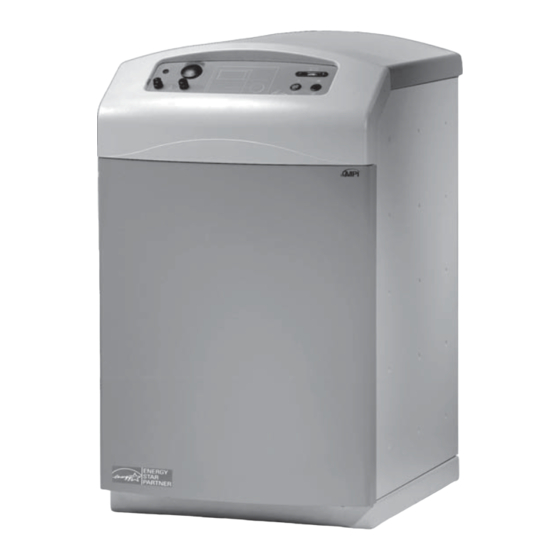
INSTALLATION AND SERVICE MANUAL
Fully Condensing Oil Fired Application Efficiency, Up to 95% efficient
"The availability of these manuals and instructions is not to be construed or interpreted as MPI's approval, consent, or
authorization for any third party to install, repair, or advise on any actions taken on or with the MPI products described therein."
Monitor Products, Inc. reserves the right to make changes without notice
M
ONITOR
M
P
ONITOR
P.O. Box 3408 • Princeton, NJ 08543
www.monitorproducts.com
Revised January 21, 2010
As part of its policy of continuous product improvement,
FCX
, I
RODUCTS
NC
.
1
www.monitorproducts.com
Advertisement
Table of Contents

Related Manuals for MPI FCX

Summary of Contents for MPI FCX
- Page 1 MPI products described therein.” Revised January 21, 2010 As part of its policy of continuous product improvement, Monitor Products, Inc. reserves the right to make changes without notice www.monitorproducts.com...
-
Page 2: Table Of Contents
1 - PRODUCT DESCRIPTION Standard options available from Monitor include: Model FCX oil fired boiler utilizes a sealed combustion system • Coaxial balanced flue system components for connection to that operates at a temperature at which the flue products will the boiler to provide venting of the flue products and combustion condense. -
Page 3: 2-Designation Of Components
INTRODUCTION 2 - DESIGNATION OF COMPONENTS 1) Control Panel 2) Control Panel Cover 3) Safety Pressure Relief Valve 4) Condenser 5) Manual Mixing Valve 6) Combustion Product Pressure Test Point 7) Condenser Inspection Port 8) Condensate Drain View from above 9) Drain Cock Front View 10)Burner Air Inlet Pipe... -
Page 4: 4-Product Standard Ratings
Location and routing of water lines is, of • Remove the front panel attachment screws (P), then pull the course, a significant part of the choice. While Model FCX can be front panel (J) outward towards you at the top to free it from installed in an enclosure such as a closet, ventilation or other the attachment clips. -
Page 5: Flue Connections And Routing
Since the FCX is a condensing boiler, flue products exiting the unit are relatively low temperature, typically from 120 - 212 ° F (49 - 100 ° C), and saturated with humidity. - Page 6 15 and 16 or as dictated by local codes. • Do not place the flue terminal less than 6.56 ft. (2 m) from Option: Straight Horizontal Flue Kit a ventilation hole or opening in a building. NOTE: This is an FCX INSTALLATION AND SERVICE MANUAL...
- Page 7 INSTALLATION Angled Balanced Flue Configuration Fig. 18 Fig. 16 Options: Condensate Tee 3 Concentric extensions 2 45 deg concentric elbows 1 concentric vertical terminal 1 sleeve tile roof flange 1 roof plate Adjustable supports as needed 1 ft minimum above max. snow level Option: Angled Horizontal Flue Kit max L = L1 + 1.64 ft (0.5m) + L2 + 1.64 ft (0.5m) + L3 +...
-
Page 8: Alternative Flue Connections
2210 4.33” (110) propellants, household cleaning products, etc. The FCX boiler is a condensing boiler, which means that the Should be used on the end of 110 mm piping run combustion products from the appliance are discharged at low temperature (120° to 212°F) and saturated with humidity. - Page 9 16.4 feet and the Beckett be used on lengths of 15 to a maximum of 36 feet. 45 degree Polypropylene Elbows The Beckett NX burner adapted for use on the FCX must have Fig. 31 the following specifications: The oil line heater is standard with the burner.
-
Page 10: Condensate Drain Connection
Water circuit connections are made in the back of the unit utilizing the four 1" male pipe thread couplings provided or using other adapters provided. The FCX can be connected to various comfort heating water systems as well as to a domestic hot water heating system if desired, observing that: •Water circulating pumps provided in the various circuits must... - Page 11 INSTALLATION Various typical water circuits are Boiler illustrated below : Pressure gauge Connection to a single heating circuit C1 = Radiator circuit, Baseboards, Radiant Panels Fig. 35 or Fancoils VM1 1 circuit mixer valve Dc1 1 circuit heating outlet Rc1 1 circuit heating return Boiler Connection to a heating circuit with...
-
Page 12: Electrical Connections
24 volt, NEC class 2 for connection to a room thermostat. C. Do not use the internal transformer to power any external system components such as a zone valve. FCX INSTALLATION AND SERVICE MANUAL... -
Page 13: Fuel Oil Supply Connections
INSTALLATION - START UP AND OPERATION UPPER LEFT REAR CORNER OF UNIT (Facing rear of There are three 7/8" holes in the right rear of the unit. Mount unit) a Listed 2 x 4 inch, “HandiBox” type junction box vertically over the lower left hole (facing the rear of the unit) in such Fig. -
Page 14: Adjusting The Oil Burner
To gain access to the inside of the unit, first remove the control panel cover by grasping it on both sides and pulling caps as the valve handle. FCX INSTALLATION AND SERVICE MANUAL... -
Page 15: Cleaning The Boiler Shell
MAINTENANCE 3 - BURNER MAINTENANCE 1 - CLEANING THE BOILER SHELL • Remove the screws (B) from the cast-iron boiler shell Once adjusted properly, regular maintenance of the oil burner cover (C) is not generally required. A routine examination of the burner •... -
Page 16: Combustion Product Flue
This can be prevented if the water temperature control is turned to a System load: Radiant, high temperature, DHW. Total BTU requirement lower temperature, the three way valve is readjusted FCX INSTALLATION AND SERVICE MANUAL... -
Page 17: Monitor Products, Inc. ("Mpi") Limited
4) Replacement parts beyond the balance of the original warranty period. REMEDY: If within the applicable warranty period, any pro-duct(s) As part of its policy of continuous product improvement, Monitor Products, Inc. reserves the right to make changes without notice PART NO. 3000 COPYRIGHT © 2007 MONITOR PRODUCTS, INC. -
Page 18: Fcx Parts Breakdown
PARTS BREAKDOWN V I I P A R T S B R E A K D O W N FCX INSTALLATION AND SERVICE MANUAL... - Page 19 FIXING PIECE FOR THE COVER 2317 SEALING AFM34D 30X21X3 (MALE) 2377L HEATING RETURN 1. CIRCUIT LONG BOLT (PVC) 2378 HEATING FLOW 2. CIRCUIT BAFFLE PLATE F400-F E/FEA-FCX 2318 SEALING ON CONDENSER FLANGE (250X200X1,5) 2379 HEATING FLOW DISK FOR ISOLATION (KERLANE) 2380 BOILER SHELL RETURN...
- Page 20 UPPER FASTENER FOR THE RELAY 2351 SAFETY THERMOSTAT 110 CAP 2356 FUSE 6.3AMP 5X20 1,5M TG400 2358 WIRING FOR FCX 2352 SAFETY THERMOSTAT 120 CAP 1,5M TG400 2359 ELECTR. CONTROL BOX + CABLE * NOT SHOWN ON THE DRAWING FCX INSTALLATION AND SERVICE MANUAL...
-
Page 21: Heat Wise Burner
HEAT WISE BURNER V I I I H E A T W I S E B U R N E R Heat Wise, Inc. 1528 Rocky Point Road Middle Island, NY 11953 LIMITED WARRANTIES FOR OIL AND GAS BURNERS, MADE BY HEAT WISE AND USED IN INSTALLATIONS HEAT WISE, INC. -
Page 22: Operating Instructions
1528 Rocky Point Rd, Middle Island, NY 11953 Note: This particular manual is prepared for the FCX boiler. The burner has been set and test fired to achieve optimum performance. Readjustments, increasing or decreasing pump pressure or nozzle size changes will change the long-term performance. - Page 23 HEAT WISE BURNER 2. WIRING THE BURNER 2.1 Follow the wiring diagram shown in Fig. 2. All the wiring should conform to the National Electric Code (NEC) or the legally authorized code governing your locality. When wiring, be sure that the electric power take-off is connected to a permanently live circuit.
-
Page 24: Servicing The Burner
PSI. This pressure is necessary to get the desired oil flow to local codes. Also, some installations may require an Oil maximize the nozzle output capacity for the FCX. Do not Safety Valve (refer to local codes). exceed 175 PSI. - Page 25 HEAT WISE BURNER Use 3 mm Allen key to remove flame tube loosening set screws on both sides Pull out the flame tube and take precautions to ensure “O” ring is not damaged or lost. - 39 - Use a 4 mm Allen key to loosen the retention head.
-
Page 26: Wiring Diagram
Pump seals including the shaft and gasket areas. *1 The return oil line in a two-pipe system must always be in oil FCX INSTALLATION AND SERVICE MANUAL... - Page 27 Wait 3 minutes and see if motor starts Troubleshooting Flow Chart Reset control for the MPI FCX Boiler Nozzle line heater Okay Does the motor start? Turn power off and connect the power from wiring harness to LI(black) and...
-
Page 28: Parts Breakdown
MPI PART # 2521 Cover Plate (Nozzle Bushing (for Adjustment Assembly) Scale (air) Nozzle Line Screws) 11887301 11887801 11918902 11847901 MPI PART # 2548 MPI PART # 2513 MPI PART # 2519 MPI PART # 2512 FCX INSTALLATION AND SERVICE MANUAL... - Page 29 HEAT WISE BURNER Weiland Plug (Female) Flange Motor Capacitor Gasket – Housing 11811601 11558608 D82132-1 11854401 MPI PART # 2501 MPI PART # 2518 MPI PART # 2547 MPI PART # 2507 Weiland Plug (Male) Suntec Pump Bushing Flange Gasket 11558500 A2VA7116 11847901...
- Page 30 To reset from restricted mode: Press and hold the reset button for 30 draft and reduce oil after-drip related problems. seconds. When the LED flashes twice, the device has reset. FCX INSTALLATION AND SERVICE MANUAL...
-
Page 31: Honeywell Controls
HONEYWELL CONTROL SPECIFICATIONS Current: 100 mA plus burner motor, valve and ignitor loads. Frequency: 60 Hz. Models: Outputs: Table 1 lists the major features and the applicable wiring Relay Contacts: diagram numbers for the R7184. Burner: 120 Vac, 10 full load amperes (FLA), 60 locked rotor Timing: amperes (LRA). - Page 32 OPTIONAL FEATURE ON SELECT MODELS. VALVE MAY BE ADDED AS SHOWN. Fig. 5. Typical wiring diagram for line voltage Aquastat® Fig. 3. Wiring for typical oil-fired boiler. thermostat and R7184 for an oil burner system. FCX INSTALLATION AND SERVICE MANUAL...
- Page 33 HONEYWELL CONTROL TROUBLESHOOTING AND MAINTENANCE IMPORTANT: Due to the potential hazard of line voltage, only a trained, experienced service technician should perform the troubleshooting procedure. This control contains no field-serviceable parts. Do not attempt to take it apart. Replace entire control if operation is not as described. To completely troubleshoot an oil burner installation, check the burner and oil primary control for proper operation and condition.
- Page 34 Voltage should be 120 Vac. or connections are shorted. Go to step 4. 3. Check indicator light with burner off, no call Indicator light is off. Go to step 5. for heat (no flame). FCX INSTALLATION AND SERVICE MANUAL...
- Page 35 HONEYWELL CONTROL Procedure Status Corrective Actions 4. Shield cad cell from external Indicator light turns off. Eliminate external light source or permanently shield cad cell. light. Indicator light stays on. Replace cad cell with new cad cell and recheck. • If indicator light does not turn off, remove cad cell leadwires from R7184 and recheck.
- Page 36 (See Fig. 2.) help establish draft and reduce oil after-drip related problems. FCX INSTALLATION AND SERVICE MANUAL...
- Page 37 HONEYWELL CONTROL Disable Function Valve-on Delay: 15 seconds. Burner motor-off Delay: 0, 2, 4 or 6 minutes. Field selectable Pressing and holding the reset button will disable all functions using dual inline programmable (DIP) switch positions 1 and 2. until the button is released. The R7184 will restart at the beginning Select models have 0.5, 2, 4, or eight minute delays.
- Page 38 Fig. 4. Alarm terminals. Press the two buttons on the top of Make sure the combustion chamber is free of oil and/or oil the terminal, insert wires, and release buttons. vapor before starting system. FCX INSTALLATION AND SERVICE MANUAL...
- Page 39 HONEYWELL CONTROL POWER SUPPLY. PROVIDE DISCONNECT MEANS AND OVERLOAD PROTECTION AS REQUIRED. OPTIONAL FEATURE ON SELECT MODELS. REFER TO DEVICE LABEL FOR WIRE COLOR CODE. VALVE IS OPTIONAL ON SPECIFIC MODELS. SEE FIG. 2. ENVIRACOM™ TERMINAL 3 IS ALSO THE FIRST THERMOSTAT TERMINAL.
- Page 40 See Table 3 for equivalent cad cell resistance and Fig. 11 for an Fig. 9. Typical wiring diagram for24 Vac thermostat and R7184 example of the cad cell resistance reading. for valve-on delay/burner motor off oil burner system. FCX INSTALLATION AND SERVICE MANUAL...
- Page 41 HONEYWELL CONTROL Table 2. Switch Settings and Delays. Delay Timings DIP Switch Settings Valve-On Delay Burner Motor-Off S-3 Enable/ (seconds) Delay (minutes) Disable R7184U R7184P S-1 S-2 R7184U R7184P — X Don’t Care. Specific models may have different timings. Be sure to check device label.
- Page 42 • If indicator light does not turn off, remove cad cell leadwires from light. R7184 and recheck. • If indicator light turns off, replace cad cell bracke assembly. Refer to TRADELINE® Catalog for bracket part numbers. • If indicator light does not turn off, replace controller. FCX INSTALLATION AND SERVICE MANUAL...
- Page 43 HONEYWELL CONTROL Corrective Actions Procedure Status 5. On applications with “valve-on Indicator light is on. • If flame is present, replace valve. delay”, verify that oil valve is closed during the .valve-on delay. period byopening view port and verifying that no flame is present during 15- second.valve-on delay..
-
Page 44: Suntec Pump
IMPORTANT INFORMATION Long or oversized inlet lines PSI on inlet line or return line at the pump. A Pressure greater may require the pump to operate dry during initial bleeding than 10 PSI may cause damage to the shaft seal. FCX INSTALLATION AND SERVICE MANUAL... - Page 45 SUNTEC PUMP ONE-PIPE SYSTEM • MODEL A IDENTIFICATION EXAMPLE Strainer PUMP Series Model Air vent USAGE number L=H+R IDETIFICATION Fill pipe 7112 A1VA Fuel unit Rotation & Nozzle Location Aux filter Shut-off Max. nozzle Max. nozzle valve Maximum one MODEL capacity (GPH) RPM tank MODEL...
-
Page 46: Bs Indirect Storage Tank
BS performance with MZ 25 Max heat transfer kW - Btu/h 23,3-79500 on all tanks Minimum primary water flow m3/h Primary heat exchanger pressure drop mbar Reheating time to 60°C Continuous domestic water flow l/min 11,2 11,2 11,2 11,2 FCX INSTALLATION AND SERVICE MANUAL... - Page 47 1 hour at 40°C must not be removed or plugged - storage 65°C litres 1067 1098 1169 1332 BS performance with FCX Pressure relief valve must be manually operated at least once a year. Max heat transfer kW - Btu/h 22,3 22,3 22,3...
- Page 48 MPI shall jurisdiction to jurisdiction. repair or replace, at its option, the defective product(s) or Monitor Products, Inc., P. O. Box 3408, Princeton, NJ 08543 part(s) and return it to the consumer. (732) 329-0900 PROCEDURE FOR OBTAINING PERFORMANCE UNDER “As part of its policy of continuous product improvement,...
Need help?
Do you have a question about the FCX and is the answer not in the manual?
Questions and answers