Table of Contents
Advertisement
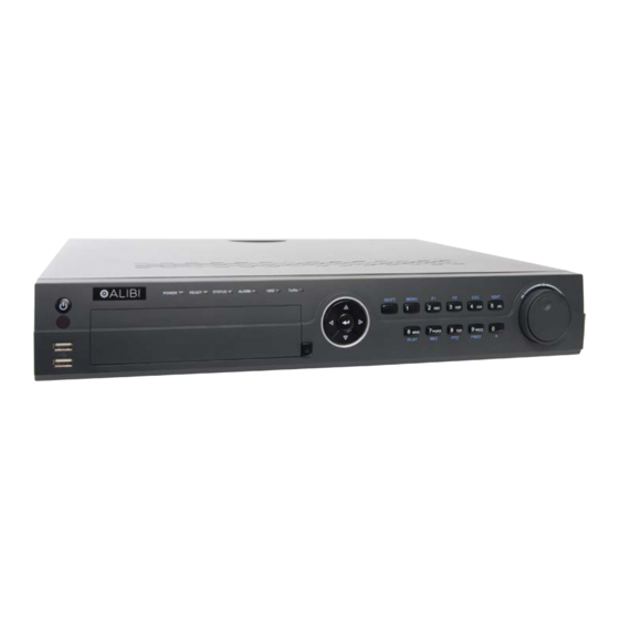
ALI-NVR5000P Series
Embedded Network Video Recorder
User Manual
Products: ALI-NVR5016P, ALI-NVR5032P
ALI-NVR5000P Series Network Video Recorder
PLEASE READ THIS MANUAL BEFORE USING YOUR SYSTEM, and always follow the instructions for safety
and proper use. Save this manual for future reference.
ALI-NVR5016P_SM
7/17/14
Advertisement
Table of Contents

Related Manuals for ALIBI ALI-NVR5000P Series


Summary of Contents for ALIBI ALI-NVR5000P Series
-
Page 1: User Manual
ALI-NVR5000P Series Embedded Network Video Recorder User Manual Products: ALI-NVR5016P, ALI-NVR5032P ALI-NVR5000P Series Network Video Recorder PLEASE READ THIS MANUAL BEFORE USING YOUR SYSTEM, and always follow the instructions for safety and proper use. Save this manual for future reference. ALI-NVR5016P_SM... -
Page 2: Legal Notice
Alibi and the Alibi logo are trademarks of Observint. Microsoft, Windows, and Internet Explorer are either registered trademarks or trademarks of Microsoft Corporation in the United States and/or other countries. -
Page 3: Regulatory Information
SAFETY INSTRUCTIONS Regulatory information FCC information FCC compliance: This equipment has been tested and found to comply with the limits for a digital device, pursuant to part 15 of the FCC Rules. These limits are designed to provide reasonable protection against harmful interference when the equipment is operated in a commercial environment. - Page 4 Install the unit away from heat sources such as radiators, heat registers and stoves. • Installation of the unit near consumer electronics devices, such as stereo receiver/amplifiers and televisions, is permitted as • long as the air surrounding the terminal does not exceed the above mentioned temperature range. Handle hard disk drives with care.
-
Page 5: Table Of Contents
TABLE OF CONTENTS Table of Contents SECTION 1 Systems Overview ..............1 1.1 NVR Controls, connectors and indicators . - Page 6 TABLE OF CONTENTS 2.10 Configuring Exception Alarms ............44 2.11 Setting sensor alarms .
- Page 7 TABLE OF CONTENTS 6.1.6 Configuring HDD Group for Recording ..........83 6.1.7 Files Protection .
- Page 8 TABLE OF CONTENTS SECTION 9 System Maintenance ............. . 132 9.1 System Information .
-
Page 9: Systems Overview
SECTION 1: SYSTEM OVERVIEW SECTION 1 Systems Overview Congratulations on purchasing your new Embedded NVR security system! Your system includes the following key features: General Each channel supports dual-stream video. • Up to 16 network cameras (ALI-NVR5016P) or 32 network cameras (ALI-NVR5032P) •... - Page 10 SECTION 1: SYSTEM OVERVIEW Tag marker insertions, search and playback by tags. • Lock/unlocking video files. • Searching and playing back record files by channel number, recording type, start time, end time, etc. • Motion analysis for the selected area in the video. •...
-
Page 11: Nvr Controls, Connectors And Indicators
SECTION 1: SYSTEM OVERVIEW Auto/manual port mapping by UPnP™. • Remote web browser access by HTTPS ensures high security. • Remote reverse playback via RTSP. • Support accessing by platform via ONVIF. • Remote search, playback, download, locking and unlocking of the record files, and support downloading files broken transfer •... - Page 12 SECTION 1: SYSTEM OVERVIEW Name Function / Description POWER Turns green when NVR is powered up. Status Indicators READY The indicator is green when the device is running normally. The light is green when the IR remote control is enabled; STATUS The light is red when the function of the composite keys (SHIFT) are used;...
- Page 13 SECTION 1: SYSTEM OVERVIEW Name Function / Description Enter numeral “5”; Enter letters “JKL”; 5/JKL/EDIT Delete characters before cursor; Check the checkbox and select the ON/OFF switch; Start/stop record clipping in playback. Enter numeral “6”; 6/MNO/PLAY Enter letters “MNO”; Playback, for direct access to playback interface. Enter numeral “7”;...
- Page 14 SECTION 1: SYSTEM OVERVIEW Item Description CVBS - BNC connector for video output VGA - DB15 connector for VGA compatible monitor. Supports 1920 × 1080p @ 60 Hz, 1600 × 1200 @ 60 Hz, VIDEO OUT 1280 × 1024 @ 60 Hz, 1280 × 720 @ 60 Hz/, 1024 × 768 @ 60 Hz (CVBS, VGA, HDMI) HDMI - HDMI connector for an HDMI compatible monitor.
-
Page 15: Remote Control
SECTION 1: SYSTEM OVERVIEW 1.1.1 Remote control The enter key on the remote control or the front panel has the same function as a mouse left click. The IR Range of the remote control is 10 meters. The buttons on the remote control correspond with the buttons on the front panel. Item Name Function... -
Page 16: Mouse Control
SECTION 1: SYSTEM OVERVIEW Item Name Function Enter the PTZ Control mode (if applicable). PTZ button In the PTZ Control mode, it is used to adjust the iris of the PTZ camera. Return to the previous menu. ESC button Press for Arming/disarming the device in Live View mode. RESERVED Reserved for future usage. -
Page 17: Soft Keyboard
SECTION 1: SYSTEM OVERVIEW 1.1.3 Soft keyboard One of two on-screen keyboards appears when you click in a field that accepts a entry, such as a password or name or a numerical value. A third keyboard which includes symbols can also be opened while in the numeric keyboard. The alphanumeric keyboard is shown in the following picture. -
Page 18: Installing The System
SECTION 2: INSTALLING THE SYSTEM SECTION 2 Installing the System 2.1 Getting Started: Unpacking the Equipment What’s in the box Your system includes: ALI-NVR5000P series NVR • Remote Control • USB mouse • 6 foot Ethernet cable • 6 foot HDMI cable •... -
Page 19: Nvr Installation General Guidelines
SECTION 2: INSTALLING THE SYSTEM 2.2 NVR installation general guidelines 2.2.1 Installing an HDD in the NVR If you purchased your NVR without an internal HDD, you must install one for the NVR to function properly. Follow the procedure In “APPENDIX C HDD Installation” on page 122. If your HDD has an HDD, skip this procedure and continue installing the system with step “2.2.2 NVR Placement”... -
Page 20: Connecting Alarm Devices To The Nvr
SECTION 2: INSTALLING THE SYSTEM If you are using Cat 5e or Cat 6 copper (Ethernet) cable to connect your cameras to the NVR, or other cameras to the LAN, the cable distance from the NVR (or switch on the LAN) should not exceed 330 feet (100 meters). If a longer cable run is required, the use of an active hardware device such as a repeater or switch is necessary. -
Page 21: Install A Monitor, Mouse, Power
SECTION 2: INSTALLING THE SYSTEM 2. Remove the NVR top cover. See “APPENDIX C HDD Installation” on page 167 for instructions. 3. Locate the jumper associated with the alarm output you are using for an AC load alarm, then remove it. Save the jumper for use later, if needed. -
Page 22: Connecting It Together - Initial System Setup
NVR (HDMI or VGA). 2.5.1 Using the Wizard for basic configuration setup 1. Power on the NVR. Normally, an Alibi logo splash screen appears within 2 minutes. A secondary flash screen will appear showing the status of the HDDs installed in the NVR. - Page 23 SECTION 2: INSTALLING THE SYSTEM After the Alibi splash screen appears (see above), the NVR will check the status of HDDs installed within the chassis, and show the show icons on the screen indicating their status. A green check mark on the icon indicates that the associated HDD is operating normally.
- Page 24 SECTION 2: INSTALLING THE SYSTEM 3. Enter the admin password in the appropriate field. To do that, click inside the Admin Password field to open the virtual keyboard. Click the appropriate keys (icons) to enter the password, then click the Enter icon. The default admin password is 1111.
- Page 25 SECTION 2: INSTALLING THE SYSTEM 4. Click the Next button to open the date and time settings window. 5. In the date and time setup window, click the field you want to change, then use the drop-down list or setup aid to select the appropriate values.
- Page 26 SECTION 2: INSTALLING THE SYSTEM Generally, it is preferable to setup the NVR with a fixed network settings, if possible, to assure the NVR has an unchanging IP address for remote login. To enable fixed network settings, un-check the Enable DHCP box, then edit the appropriate fields to change the settings.
- Page 27 SECTION 2: INSTALLING THE SYSTEM 8. In the next window, the Wizard will search the LAN to find compatible cameras to add to the system. With the ALI-NVR5016P, you can monitor up to 16 IP cameras total (the sum of those attached to ports in the integrated 16-port Ethernet switch plus those added from the LAN the NVR is attached to).
- Page 28 SECTION 2: INSTALLING THE SYSTEM Click the star for Continuous or Motion Detection, click Yes in the Attention pop-up window, and then click OK to save the settings. The Wizard will close and the NVR will present the Live View display. For more information about the Live View display, see “SECTION 4 Live View Interface”...
-
Page 29: Access The Menu System
SECTION 2: INSTALLING THE SYSTEM Live View display after camera adjustments 2.6 Access the Menu system After the initial setup of your NVR using the Wizard, the Menus interface enables you to refine your configuration settings and expand the functionality of the system. To use most menus, the user must log into the NVR system, either locally or remotely, with administrative privileges. -
Page 30: Customize Camera Configurations
SECTION 2: INSTALLING THE SYSTEM If ID Authentication is not disabled (see the Menu | Configuration | General settings), a login window will open. In the Login window, select a User Name with administrative privileges, enter its password, then click OK. NOTE: A window of Menu icons will open. -
Page 31: Camera Osd Setup
SECTION 2: INSTALLING THE SYSTEM 2.7.1 Camera OSD setup You can configure the OSD (On-Screen Display) settings for the camera, including date, time, day of week, camera name, etc. 1. Click OSD in the left frame to open the OSD submenu. 2. In the Camera field drop down list, select the camera you want to configure. In the example shown, IP Camera 1 is selected. 3. -
Page 32: Camera Ptz Setup
SECTION 2: INSTALLING THE SYSTEM 2. In the Camera field drop down list, select the camera you want to configure. In the example shown, IP Camera 1 is selected. 3. Drag the Brightness, Contrast, Saturation and Hue adjustment markers left or right to perfect the image from the camera. - Page 33 SECTION 2: INSTALLING THE SYSTEM 2. In the Camera field drop down list, select the camera you want to configure. In the example shown, IP Camera 1 is selected. 3. Check or un-check the box to Enable Motion Detection. If you checked the box, the grid shown over the video image is the area where motion will be detected.
- Page 34 SECTION 2: INSTALLING THE SYSTEM a. Select the other channels that should trigger recording on this channel, then click Apply to save your settings. b. Click the Arming Schedule tab. In this tab, you can define up to eight periods for each day. The periods must not overlap.
-
Page 35: Camera Privacy Mask Setup
SECTION 2: INSTALLING THE SYSTEM Select the actions you want to occur, then click Apply to save your settings, and OK to return to the Motion menu. The Notify Surveillance Center and Send Email options require additional network settings. 5. In the Motion menu, click Apply to save your settings for this camera. 6. -
Page 36: Camera Video Tampering Setup
SECTION 2: INSTALLING THE SYSTEM 2. In the Camera field drop down list, select the camera you want to configure. In the example shown, IP Camera 1 is selected. 3. Check or un-check the box to Enable Privacy Mask. If you checked the box, drag a rectangle across the area of the video that you want to block. - Page 37 SECTION 2: INSTALLING THE SYSTEM a. In the Arming Schedule tab, you can define up to eight periods for each day. The periods must not overlap. b. Click the down arrow in the Mon field (see above) to setup the schedule for a different day, and/or click Copy to copy the Arming Schedule you setup in the window to other days of the week.
-
Page 38: Camera Video Loss Setup
SECTION 2: INSTALLING THE SYSTEM g. Repeat sub-steps 2 through 4 above for each camera managed by the NVR, if necessary. Test your settings during broad conditions to ensure that your tamper-proof settings trigger an action. You may need to return to NOTE this menu later to adjust the Sensitivity slider to ensure the feature is working properly. - Page 39 SECTION 2: INSTALLING THE SYSTEM b. In the Arming Schedule tab, you can define up to eight periods for each day. The periods must not overlap. c. Click the down arrow in the Mon field (see above) to setup the schedule for a different day, and/or click Copy to copy the Arming Schedule you setup in the window to other days of the week.
-
Page 40: Camera Vca Setup
SECTION 2: INSTALLING THE SYSTEM 5. Repeat sub-steps 2 through 4 above for each camera managed by the NVR, if necessary. 2.7.8 Camera VCA setup VCA (Video Content Analysis) is not supported at this time. 2.8 Adding cameras manually IP cameras can connect to the NVR either through the 16-port integrated Ethernet switch on the back panel of the NVR, or through the LAN the NVR is connected to. - Page 41 SECTION 2: INSTALLING THE SYSTEM b. To add cameras on the LAN, scroll to the bottom of the list and find a camera that is not assigned to a channel. In the example below, the camera at IP address 192.168.75.113 is not assigned. c.
- Page 42 SECTION 2: INSTALLING THE SYSTEM If the Status indicates a protocol error, click the entry field on the Protocol line and then select the camera protocol (usually the manufacturer’s name) of the camera you want to add. The Protocol is shown in the camera data discovered during the search.
-
Page 43: Configuring Customized Protocols
SECTION 2: INSTALLING THE SYSTEM Click OK when done to return to the camera menu, and then verify that the status changes to a blue “Play” symbol iii. e. For the camera you added, the Status column should show a blue “Play” symbol icon. Click that icon to verify that a video image is being received properly by the NVR. - Page 44 SECTION 2: INSTALLING THE SYSTEM Before customizing the protocol for the network camera, contact the manufacturer for specific information regarding main stream NOTE and sub-stream setup requirements. Example: The format of the URL is: [Type]://[IP Address of the network camera]:[Port]/[Path]. E.g., rtsp://192.168.1.55:554/ch1/ main/av_stream.
-
Page 45: Configuring Hdd Settings
SECTION 2: INSTALLING THE SYSTEM Path: Set the resource path for the custom protocol. E.g., ch1/main/av_stream. • 2. Click Apply to save the settings, and then click OK to close the menu. After adding the customized protocols, you can select the protocol name listed in the drop down list. -
Page 46: Managing Network Storage
SECTION 2: INSTALLING THE SYSTEM 2.9.2 Managing Network Storage Additional file storage can be added to your NVR using up to 8 NAS disks, or up to 7 NAS disks with 1 IP SAN disk. To configure this storage: 1. Open the HDD Information interface. Go to Menu | HDD | General 2. - Page 47 SECTION 2: INSTALLING THE SYSTEM Click the Search button to search for available NAS disks. iii. Select the NAS disk directory from the list shown, or manually enter the directory in the text field of NetHDD Directory. Click OK to add the NAS disk to your system. For an IP SAN disk: —...
-
Page 48: Configuring The Hdd
SECTION 2: INSTALLING THE SYSTEM Select the IP SAN disk directory from the list shown below. Click OK to add the selected IP SAN disk to your system. If the added NetHDD is uninitialized, select it and click the Init button for initialization. Initializing an storage device erases all data NOTE saved on the disk. - Page 49 SECTION 2: INSTALLING THE SYSTEM 2. Click Advanced to check the storage mode of the HDD. a. In the Mode select field, select either Partition or Group. If you selected Partition, select a camera in the Camera field, then enter the size, in gigabytes, in the Max. Record Capacity field.
-
Page 50: Hdd Detect
SECTION 2: INSTALLING THE SYSTEM 2.9.4 HDD Detect The HDD Detect feature provides two methods of monitoring the HDD: display of S.M.A.R.T. (Self-Monitoring, Analysis and Reporting Technology) data, and Bad Sector Detection. These methods can be used to assure the normal functioning of the disk, and anticipate failures. -
Page 51: Bad Sector Detection
SECTION 2: INSTALLING THE SYSTEM S.M.A.R.T. data provided by each HDD manufacturer is usually different. Refer to the manufacturer’s website for S.M.A.R.T. data NOTE definitions. Bad Sector Detection 1. Open the Bad Sector Detection menu. Go to Menu | System Maintenance | HDD Detect | Bad Sector Detection 2. -
Page 52: Configuring Exception Alarms
SECTION 2: INSTALLING THE SYSTEM Click Pause to temporarily stop the scan, and click Cancel to end the scan. Click Error info to see the detailed damage information. 2.10 Configuring Exception Alarms The NVR monitors for and respond to certain system-related alarm conditions (exception alarms). Monitoring for and response to these exceptions are configurable. -
Page 53: Setting Sensor Alarms
SECTION 2: INSTALLING THE SYSTEM To configure exception alarms: 1. Open the Exception menu. Go to Menu | Configuration | Exceptions 2. On the Exception Type line, open the drop down list and select the exception condition you want to configure. If you select All, all exception conditions will be treated the way you configure the response. - Page 54 SECTION 2: INSTALLING THE SYSTEM 2. Select the Alarm Input tab. 3. Open the Alarm Input No. drop down list and select the alarm input you want to configure. In the example above, Local<-1 is selected. 4. Open the Type drop down list and select the active state of the alarm. Choose either N.O. for normally open, N.C. for normally closed.
- Page 55 SECTION 2: INSTALLING THE SYSTEM 8. Click Apply to save the settings. 9. Click the Arming Schedule tab. In this tab, you can define up to eight periods for each day. The periods must not overlap. 10. Click the down arrow in the Mon field (see above) to setup the schedule for a different day, and/or click Copy to copy the Arming Schedule you setup in the window to other days of the week.
- Page 56 SECTION 2: INSTALLING THE SYSTEM 13. In the Linkage Action menu, select the actions you want to occur when the alarm is active, then click Apply to save the settings. If PTZ cameras are not installed on your system, click OK to return to the Alarm Input menu. 14.
-
Page 57: Setting Alarm Response Actions
SECTION 2: INSTALLING THE SYSTEM a. Click the Copy button at the bottom of the Alarm Input menu. b. Check the boxes for the alarm inputs you want to copy the configuration to. c. Click OK to save your settings. 2.12 Setting alarm response actions Alarm response actions will be activated when an alarm or exception occurs, including Event Hint Display, Full Screen Monitoring, Audible Warning (buzzer), Notify Surveillance Center, Upload Picture to FTP, Trigger Alarm Output and Send Email. - Page 58 SECTION 2: INSTALLING THE SYSTEM 2. Check the Enable Event Hint box. See above. 3. Click the icon to set the type of event to be displayed on the image. 4. Select the type of event you want to be displayed on the image. 5.
-
Page 59: Email Linkage
SECTION 2: INSTALLING THE SYSTEM Full Screen Monitoring When an alarm is triggered, the local monitor (VGA, HDMI or BNC monitor) the video image from the alarming channel configured for full screen monitoring is displayed. If alarms are triggered simultaneously in several channels, their full-screen images will be switched at an interval of 10 seconds (default dwell time). - Page 60 SECTION 2: INSTALLING THE SYSTEM 2. Select an alarm output, set alarm name, then specify a dwell time. 3. Click the Settings icon ( )to open the Schedule menu. 4. In the Arming Schedule, you can define up to eight periods for each day. The periods must not overlap. 5.
- Page 61 SECTION 2: INSTALLING THE SYSTEM 7. Repeat steps 3 - 7 above to configure additional alarm outputs connected to your NVR, if necessary. You can also copy an the alarm input setup you saved to other alarm inputs. To do so: a.
-
Page 62: Startup, Shutdown, Reboot
SECTION 3: STARTUP, SHUTDOWN, REBOOT SECTION 3 Startup, Shutdown, Reboot After the NVR and cameras are installed, the NVR system must be configured to function in the surveillance mode(s) that best serve your needs. This chapter includes the essential steps to get your system running, including configuring the NVR date and time, and setting up the LAN interface, cameras and recording modes. -
Page 63: Rebooting The Nvr
SECTION 3: STARTUP, SHUTDOWN, REBOOT admin NOTE The default User Name with administrative privileges and its associated Password are and 1111. 3. In the Menu window, click the Shutdown icon, then click Shutdown in the pop-up window. 4. Click Yes in the Attention window. 5. -
Page 64: Live View Interface
SECTION 4: LIVE VIEW INTERFACE SECTION 4 Live View Interface The Live View interface is the primary camera viewing and monitoring mode. It can be configured to present video from the cameras configured in the system singularly or in multi mode, or using a “patrol” feature wherein video from each of a select group of cameras is displayed singularly and sequentially, with each camera view shown for a preset duration (dwell). -
Page 65: Front Panel Operation On Live View
SECTION 4: LIVE VIEW INTERFACE Add IP Camera: the shortcut to the IP camera management interface. • Playback: playback the recorded videos for current day. • Aux/Main output switch: the NVR checks the connection of the output interfaces to define the main and auxiliary output •... -
Page 66: Using The Mouse In Live View
SECTION 4: LIVE VIEW INTERFACE 4.1.2 Using the mouse in Live view Table 3. Mouse operation in Live view Name Description Menu Enter the main menu of the system by right clicking the mouse. Single Screen Switch to single full screen by choosing channel number from the drop down list. Multi-screen Select the screen layout from the drop down list. -
Page 67: Live View Status Icons
SECTION 4: LIVE VIEW INTERFACE NOTE In the live view mode of the main output monitor, the menu operation is not available while Aux output mode is enabled. 4.1.4 Live View Status icons In the Live view mode, icons can appear in the upper-right of the screen for each channel, showing the status of the record and alarm in the channel. - Page 68 SECTION 4: LIVE VIEW INTERFACE Zoom selection area Image Settings: Click this icon to open menus for creating customized setting for the brightness, contrast, saturation and hue of the camera image. After making an adjustment on in this menu, the NVR will respond within a few seconds. Click OK when your adjustments are complete.
-
Page 69: Live View Pop-Up Menu
SECTION 4: LIVE VIEW INTERFACE 4.3 Live View pop-up menu Right-clicking the mouse on the desktop opens the pop-up window shown below. Clicking one of the items listed produces the result described below. Menu: Opens the configuration menu window. See “SECTION 6 Record, Playback and Video Backup” on page 72. —... - Page 70 SECTION 4: LIVE VIEW INTERFACE Adjust the settings in the screen as needed: Video Output Interface: Designates the output to configure the settings for. Option includes only VGA/HDMI. — Live View Mode: Designates the display mode (screen split) to be used for Live View. 1 * 1 is a single camera view. —...
-
Page 71: Channel-Zero Encoding
SECTION 4: LIVE VIEW INTERFACE 4. Click the single- or multi-screen select icon for the screen split you prefer. In the example shown above, a 32 screen view is selected. 5. Click a viewing screens, then double-click the camera in the list on the left that you what to show there. When the selection is made, label in the viewing screen changes to the camera channel number. -
Page 72: Ptz Controls
SECTION 5: PTZ CONTROLS SECTION 5 PTZ Controls 5.1 Configuring PTZ settings Follow the procedure to set the parameters for control of a PTZ camera installed in the system. Setup of the PTZ parameters should be done before you control the PTZ camera. This feature is only supported for PTZ capable cameras in the compatible cameras list. See “APPENDIX D NVR Compatible Cameras”... -
Page 73: Setting Ptz Presets, Patrols And Patterns
SECTION 5: PTZ CONTROLS 5.2 Setting PTZ presets, patrols and patterns NOTE The presets, patrols and patterns you configure must be supported by the PTZ protocols. 5.2.1 Customizing Presets Follow the steps to set the Preset location which you want the PTZ camera to point to when an event takes place. 1. -
Page 74: Calling Presets
SECTION 5: PTZ CONTROLS 5.2.2 Calling Presets After creating a preset, you can quickly move the camera to that position by “calling” that preset. Use the PTZ More Settings inter face to call a preset. 1. Open the PTZ settings menu. Go to: Menu | Camera | PTZ | More Settings 2. -
Page 75: Customizing Patrols
SECTION 5: PTZ CONTROLS 5.2.3 Customizing Patrols Patrols can be set to position a PTZ camera to a KeyPoint (Preset number) and hold it there there for a set duration (dwell) before moving on to another KeyPoint (Preset number). To create Preset positions for the camera, see “5.2.1 Customizing Presets” on page 1. -
Page 76: Calling Patrols
SECTION 5: PTZ CONTROLS 6. Repeat the above steps to add more KeyPoints. You can also delete all the key points by clicking the trash icon . Select a KeyPoint, then click button to adjust the order of the KeyPoints. 5.2.4 Calling Patrols Calling a patrol makes the PTZ to move according the predefined patrol path. -
Page 77: Customizing Patterns
SECTION 5: PTZ CONTROLS 5.2.5 Customizing Patterns Patterns can be set by recording the movement of the PTZ. You can call the pattern to make the PTZ movement according to the predefined path. 1. Open the PTZ settings menu. Go to: Menu | Camera | PTZ | More Settings 2. -
Page 78: Calling Patterns
SECTION 5: PTZ CONTROLS 3. Click , then use the mouse to drag the image, or click the eight directional buttons in the control box under the image, to move the PTZ camera. The movement of the camera will be recorded as the pattern. 4. - Page 79 SECTION 5: PTZ CONTROLS PTZ control panel icons ALI-NVR5000P Embedded NVR User Manual...
-
Page 80: Record, Playback And Video Backup
SECTION 6: RECORD, PLAYBACK AND VIDEO BACKUP SECTION 6 Record, Playback and Video Backup After the initial setup of your NVR using the Wizard, the Menus interface enables you to refine your configuration settings and expand the functionality of the system. To use most menus, the user must log into the NVR system, either locally or remotely, with administrative privileges. -
Page 81: Configuring Record Settings
SECTION 6: RECORD, PLAYBACK AND VIDEO BACKUP 6.1 Configuring record settings 6.1.1 Setting camera parameters 1. Enter the Record settings interface to configure the encoding parameters. Go to Menu | Record | Parameters. 2. Select the Record tab page you want to configure. You can configure the stream type, the resolution, and other parameters. Pre-record: The length of time you set to record before the scheduled time or event. -
Page 82: Configuring Record Schedule
SECTION 5: PTZ CONTROLS a. Configure the parameters of the camera. b. Click Apply to save the settings. Capture parameters 5. Open the Capture tab. 6. Configure the Capture parameters. NOTE: The interval is the time period between two capturing actions. You can configure all the parameters on this menu on your demand. - Page 83 SECTION 6: RECORD, PLAYBACK AND VIDEO BACKUP 2. To configure the Record schedule: a. Open the Camera drop-down list to select the camera you want to configure. b. Check the Enable Schedule box. c. Click Edit, or use the graphical method to apply recording modes to hours of the day. If you clicked the Edit button, a record schedule list opens.
- Page 84 SECTION 6: RECORD, PLAYBACK AND VIDEO BACKUP In the Type column, select the type of recording trigger you want to use. “Motion” recording is recording — triggered by some kind of motion detected in the video image. Alarm recording is not supported. Click Apply to save your settings.
- Page 85 Recording triggered by Video Content Analysis* Delete schedule or no recording scheduled Alarm triggered recording is available for only some cameras models supported by the Alibi NVR. Consult your vendor support NOTE organization for more information. NOTE * Video Content Analysis triggered recording is not available at this time.
-
Page 86: Configuring Capture Schedule
SECTION 6: RECORD, PLAYBACK AND VIDEO BACKUP Click Apply to validate the settings. — 3. If the settings can be applied to other camera channels, click Copy. 4. In the Copy menu, click the channels you to which you want to copy the schedule to, then click OK. 6.1.3 Configuring Capture schedule 1. -
Page 87: Configuring Motion Detection Recording
SECTION 6: RECORD, PLAYBACK AND VIDEO BACKUP 2. Configure the Capture schedule as you configured the Record schedule. Refer to “6.1.2 Configuring Record schedule” on page 74. 3. Click Apply to save the configuration. 6.1.4 Configuring Motion Detection Recording Follow the steps to set the motion detection parameters. A motion detection events can trigger several kind of actions by the NVR, including channels to start recording, full screen monitoring, an audio warning, notification sent to the surveillance center, etc. - Page 88 SECTION 6: RECORD, PLAYBACK AND VIDEO BACKUP d. If you want to sense for motion detection in all areas of the video, click Clear All, and then drag a rectangle over the entire video screen. NOTE: The example shown here is for a 3S Vision camera. Other camera brands and models have different methods for designating the motion detection areas.
- Page 89 SECTION 6: RECORD, PLAYBACK AND VIDEO BACKUP h. Click Apply to save the settings. You can also click Copy to copy the Arming Schedule setup in the window to other days of the week. Click the Linkage Action tab. In the Handling tab, you can cause certain actions to occur when motion triggered recording occurs.
-
Page 90: Manual Record
SECTION 6: RECORD, PLAYBACK AND VIDEO BACKUP 6.1.5 Manual record Follow the steps below to begin manual recording. Manual recording, once initiated, requires a manual cancel of the record. The manual recording can occur prior to the scheduled recording. 1. Open the Manual settings menu. Go to Menu | Manual. 2. -
Page 91: Configuring Hdd Group For Recording
SECTION 6: RECORD, PLAYBACK AND VIDEO BACKUP Green “ON” icon means that the channel is configured with a record schedule. NOTE If the NVR is rebooted, manual record operations are canceled. 6.1.6 Configuring HDD Group for Recording You can group the HDDs and save the record files in a specific HDD group. You must have multiple HDDs installed in the system to perform this configuration. -
Page 92: Files Protection
SECTION 6: RECORD, PLAYBACK AND VIDEO BACKUP c. Click Apply and then in the pop-up message box, click Yes to save your settings. d. Click OK to go to the menu window. 7. Repeat the steps above to configure more HDD groups. 6.1.7 Files Protection You can lock the recorded files or set the HDD property to Read-only to protect the record files from being overwritten. -
Page 93: Playback
SECTION 6: RECORD, PLAYBACK AND VIDEO BACKUP Lock icon (shown “Unlocked”) 5. To protect the record files, determine which files you want to protect, and then click the icon in the Lock column to show a “locked” padlock (indicating that the file is locked). Similarly, unlock files by clicking on the “locked” icon to show an “unlocked”... -
Page 94: Playing Back Video By Channel
SECTION 6: RECORD, PLAYBACK AND VIDEO BACKUP Instant playback 6.2.2 Playing back video by channel 1. Open the Playback menu. Go to Menu | Playback. You can also open single channel playback mode by viewing a single channel in Live view mode, then pressing the Play button on the front panel. 2. - Page 95 SECTION 6: RECORD, PLAYBACK AND VIDEO BACKUP 4. To start playback, click the Play button ( u ) in the playback controls panel at the bottom of the screen. Playback controls are shown below. ALI-NVR5000P Embedded NVR User Manual...
- Page 96 SECTION 6: RECORD, PLAYBACK AND VIDEO BACKUP Start/stop default custom Zoom Mute clip Capture Lock management Start/end time of timeline Recorded video clips Playback motion controls Playback timestamp Timeline Playback toolbar icons NOTES:...
-
Page 97: Playing Back By Time
SECTION 6: RECORD, PLAYBACK AND VIDEO BACKUP In the “Recorded video clips” markings, blue marks represent Normal recording, red marks indicate event recording (motion, • alarm, motion | alarm, motion & alarm, VCA). Timeline: Use the mouse to click any point of the timeline bar to locate special frames, and drag the cursor to show the •... -
Page 98: Playback By Event Search
SECTION 6: RECORD, PLAYBACK AND VIDEO BACKUP For the definition of icons in the playback toolbar, see “6.2.2 Playing back video by channel” on page 86. NOTES: In the “Recorded video clips” markings, blue marks represent Normal recording, red marks indicate event recording (motion, •... - Page 99 SECTION 6: RECORD, PLAYBACK AND VIDEO BACKUP 2. Open the drop-down list in the upper-left corner of the screen, then select Event. 3. Open the Type drop down list (in the upper right corner), then select the kind of event you want to search for. In the example above, only Alarm Input and Motion type events are available.
- Page 100 SECTION 6: RECORD, PLAYBACK AND VIDEO BACKUP 5. Click Search. A list of events (channel and time) that occurred during the time frame selected will appear on the right side of the screen. 6. Select an entry in the list (camera channel and the time), then click the Play icon in the playback toolbar to show the video associated with the event.
-
Page 101: Playback By Tag
SECTION 6: RECORD, PLAYBACK AND VIDEO BACKUP 6.2.5 Playback by Tag Video tags provide a convenient way to identify video clips, then find and replay them later. Tags are associated with video clips during playback using the icons in the lower left corner of the screen. 1. - Page 102 SECTION 6: RECORD, PLAYBACK AND VIDEO BACKUP 5. In the pop-up window above, the tag auto theft was keyed in. After entering the tag name, click Enter, then click OK to close the Add Tag window. Tag management 6. Click the icon to open the Tag management window.
- Page 103 SECTION 6: RECORD, PLAYBACK AND VIDEO BACKUP Search for tagged video clips 7. In the Playback interface window, open the drop-down list in the upper-left corner of the screen, then select Tag. 8. Select the camera channels that contain tags you want to search for. 9.
-
Page 104: Smart Playback
SECTION 6: RECORD, PLAYBACK AND VIDEO BACKUP In the Playback window, you can change the Pre-play and Post-play values to see more video around the tag. 6.2.6 Smart Playback The smart playback feature provides an easy way bypass less effective information. When you select Smart playback mode, the system will analyze the video containing the motion or VCA information, mark it with green color and play it in the normal speed while the video without motion will be played in the 16x speed. -
Page 105: Playback Using System Logs
SECTION 6: RECORD, PLAYBACK AND VIDEO BACKUP 6.2.7 Playback using System logs You can play back record file(s) associated with channels after searching system logs. 1. Open the Log Information menu. Go to Menu | Maintenance | Log Information ALI-NVR5000P Embedded NVR User Manual... - Page 106 SECTION 6: RECORD, PLAYBACK AND VIDEO BACKUP 2. Select a Start Time, End Time, Major Type and Minor Type., then click Search. In the example below, the search criterion specified are “All” (Major Type) entries. 3. Find the entry in the search results list that is associated with a Play icon. See the example above. 4.
-
Page 107: Playing Back An External File
SECTION 6: RECORD, PLAYBACK AND VIDEO BACKUP 6.2.8 Playing Back an external file You can playback a file on an external device, such as a video file saved on a backup disk or flash drive. 1. Open the Playback interface. Go to Menu | Playback 2. - Page 108 SECTION 6: RECORD, PLAYBACK AND VIDEO BACKUP 5. Click the Play icon associated with the file you want to play.
-
Page 109: Auxiliary Functions - Playback Frame By Frame
SECTION 6: RECORD, PLAYBACK AND VIDEO BACKUP 6.2.9 Auxiliary Functions - Playback frame by frame Play video files frame by frame, in case of checking image details of the video when abnormal events happen. Using a Mouse Go to Menu | Playback Playback a file. During playback, click the button tt until the speed changes to Single. One click on the playback screen advances playback to the next frame forward. -
Page 110: Digital Zoom
SECTION 6: RECORD, PLAYBACK AND VIDEO BACKUP 3. Double-click the date on the calendar to select the day when video was recorded. On the calendar, days when video was recorded for the cameras selected is marked in blue. The day selected is bordered in yellow. Date selected Video recorded (yellow border) -
Page 111: Backing Up Record Files - Export
SECTION 6: RECORD, PLAYBACK AND VIDEO BACKUP Zoom selection area 3. Right-click on the image to exit the digital zoom mode. 6.3 Backing up Record Files - Export 6.3.1 Quick Export The Quick Export feature allows you to easily export (backup to an external device) video clips recorded over a 24 hours period from up to four selected camera channels. - Page 112 SECTION 6: RECORD, PLAYBACK AND VIDEO BACKUP 3. Check the boxes for the camera channels you want to back up. 4. Select the Start Time and End Time of the period when the video clips of interest were recorded. To change the time, click on the field, then select the target date or time from the pop-up menu.
-
Page 113: Export By Video Search
SECTION 6: RECORD, PLAYBACK AND VIDEO BACKUP Note: The Player utility player.exe will be exported automatically during video file export. 6.3.2 Export by video search The Export by video search feature allows you to export specific video clips. The export operation writes the selected file(s) to an USB device. - Page 114 SECTION 6: RECORD, PLAYBACK AND VIDEO BACKUP 4. Select the Start Time and End Time of the period when the video clips of interest were recorded. To change the time, click on the field, then select the target date or time from the pop-up menu. 5.
- Page 115 SECTION 6: RECORD, PLAYBACK AND VIDEO BACKUP 8. In the Export window, select the directory where you want to copy the files, or create a New Folder. 9. Click the Export button to start the Export. The Export window will list the files that were transferred. Allow the process to finish before continuing.
-
Page 116: Export By Event Search
SECTION 6: RECORD, PLAYBACK AND VIDEO BACKUP Note: The Player utility player.exe will be exported automatically during video file export. 6.3.3 Export by Event Search Video recordings triggered my Events, such as motion detection, can be searched for and exported to a USB storage device such as a USB flash drive or USB disk drive, or USB optical drive. - Page 117 SECTION 6: RECORD, PLAYBACK AND VIDEO BACKUP 5. Click Search to list the video clips recorded during the selected time span. 6. To watch a video clip in the Motion (search result) list, click (highlight) the clip you want to watch, click Details, then in the Event Details window, click the icon in the Play column of the file.
-
Page 118: Exporting Video Clips During Playback
SECTION 6: RECORD, PLAYBACK AND VIDEO BACKUP external storage device. If your USB device is not shown in the Device Name field, click the Refresh button. NOTE: Some USB devices types include the New Folder and Format options, other types include only an Erase option. 8. - Page 119 SECTION 6: RECORD, PLAYBACK AND VIDEO BACKUP 1. Attach an USB storage device, such as a USB flash drive or USB disk drive or USB optical drive, to the NVR USB port. 2. Playback a video file. Clip (Start clipping) icon 3.
- Page 120 SECTION 6: RECORD, PLAYBACK AND VIDEO BACKUP Clip (Stop clipping) icon 5. Right click anywhere in the video window. The Attention pop-up window shown below will appear. 6. Click Yes to save the video clip you marked. 7. In the Export window, select the directory where you want to save the file if available, or just click Export, then click Quick Export.
- Page 121 SECTION 6: RECORD, PLAYBACK AND VIDEO BACKUP 8. In the Export window, select the directory where you want to copy the files, or create a New Folder. 9. Click the Export button to start the Export. The Export window will list the files that were transferred. Allow the operation to finish before continuing.
- Page 122 SECTION 6: RECORD, PLAYBACK AND VIDEO BACKUP Note: The Player utility player.exe will be exported automatically during video file export.
-
Page 123: Managing User Accounts
SECTION 7: MANAGING USER ACCOUNTS SECTION 7 Managing User Accounts User accounts are created to control access to the system both at the NVR and when logging into the NVR from a remote computer. Each account has a User Name, Password, and a selection of permissions granted to the user. By default, one user, named “admin”, is provided. - Page 124 SECTION 7: MANAGING USER ACCOUNTS 3. Enter the information for new user, including User Name, Password, Level and User’s MAC Address. Set the user Level to Operator or Guest. Different Levels have different operating permission. — Operator: The Operator user level has permission of Two-way Audio in Remote Configuration and all operating permission in Camera Configuration by default.
- Page 125 SECTION 7: MANAGING USER ACCOUNTS 6. Set the operating permission of Local Configuration, Remote Configuration and Camera Configuration for the user. Local Configuration options: Local Log Search: Searching and viewing logs and system information of NVR. — Local Parameters Settings: Configuring parameters, restoring factory default parameters and importing/exporting —...
- Page 126 SECTION 7: MANAGING USER ACCOUNTS Remote Log Search: Remotely viewing logs that are saved on the NVR. — Remote Parameters Settings: Remotely configuring parameters, restoring factory default parameters and — importing/exporting configuration files. Remote Camera Management: Remote adding, deleting and editing of the IP cameras. —...
-
Page 127: Deleting A User Account
SECTION 7: MANAGING USER ACCOUNTS NOTE Only the admin user account has permission to restore the NVR to factory default settings. 8. Select the IP Camera(s) the user will have access to. 9. Click Apply to save your settings, then click OK to return to the User menu. 7.2 Deleting a user account 1. -
Page 128: Edit Admin User
SECTION 7: MANAGING USER ACCOUNTS 2. Select the user to be edited from the list (see the User Management window above). 3. Click the Edit icon to open the Edit User interface. Note: The user name admin can also be changed. 4. - Page 129 SECTION 7: MANAGING USER ACCOUNTS admin user Edit User menu ALI-NVR5000P Embedded NVR User Manual...
-
Page 130: Network Settings
SECTION 8: NETWORK SETTINGS SECTION 8 Network Settings 8.1 Configuring General Settings Network settings must be properly configured before you connect the NVR to cameras on network, or access it remotely. 1. Open the Network Settings menu. Go to Menu | Configuration | Network 2. -
Page 131: Configuring Advanced Settings
SECTION 8: NETWORK SETTINGS 8.2 Configuring Advanced Settings 8.2.1 Configuring DDNS If your NVR is set to use PPPoE as its default network connection, you may set Dynamic DNS (DDNS) to be used for network access. Registration with your ISP is required before configuring the system to use DDNS. 1. - Page 132 SECTION 8: NETWORK SETTINGS Enter Server Address for DynDNS (i.e. members.dyndns.org). In the NVR Domain Name text field, enter the domain obtained from the DynDNS website. iii. Enter the User Name and Password registered in the DynDNS website. NO-IP: Enter the account information in the corresponding fields. Refer to the DynDNS settings. —...
-
Page 133: Configuring Ntp Server
SECTION 8: NETWORK SETTINGS In the NVR Domain Name text field, enter the domain obtained from the NO-IP website (www.no-ip.com). 8.2.2 Configuring NTP Server A Network Time Protocol (NTP) Server can be configured on your NVR to ensure the accuracy of system date/time. 1. -
Page 134: Configuring Remote Alarm Host
SECTION 8: NETWORK SETTINGS 8.2.3 Configuring Remote Alarm Host With a remote alarm host configured, the NVR will send the alarm event or exception message to the host when an alarm is triggered. The remote alarm host must have the Network Video Surveillance software installed. 1. -
Page 135: Configuring Rtsp
SECTION 8: NETWORK SETTINGS 3. Set the Multicast IP address. When adding a device to the Network Video Surveillance Software, the multicast address must be the same as the NVR’s multicast IP. 4. Click Apply to save your settings and close the menu. NOTE The multicast function must be supported by the network switch to which the NVR is connected. -
Page 136: Configuring Server And Http Ports
SECTION 8: NETWORK SETTINGS 3. In the menu shown above, enter the RTSP port number. The default RTSP port is 1050. 4. Click Apply to save your settings and close the menu. 8.2.6 Configuring Server and HTTP Ports You can change the server and HTTP ports in the Network Settings menu. The default server port is 8000 and the default HTTP port is 80. - Page 137 SECTION 8: NETWORK SETTINGS Before configuring the Email settings, the NVR must be connected to a local area network (LAN) that maintains an SMTP mail server. The network must also be connected to either an intranet or the Internet depending on the location of the e-mail accounts to which you want to send notification.
- Page 138 SECTION 8: NETWORK SETTINGS 5. Configure the following Email settings: Enable Server Authentication (optional): Check the checkbox to enable the server authentication feature. — User Name: The user account of sender’s Email for SMTP server authentication. — Password: The password of sender’s Email for SMTP server authentication. —...
-
Page 139: Configuring Upnp
SECTION 8: NETWORK SETTINGS 8.2.8 Configuring UPnP™ The Universal Plug and Play (UPnP™) feature allows the device to seamlessly discover other network devices and establish functional network services for data sharing, communications, etc. You can use the UPnP function to enable the fast connection of the device to the WAN via a router without port mapping. -
Page 140: System Maintenance
SECTION 9: SYSTEM MAINTENANCE SECTION 9 System Maintenance The Maintenance menus provide several displays that report system device information, log information, and network traffic. Features also include the export and import of the system configuration file, firmware upgrade, and factory reset. 9.1 System Information The System Information displays include status reports of the NVR, cameras, record settings, the network and the HDDs. -
Page 141: Log Search
SECTION 9: SYSTEM MAINTENANCE 9.2.1 Log Search 1. Open the Log Information screen. Go to Menu | Maintenance | Log Information 2. Select a Start Time, End Time, Major Type and Minor Type., then click Search. In the example below, the search criterion specified are “All”... -
Page 142: Log Export
SECTION 9: SYSTEM MAINTENANCE 3. You can Export the result of the log search (click Export), choose a log entry with record file and click the playback button to play the file, or click the icon in the Details column to see more information about the entry. Click the icon in the Details column or Play column to see more information about the log entry. - Page 143 SECTION 9: SYSTEM MAINTENANCE 2. On the Device Name line, open the drop down list and select the destination for the file export. 3. Select the directory where you want to copy the files, or create a New Folder. 4. Click the Export button to start the Export. Allow the operation to finish before continuing. ALI-NVR5000P Embedded NVR User Manual...
-
Page 144: Import / Export System Configuration
SECTION 9: SYSTEM MAINTENANCE 5. Check the Export result on a computer by opening a file that was saved. 9.3 Import / Export system configuration You can export the NVR configuration, then import the file later to restore the earlier configuration. 1. - Page 145 SECTION 9: SYSTEM MAINTENANCE Export configuration file 4. In the Device directory, highlight the location where you want to save the configuration file. 5. Click the Export button to start the export. Allow the operation to finish before continuing. When the export operation is successful, an “Attention”...
- Page 146 SECTION 9: SYSTEM MAINTENANCE NOTE: The configuration backup file a binary file with a timestamp in the format devCfg_<code>_YYYYMMDDHHMMSS.bin 7. Record the name of the exported file for future reference. Import configuration file 1. On the Device Name line, open the drop down list and select the destination of the exported configuration file. The configuration backup file is a binary file with a timestamp in the format devCfg_<code>_YYYYMMDDHHMMSS.bin...
-
Page 147: Upgrade Firmware
SECTION 9: SYSTEM MAINTENANCE 2. If the configuration file was saved to a directory, click the folder icon to the left of the directory name to open the directory. 3. In the file list, highlight the NVR configuration file you want to load, and then click Import. 4. - Page 148 SECTION 9: SYSTEM MAINTENANCE 2. If the firmware needs to be upgraded, click the Upgrade tab on the left. 3. If installing firmware from a local device such as a USB flash drive or disk: a. Connect the local device to the NVR, if necessary. b.
-
Page 149: Default
SECTION 9: SYSTEM MAINTENANCE b. Click the firmware file you want to load. c. Click the Upgrade button, the follow the on-screen instructions for completing the upgrade. 5. Open the System Information screen and verify that the new firmware version is installed. 9.5 Default The default option will reset the NVR to its factory settings. -
Page 150: Testing Network Delay And Packet Loss
SECTION 9: SYSTEM MAINTENANCE 9.6.2 Testing Network Delay and Packet Loss 1. Open the Network Traffic menu. Go to Menu | Maintenance | Net Detect 2. Click the Network Detection tab to open the menu. 3. Enter the destination address in the Destination Address field. In the screen above, the address 192.168.75.3 was entered. 4. -
Page 151: Exporting Network Packet
SECTION 9: SYSTEM MAINTENANCE 9.6.3 Exporting Network Packet By connecting the NVR to network, the captured network data packet can be exported to a USB device such as a flash drive, HDD, DVD-R/W and other local USB backup devices. 1. Open the Network Traffic menu. Go to Menu | Maintenance | Net Detect 2. -
Page 152: Checking The Network Status
SECTION 9: SYSTEM MAINTENANCE 9.6.4 Checking the network status You can also check the network status and quickly set the network parameters. 1. Open the Network Traffic menu. Go to Menu | Maintenance | Net Detect 2. Click the Network Detection tab to open the Network Detection menu. 3. -
Page 153: Checking Network Statistics
SECTION 9: SYSTEM MAINTENANCE 9.6.5 Checking Network Statistics Use the following procedure to view real time network status of your NVR. 1. Open the Network Traffic menu. Go to Menu | Maintenance | Net Detect 2. Click the Network Stat. tab to open the Network status report. Use this display to check the bandwidth of the IP Camera, bandwidth of Remote Live View, bandwidth of Remote Playback, bandwidth of Net Receive Idle and bandwidth of Net Send Idle. -
Page 154: Hdd Detect
SECTION 9: SYSTEM MAINTENANCE 9.6.6 HDD Detect The HDD Detect feature provides two methods of monitoring the HDD: display of S.M.A.R.T. (Self-Monitoring, Analysis and Reporting Technology) data, and Bad Sector Detection. These methods can be used to assure the normal functioning of the disk, and anticipate failures. - Page 155 SECTION 9: SYSTEM MAINTENANCE S.M.A.R.T. data provided by each HDD manufacturer is usually different. Refer to the manufacturer’s website for S.M.A.R.T. data NOTE definitions. Bad Sector Detection 1. Open the Bad Sector Detection menu. Go to Menu | System Maintenance | HDD Detect | Bad Sector Detection 2.
-
Page 156: Hot Spare Device Backup
SECTION 9: SYSTEM MAINTENANCE Click Pause to temporarily stop the scan, and click Cancel to end the scan. Click Error info to see the detailed damage information. 9.7 Hot Spare device backup The NVR can be configured for an N+1 hot spare backup system. The system consists of several working devices and a hot spare device;... -
Page 157: Identifying The Hot Spare Device
SECTION 9: SYSTEM MAINTENANCE 9.7.1 Identifying the Hot Spare device The camera connection will be disabled when the device works in the hot spare mode. • NOTE It’s highly recommended to restore the defaults of the device after switching the working mode of the hot spare •... -
Page 158: Managing Hot Spare System
SECTION 9: SYSTEM MAINTENANCE 2. In the Hot Spare menu, do the following: a. Set the Work Mode as Normal Mode (default). b. Check the checkbox of Enable to enable the hot spare function. See above. c. Enter the IPv4 address and admin password of hot spare device. d. - Page 159 SECTION 9: SYSTEM MAINTENANCE You can view the working status of the hot spare device on the Working Status list. When the working device goes offline, the hot spare device will record the video of the IP Camera connected to the working device for backup, and the working status of the hot spare device is displayed as Backing up.
-
Page 160: Configuring Disk Clone
SECTION 9: SYSTEM MAINTENANCE 9.8 Configuring Disk Clone If the S.M.A.R.T. detection result declares the HDD is abnormal, you can choose to clone all the data on the HDD to an inserted eSATA disk manually. Before this procedure is performed, connect an eSATA disk peripheral to the eSATA port on the back of the NVR. The capacity of clone (destination) disk must be the same as the disk you are cloning (source disk). - Page 161 SECTION 9: SYSTEM MAINTENANCE 4. In the eSATA USAGE window, click the Export button to select Export if not already selected, and then click OK. 5. Click Clone to begin the copy operation. 6. In the Attention pop-up window, click Yes. ALI-NVR5000P Embedded NVR User Manual...
-
Page 162: Remote Access
SECTION 10: REMOTE ACCESS SECTION 10 Remote Access If you NVR is connected to a local network (LAN), you can access it from another computer on the LAN through Microsoft® Internet Explorer®. If using IE 10 or higher, you must configure it for “Compatibility” mode for the IP address you are logging into. When connecting to the NVR, you must enter a User Name and Password. - Page 163 SECTION 10: REMOTE ACCESS 2. In the login window, enter your User Name and Password in the appropriate fields, then click Login. The default User Name and Password for the NVR is admin and 1111. 3. If this is the first time you are logging into a camera at this IP address AND you are using Internet Explorer 10 or newer, you must configure it for Compatibility mode: a.
- Page 164 SECTION 10: REMOTE ACCESS After clicking Add, the IP address will appear in the Websites list. Click Close. 4. If this login is the first login to the NVR from your computer and browser, continue with the following sub-steps: a. After a successful login to the NVR, a message will appear in the middle of the Live View window requiring you to load a plug-in.
-
Page 165: Remote Live View Screen
SECTION 10: REMOTE ACCESS c. Allow the plug-in installation to complete. When the following window appears, click Finish. 10.2 Remote Live View screen The Live View window initially appears in a multi-screen configuration with no live view images shown. You can: Change the viewing screen layout by clicking the multi-screen select button and selecting the icon for a 1 screen or a 2 x 2 •... - Page 166 SECTION 10: REMOTE ACCESS Double-click to view all cameras Screen select tabs Channel viewing frames Logout button Camera list Multi-screen mode select Remote Live View toolbar PTZ camera controls To view video from a camera in the Live View screen: Click a viewing frame to select it.
-
Page 167: Remote Playback Screen
SECTION 10: REMOTE ACCESS To expand the image to full frame, double click the image in the viewing frame. To return to normal viewing mode, press — ESC (keyboard escape key). You can control many Live View functions quickly with the Live View toolbar. The function of the toolbar icons are similar to •... - Page 168 SECTION 10: REMOTE ACCESS Capture Audio play / mute Play motion Download Full screen Multi-screen Stop controls mode select Zoom playback Snip Set playback time Timeline (drag to reposition) Playback timestamp Record legend Expand / contract timeline To playback recorded video: Click the multi-screen mode button to select the number of viewing frames you need to display.
-
Page 169: Remote Log Screen
SECTION 10: REMOTE ACCESS Click the Play button to begin playing video. • To Download recorded video: The location where recorded video downloads and captures during playback are saved is shown on the NOTE Configuration | Location Configuration screen. Click the Download icon. •... -
Page 170: Remote Configuration Screen
SECTION 10: REMOTE ACCESS Log reports can be saved in either text or Excel formats by clicking the Save Log icon. 10.5 Remote Configuration screen Open the Configuration screen by clicking Configuration in the screen header. The Configuration menu enables you to view the NVR configuration and make configuration changes. - Page 171 SECTION 10: REMOTE ACCESS The location of local files is defined on the Configuration | Local Configuration screen. ALI-NVR5000P Embedded NVR User Manual...
-
Page 172: Cleaning
SECTION 11: CLEANING SECTION 11 Cleaning Clean the camera lens and IR lamp shield with a mild glass cleaning solution and a lint free cloth. Remove all foreign particles, such as plastic or rubber materials, attached to the camera housing. These may cause damage to •... -
Page 173: Specifications
SECTION 12: SPECIFICATIONS SECTION 12 Specifications Model ALI-NVR5016P ALI-NVR5032P Number of Channels Supported Compression Format H.264 Recording Performance 100 Mbps max 200 Mbps max Remote Viewing Output Capacity 240 Mbps max 160 Mbps max Recording Type Continuous, Schedule, Alarm, Motion Detection Continuous, Schedule, Alarm, Motion Detection Supported IP Camera Resolution 5MP / 3MP / 1080p / UXGA / 720p / VGA / 4CIF / DCIF / 2CIF / CIF / QCIF... - Page 174 Apple MacOS X 10.5 (Intel x86 only), 10.6 and 10.7 Microsoft Internet Explorer 8.0, 9.0, 10, and 11 (32-bit version), Mozilla Firefox 13 and higher and 3.6, Web Browser Safari 5 and higher, Google Chrome Software Requirements WebCompnent Installation Mobile Client OS Platform iOS, Android (Alibi Witness)
-
Page 175: Appendix A Glossary
APPENDIX A: GLOSSARY Glossary APPENDIX A Dual Stream: Dual stream is a technology used to record high resolution video locally while transmitting a lower resolution stream over the network. The two streams are generated by the NVR, with the main stream having a maximum resolution of 4CIF and the sub-stream having a maximum resolution of CIF. -
Page 176: Appendix Bfaq
APPENDIX B: FAQ APPENDIX B Q Why does my NVR make a beeping sound after booting? The possible reasons for the warning beep are: a. There is no HDD installed in the NVR. b. The HDD is not initialized. c. HDD error To cancel the beeping sound and use the NVR without HDD, open the Configuration | Exception menu and de-select the Audible Warning. -
Page 177: Appendix Chdd Installation
APPENDIX C: HDD INSTALLATION HDD Installation APPENDIX C The following procedures illustrate hard disk drive (HDD) installation in NVR without an HDD, and installation of a second HDD. If you purchased your NVR without a HDD, or you want to replace the HDD installed in your NVR, use this procedure as a guideline. C.1 NVR compatible HDDs For the best performance of your system, install only a high-reliability security grade HDD. - Page 178 APPENDIX C: HDD INSTALLATION HDD 1 SATA HDD 2 SATA HDD 3 SATA HDD 4 SATA PC board connector connector connector connector Back HDD power connectors Front panel cables Front HDD 1 bay HDD 2 bay HDD 3 bay HDD 4 bay Shown are the HDD mounting screw locations and the SATA and power cable connectors on the HDD.
- Page 179 APPENDIX C: HDD INSTALLATION HDD mounting screw holes SATA cable connector Power cable connector The photo below shows the locations of the HDD mounting screws for HDD 1 through HDD 4. Back HDD bay mounting screw holes Front HDD 4 bay HDD 3 bay HDD 2 bay HDD 1 bay...
- Page 180 APPENDIX C: HDD INSTALLATION 4. Orient the chassis top up. Follow recommended electrostatic discharge (ESD) guidelines while performing this procedure. Install the HDD in a static-free environment, wearing a certified ESD wrist strap. If a static free environment and ESD wrist strap is not available, touch the bare ...
- Page 181 APPENDIX C: HDD INSTALLATION 9. Install additional HDDs, as needed, following steps 4 - 8 above. NVR with 4 HDDs 10. Reinstall the NVR cover. 11. After you power on the NVR with newly installed HDDs, they must be initialized before they can be used. Refer to the procedure in: “2.5.1 Using the Wizard for basic configuration setup”...
-
Page 182: Appendix Dnvr Compatible Cameras
√ × ALI-IPV3030RV V5.1.0 build 140210 or newer 2048×1536 √ √ ALI-IPU3013R V5.1.0 build 140120 or newer 1280×960 √ × Alibi™ ALI-IPU3030R V5.1.0 build 140120 or newer 2048×1536 √ × ALI-IPU3030RV V5.1.0 build 140210 or newer 2048×1536 √ √ ALI-IPZ5030T, V5.1.0 build 140505 or newer... - Page 183 APPENDIX D: NVR COMPATIBLE CAMERAS IP Camera Manufacturer or Model Version Max. Resolution Sub-stream Audio Protocol AV8185DN 65172 1600×1200 × × AV1305M 65175 1280×1024 √ × AV2155 65143 1600×1200 √ × ARECONT™ AV2815 65220 1920×1080 √ × AV3105M 65175 1920×1080 √...
- Page 184 APPENDIX D: NVR COMPATIBLE CAMERAS IP Camera Manufacturer or Model Version Max. Resolution Sub-stream Audio Protocol DS-2CD883F-E V5.1.0 build 131202 2560×1920 √ √ DS-2CD783F-E(I) V5.1.0 build 131202 2560×1920 √ √ DS-2CD783F-E(I)(Z) DS-2CD8283F-E(I) V5.1.0 build 131202 2560×1920 √ √ DS-2CD886BF-E V4.0.3 build 120913 2560×1920 √...
- Page 185 APPENDIX D: NVR COMPATIBLE CAMERAS IP Camera Manufacturer or Model Version Max. Resolution Sub-stream Audio Protocol DS-2CD8464F-EI V5.1.0 build 131202 1280×960 √ √ DS-2CD863PF/NF-E V5.1.0 build 131202 1280×960 √ √ DS-2CD763PF/NF-E V5.1.0 build 131202 1280×960 √ √ DS-2CD763PF/NF-EI V5.1.0 build 131202 1280×960 √...
- Page 186 APPENDIX D: NVR COMPATIBLE CAMERAS IP Camera Manufacturer or Model Version Max. Resolution Sub-stream Audio Protocol DS-2CD2332-I V5.1.0 build 131202 2048×1536 √ × DS-2CD2632-I V5.1.0 build 131202 2048×1536 √ × DS-2CD2732-I V5.1.0 build 131202 2048×1536 √ × DS-2CD2432-I V5.1.0 build 131202 2048×1536 √...
- Page 187 APPENDIX D: NVR COMPATIBLE CAMERAS IP Camera Manufacturer or Model Version Max. Resolution Sub-stream Audio Protocol DS-2CD4012FWD DS-2CD4112FWD-I V5.1.0 build 131202 2048×1536 √ √ DS-2CD4212FWD-IS DS-2CD4312FWD-IS DS-2CD4026FWD-SDI V5.1.0 build 131202 2048×1536 √ √ DS-2CD4212FWD-I V5.1.0 build 131202 2048×1536 √ × DS-2CD6412FWD V5.1.0 build 131202 2048×1536...
- Page 188 APPENDIX D: NVR COMPATIBLE CAMERAS IP Camera Manufacturer or Model Version Max. Resolution Sub-stream Audio Protocol DS-2CD9111(B) V3.5.0 build 130906 1360×1024 × × DS-2CD9151A V3.5.0 build 130906 2448×2048 × × iDS-2CD9151A DS-2CD9182 V3.3.1 build 130321 3296×2472 × × DS-2CD9152 V3.5.0 build 131012 2560×1920 ×...
- Page 189 APPENDIX D: NVR COMPATIBLE CAMERAS IP Camera Manufacturer or Model Version Max. Resolution Sub-stream Audio Protocol DS-2DE5172-A/A3 DS-2DE5174-A/AE/AE3/ V5.1.0 build 131203 1280×960 √ √ A3/D/D3 DS-2DE5176-A/AE DS-2DE7172-A DS-2DE7174-A/AE/D V5.1.0 build 131203 1280×960 √ √ DS-2DE7176-A/AE DS-2DE5182-A/A3 DS-2DE5184-A/AE/AE3/ V5.1.0 build 131203 1920×1080 √...
- Page 190 APPENDIX D: NVR COMPATIBLE CAMERAS IP Camera Manufacturer or Model Version Max. Resolution Sub-stream Audio Protocol DS-2DF1-402N V3.1.6 build 20130322 704×576 √ √ DS-2ZCN2006 V5.0.2 build 130926 1280×960 √ √ DS-2ZCN3006 DS-2ZMN2006 V5.0.2 build 130926 1280×960 √ √ DS-2ZMN3006 DS-2ZCN2007 V5.0.2 build 130926 1920×1080 √...
- Page 191 APPENDIX D: NVR COMPATIBLE CAMERAS IP Camera Manufacturer or Model Version Max. Resolution Sub-stream Audio Protocol Panasonic® WV-SP336H Application:1.06 Image data:1.06 1280×960 √ √ D5118 1.8.2-20120327 - 2.9310-A1.7852 1280×960 √ × PELCO ® IXE20DN-AAXVUU2 1.8.2-20120327 - 2.9081-A1.7852 1920×1080 √ × (ONVIF compatibility) IX30DN-ACFZHB3 1.8.2-20120327 - 2.9080-A1.7852...
Need help?
Do you have a question about the ALI-NVR5000P Series and is the answer not in the manual?
Questions and answers
ALI-HVR5016H 16-Channel HD-TVIDigital Video Recorder looking for the default password
The default password for the ALIBI ALI-NVR5000P Series Digital Video Recorder (NVR) is 1111.
This answer is automatically generated