Table of Contents
Advertisement
Axxium
™
Pro UPS
MODEL SERIES 0650
3 kVA – 18 kVA, 50 and 60 Hz
Uninterruptible Power System
User / Installation Manual
CONTAINS IMPORTANT SAFETY INSTRUCTIONS.
SAVE THESE INSTRUCTIONS.
Also refer to the Axxium Pro, Fortress, and UNITY/I Safety Information manual, ILS-1081.
LTM-1327A
© Copyright 2000, Best Power. All rights reserved.
Advertisement
Chapters
Table of Contents

Related Manuals for Best Power 0650 SERIES


Summary of Contents for Best Power 0650 SERIES
- Page 1 3 kVA – 18 kVA, 50 and 60 Hz Uninterruptible Power System User / Installation Manual CONTAINS IMPORTANT SAFETY INSTRUCTIONS. SAVE THESE INSTRUCTIONS. Also refer to the Axxium Pro, Fortress, and UNITY/I Safety Information manual, ILS-1081. LTM-1327A © Copyright 2000, Best Power. All rights reserved.
-
Page 2: Best Power Offices
S023 7RX International FAX: 1-608-565-7675 ENGLAND E-mail: service@bestpower.com Telephone: (44) 1962-844414 Toll-free: 0800 378444 (in England) Best Power Technology Mexico, S.A. de C.V. Fax: (44) 1962-841846 Golfo de Riga, 34 E-mail: uk.service@bestpower.com Colonia Tacuba Mexico D.F. 11410 Best Power Technology (Germany) GmbH... -
Page 3: Table Of Contents
PART I USER INSTRUCTIONS Contents PART I USER INSTRUCTIONS ............3 100 Introduction . - Page 4 Figures Axxium Pro System External Physical Features..... 7 Axxium Pro UPS Operating Modes ......8 Axxium Pro UPS Functional Block Diagram .
-
Page 5: 100 Introduction
Best Power is committed to outstanding customer service. If you have a problem or question, our Worldwide Service center is ready to help you. Simply refer to the list of Best Power offices at the beginning of this manual to contact the office nearest you. Please have the model and serial numbers of the chassis and power modules available when you contact Best Power. -
Page 6: 102 Safety Warnings
102 Safety Warnings • Read and obey CAUTION statements regarding electrical wiring, battery modules, and external battery cabinets. See Sections 300 and 1400. • The user is required to provide power input (mains) and output disconnect devices for the UPS. These must be within sight of the UPS, and easily accessible. -
Page 7: 201 Physical Features
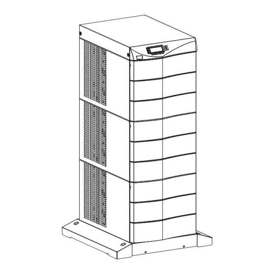
201 Physical Features The Axxium Pro UPS is available in several cabinet sizes. Figure 1, showing the 3-slot and 9-slot configurations, identifies basic Axxium Pro system features. (6-slot and 12-slot cabinets are also available.) External battery cabinets are available in 6-, 9-, and 12-slot sizes. Figure 1. -
Page 8: 202 Functional Features
202 Functional Features The Axxium Pro UPS operates in several different modes. Normally it operates under internal control, called Auto Mode, to automatically protect loads connected to it. It also functions under operator control to enable manual override should servicing or testing be required. Figure 2. -
Page 9: 203 Operator Control Panel
Off mode turns off the output and most internal circuitry. Within this mode, another mode (Sleep) turns off all internal circuitry when AC line is not present and battery voltage drops to a low threshold. If the Battery Protect (BP) function is selected and input AC voltage is not present, the UPS goes into Sleep mode immediately when the UPS is turned off. -
Page 10: 300 Starting The Ups
300 Starting the UPS This section provides step-by-step instructions for starting your Axxium Pro system. Follow these procedures closely to avoid potential damage to your equipment or the UPS and to protect yourself and others from hazardous operating conditions. CAUTION To avoid potential equipment damage or personal injury, assume that the Axxium Pro system power connections (outlets and distribution wiring) may have AC voltage present whenever AC input voltage or DC battery voltage is applied. -
Page 11: Installing Modules
Figure 6. Installing Modules 3.a. Remove the front bezel(s) covering the chassis rack. The bezels have spring latches on the left and right sides that hold them in place. 3.b. Insert battery modules into the chassis rack as shown. Push each module in firmly until the front latch snaps to hold it securely. -
Page 12: 301 Initial Startup Parameters
5. CHECK UPS CONTROL Test proper operation of optional external control signals and computer communication before connecting loads. (See Section 602 for details.) 6. CONNECT EQUIPMENT TO UPS 6.a. Axxium Pro units with receptacles on the back: Plug the equipment into the UPS receptacles. Switch on each piece of equipment. -
Page 13: 400 Using The Front Panel Display
400 Using the Front Panel Display The front panel display, below, shows several important things. The numbers in the upper left corner (for example, 4 24 ) are the display location within the operating menu structure. The word in the top center (for example, USER ) is the security level, which allows various operating parameters to be changed. -
Page 14: 401 Parameters
401 Parameters A parameter is a factor describing how the Axxium Pro system is operating or will operate. Some useful parameters are input and output voltage, input and output current, and battery voltage. The UPS measures or records many other parameters. Some are operator-adjustable, such as the internal date and time and various operating limits. -
Page 15: 404 Menu Map
Weak Battery Battery failure caused by load test. Phase Error Internal error – phone Best Power Worldwide Service or your nearest Best Power office. Module Failure Internal error – phone Best Power Worldwide Service or your nearest Best Power office. -
Page 16: Axxium Pro System Menu Map
Figure 7. Axxium Pro System Menu Map (Menu) 1 Password Enter Password (ESC) (ESC) 2 System Mode Preference Unit Time 3 10 AC Vout Ph. 1 -- N 3 19 Wout 3 20 Wout Ph. 1 -- N Unit Date 3 11 AC Vout Ph. -
Page 17: 500 Alarms
UPS begins recharging batteries and applies power to the load. High Battery The battery voltage is too high because of a Phone Best Power Worldwide Service or your nearest charger problem, battery problem, or incorrect Best Power office. parameter setting. -
Page 18: Typical Active Alarm Display
Phone Best Power Worldwide Service or your nearest Best Power office. Check Battery The batteries have failed an automatic system Phone Best Power Worldwide Service or your nearest Best Power office. test. Low Redundancy The number of active power modules is too low... -
Page 19: 501 Alarm Reason Codes
A power module has detected an Look in the alarm log for the slot number Precharge Failure initialization sequence problem and will of the affected module. Phone Best Power not start up. Worldwide Service or your nearest Best Power office. -
Page 20: 600 Communication
600 Communication 601 Communication Options Best Power offers several methods of communicating with your Axxium Pro system in addition to the operator control panel: CheckUPS ® Each Axxium Pro UPS ships with CheckUPS II power monitoring and unattended-shutdown Software: software and an interface cable. To begin installing CheckUPS software, see the instructions accompanying the CheckUPS software CD-ROM. -
Page 21: 602 Db9 Port Pin Functions
602 DB9 Port Pin Functions The table below explains the functions of the pins on the Axxium Pro DB9 port. This port is on the Axxium Pro UPS back panel, as shown in Figure 5. Table 6. DB9 Port Signals Function RS-232 Receive Data. -
Page 22: 700 Maintenance And Service
700 Maintenance and Service 701 Routine Maintenance Best Power designed your Axxium Pro system to provide years of trouble-free operation. Its internal control system checks the batteries and inverter periodically to ensure reliable operation. In fact, you’ll probably find that your Axxium Pro system requires less maintenance than any of your other computer peripherals. -
Page 23: 703 Power Module Replacement
704 Service and Support The Best Power customer service department stands ready to help you. Please feel free to call, write, e-mail, or fax the nearest Best Power office if you have a problem or question about your Axxium Pro system. Please have your model number and serial number when you call. -
Page 24: Batteries And Battery Charger
2 modules per string) at 7.2 AH. The standard battery charger rating is 1.5 Amp at 120 VDC. Optional battery chargers at higher current ratings (5 – 20 Amp) will be available at a future product release. Call the nearest Best Power office for more information. -
Page 25: Axxium Pro Ups Operating Specifications
Agency Listings and Compliance Safety: All models comply with UL, cUL, TÜV, CE. Emissions: All models comply with (Class A) FCC, ICES, CISPR-22, VCCI, C-tick, BCIQ. Immunity: All models comply with EN 50091-2. Table 7. Axxium Pro UPS Operating Specifications 3 KVA/ 6 KVA/ 9 KVA/... -
Page 26: 900 Warranty
No warranty is made with respect to other products sold by BEST POWER which do not bear the name BEST POWER, and no recommendation of such other product shall imply or constitute any warranty with respect to them. -
Page 27: 902 Limited Warranty
1. The replacement or repair of the transient voltage surge suppression circuitry in each Product that is returned intact to BEST POWER and which shall appear to BEST POWER upon inspection to have been defective in material or workmanship or to have been damaged through normal use;... -
Page 28: 903 Warranty Registration
Please fill out the information listed below for your records. Send a photocopy of this page by mail or by fax to your nearest Best Power office if you can’t register your warranty information online. We recommend that you register your product by using the online registration form. To enter the information online, go to http://www.bestpower.com and select “Warranty Registration”... -
Page 29: 1000 How Do I
These limits should be changed only by authorized personnel. For information about making this or other password-protected adjustments, contact Best Power's Worldwide Service or your nearest Best Power office. - Page 30 Apply power to the loads if the unit won’t operate? Turn the optional external bypass switch to either the Service or the Line position. In these two positions, line power flows directly to the loads. In the Service position, the UPS does not receive line power and may be worked on for maintenance purposes.
-
Page 31: Part Ii Installation Instructions
PART II INSTALLATION INSTRUCTIONS Contents PART I USER INSTRUCTIONS ............3 PART II INSTALLATION INSTRUCTIONS . - Page 32 Figures (continued) 19. Bypass Switch Wiring Label ........46 20.
-
Page 33: 1100 Installation Planning
1100 Installation Planning The information in this section will help you prepare the location of the Axxium Pro system. Section 1303 describes the various configurations for input and output power connections. 1101 Dimensions The table below contains overall cabinet dimensions and empty cabinet weights. -
Page 34: 1103 Rack Mounting Guidelines
1103 Rack Mounting Guidelines Figure 10a. Metal Clip-nut and The 3-slot and 6-slot UPS cabinets may be installed in an EIA-standard Tab Slot Locations 19-in. (483-mm) equipment rack. An optional rack mounting kit, containing brackets and required hardware, is available for such an installation. -
Page 35: 1104 Floor Anchor Kit Requirements
1104 Floor Anchor Kit Requirements An optional floor anchor kit is available for all sizes of Figure 11. Floor Anchor Brackets the Axxium Pro UPS. The kit helps to stabilize the UPS Bolted to UPS Cabinet or battery cabinet in the event of accidental bumps or small floor movements. -
Page 36: 1106 Stabilizer Bracket Requirements
1106 Stabilizer Bracket Requirements The 12-slot Axxium Pro UPS cabinet with non-isolated outputs is shipped with two stabilizer brackets. These brackets must be attached to the wall or the floor behind the UPS cabinet. Under all module-loading conditions, they act as a protective stop to prevent the cabinet from falling forward if it is unintentionally pushed away from the wall. -
Page 37: 1107 Location Requirements
If additional Axxium Pro system batteries are in a separate cabinet, the battery cabinet should be located as close as possible to the Axxium Pro UPS. If the batteries will be further from the unit than the standard cables allow, contact your nearest Best Power office for assistance. 1108 Moving the Axxium Pro UPS and Battery Cabinets Refer to Section 1200 for information about initial equipment unpacking. -
Page 38: 1109 Storage And Operation Environments
1110 Bypass Switches If your Axxium Pro UPS does not have a power cord and plug, it is recommended that you install a Best Power bypass switch to enable power transfer during maintenance or UPS downtime. Mount the bypass switch on the wall, within sight of the UPS or the load distribution panel. - Page 39 “UPS” to “LINE,” the switch disconnects your protected equipment from UPS output power before connecting the equipment to AC input power. Best Power bypass switches that may be used for the Axxium Pro UPS are available in six models, as specified in Table 10.
-
Page 40: 1200 Ups Unpacking And Setup
1200 UPS Unpacking and Setup The Axxium Pro UPS is shipped in a carton on a shipping pallet. Power and battey modules are shipped in separate boxes on another pallet. NOTE: As they are unpacked, check to make sure all Axxium Pro UPS power modules are the proper type for the UPS cabinet: Single-phase (universal) modules have white labels;... -
Page 41: 1300 Ups And Bypass Switch Installation (For Qualified Personnel Only)
With all casters fully extended, carefully roll the cabinet down the ramp and to its intended operating location. To stabilize the cabinet in its operating location, turn the four caster bolts counter-clockwise until the cabinet rests on the floor. Place a plastic cap into each bolt access hole. NOTE: If the floor is uneven and the cabinet is tilted or unstable, you may need to place a thin steel plate under a corner to make the cabinet stand vertical. -
Page 42: 1302 Installing External Bypass Switches
1302 Installing External Bypass Switches For hardwired UPS installations, the bypass switch must be incorporated in the fixed wiring and be readily accessible. Table 12 contains information for selecting the proper size conductor to carry power from the service distribution panel to the external bypass switch, and from the external bypass switch to the load distribution panel. -
Page 43: 1303 Installation Overview
1303 Installation Overview The Axxium Pro UPS may be installed with the input (mains) connection hard wired through conduit to either a supply (mains) circuit breaker or an optional external bypass switch. If a bypass switch is used, both UPS input and UPS output must be hard wired–through separate conduits–to the bypass switch, as shown in Figure 14. -
Page 44: 1304 Determining Input/Output Voltage And Selecting Power Module Type
1304 Determining Input/Output Voltage and Selecting Power Module Type Sections 1305 through 1308 contain the various input and output connections for all possible Axxium Pro UPS configurations. Table 13 relates input and output configurations to the wiring diagrams specific to your particular system requirements. -
Page 45: 1305 Ups Input Wiring Connections
Figure 17. The other end of the wire (*) must be attached to the proper output neutral terminal, as specified in Figure 22. If there is any question as to the need for this bond wire, contact your local regulatory agency or Best Power Worldwide Service. -
Page 46: 1307 Ups Installation With An External Bypass Switch
1307 UPS Installation with an External Bypass Switch 1. Mount the bypass switch within sight of the UPS. If you do not have a Best Power bypass switch or the fuse box or panel is out of sight, you must install a separate disconnect switch next to the UPS. - Page 47 7. If your UPS has an isolated output, find the proper output neutral-to-ground connection in Figure 22. At the UPS terminals, connect the neutral-to-ground (neutral-to-earth) wire to the proper terminal before making any other connections to the UPS. The neutral-to-ground wire is a green and yellow wire. One end of this wire is already connected to the ground (earth) UPS terminal.
-
Page 48: 1308 Ups Output Wiring Connections
1308 UPS Output Wiring Connections Figures on this and the next page describe output wiring configurations for various output voltages. Find the desired output voltage and single- or split-phase configuration below, and connect the output AC wiring to the proper Axxium Pro system power terminals. You must also set the operating menu parameter 7-3-4 for the required output voltage as shown in the wiring configuration drawings. - Page 49 Figure 22e. Universal Modules With 2-wire Plus Ground Isolated Output 50 or 60 Hz 208, 220, 230 or 240 V Out * with Isolated Output Option Parameter 7-3-4 set to 208, 220, 230, or 240, as required.
- Page 50 Figure 23: Installation Wiring Diagram for Axxium Pro Systems with External Bypass Switch (L1, N), Isolated Output, and Universal Power Modules • 220 Input, 220 Output • 240 Input, 240 Output • 230 Input, 230 Output Note 1 Note 4 Note 2 Note 4 AC TO...
- Page 51 Figure 25: Installation Wiring Diagram for Axxium Pro Systems with External Bypass Switch (L1, L2, N), Isolated Output, and Universal Power Modules • 220 Input, 220 Output • 240 Input, 240 Output • 230 Input, 230 Output Note 1 Note 4 Note 2 Note 4 L1 L2...
- Page 52 Figure 26: Installation Wiring Diagram for Axxium Pro Systems with External Bypass Switch (L1, N), Non-isolated Output, and Universal Power Modules • 220 Input, 220 Output • 240 Input, 240 Output • 230 Input, 230 Output Note 1 Note 4 Note 2 Note 4 AC TO...
- Page 53 Figure 28: Installation Wiring Diagram for Axxium Pro Systems with External Bypass Switch (L1, L2, N), Non-isolated Output, and Split-phase Power Modules • 110/220 Input, 110/220 Output • 100/200 Input, 100/200 Output • 120/208 Input, 120/208 Output • 127/220 Input, 127/220 Output •...
- Page 54 Figure 29: Installation Wiring Diagram for Axxium Pro Systems with No External Bypass (L1, N), Isolated Output, and Universal Power Modules • 220 Input, 220 Output • 240 Input, 240 Output • 230 Input, 230 Output Note 1 Note 4 Note 4 Note 7 Note 9...
- Page 55 Figure 31: Installation Wiring Diagram for Axxium Pro Systems with No External Bypass (L1, L2, N), Isolated Output, and Universal Power Modules • 220 Input, 220 Output • 240 Input, 240 Output • 230 Input, 230 Output Note 1 Note 4 N L1 Note 4 Note 7...
- Page 56 Figure 32: Installation Wiring Diagram for Axxium Pro Systems with No External Bypass (L1, N), Non-isolated Output, and Universal Power Modules • 220 Input, 220 Output • 240 Input, 240 Output • 230 Input, 230 Output Note 1 Note 4 Note 4 Note 7 Note 9...
- Page 57 Figure 34: Installation Wiring Diagram for Axxium Pro Systems with No External Bypass (L1, L2, N), Non-isolated Output, and Split-phase Power Modules • 110/220 Input, 110/220 Output • 100/200 Input, 100/200 Output • 120/208 Input, 120/208 Output • 127/220 Input, 127/220 Output •...
-
Page 58: 1309 Balancing Receptacle Loads
1309 Balancing Receptacle Loads For Axxium Pro UPS outputs that do not have hard-wired outputs, it is recommended to divide loads between upper and lower receptacles as equally as possible. Whether the cabinet has one panel containing eight receptacles, two panels containing 16 receptacles, or three panels containing 24 receptacles, you should try to supply half of the UPS output through the upper half of the receptacles (X1) and the other half through the lower half of the receptacles (X2), as shown in Figure 35. -
Page 59: 1400 Connecting The External Battery Cabinets
1400 Connecting External Battery Cabinets CAUTION! Before making connections between the UPS and an external battery cabinet or between series-connected (daisy-chained) battery cabinets, remove all input AC power to the UPS. Do this by opening the input service circuit breaker or by turning the external bypass switch to the Service position. Also, disconnect all battery strings in the UPS and in the external battery cabinet, to ensure DC voltage is removed from the internal DC buses. - Page 60 tabs between the stud block and the fuse end and Figure 38. Battery Cable Assembly Installation between the other stud block and the cable terminal. 11. Align the screw holes of the cable assembly’s entry plate with holes on the cabinet side panel as shown in Figure 38.
Need help?
Do you have a question about the 0650 SERIES and is the answer not in the manual?
Questions and answers