Table of Contents
Advertisement
Advertisement
Table of Contents

Related Manuals for Danaher Motion S200-VTS


Summary of Contents for Danaher Motion S200-VTS
- Page 1 S200-VTS Product Manual Base & SynqNet Hardware Installation Manual Control Logic Version 3.0 or Higher Revision C1 May 08,2008 ® Keep all product manuals as a product component during the life span of the servo amplifier. Pass all product manuals...
- Page 2 05/2008 Transfer A4 size, cover page design, EU version © 2006, 2007, 2008 Danaher Motion - All rights reserved. Technical changes to improve the performance of the equipment may be made without prior notice! Printed in the Federal Republic of Germany All rights reserved.
-
Page 3: Table Of Contents
Emulated Encoder Output Signals ..........18 3.9.4 General SFD Specifications ............18 Quick Start Guides.................19 S200 Base Unit Drive ................19 4.1.1 S200 Tools Software Installation..........19 4.1.2 Hardware Setup ................20 4.1.3 S200 Tools Communications Wizard ........20 4.1.4 Motor Feedback Configuration ..........22 4.1.5 Save Options................22 S200-VTS Product Manual... - Page 4 SynqNet Option Card Wiring .............. 59 6.10 J11 – SynqNet IN Port Connector ............60 6.10.1 SynqNet LEDs................60 6.11 J12 – SynqNet OUT Port Connector ..........61 6.11.1 SynqNet LEDs................61 6.12 J13 – Discrete I/O Connector ............. 62 S200-VTS Product Manual...
- Page 5 Accessing Individual Parameters ..........101 9.3.4 Accessing an Entire Parameter Set ........101 Accessories, Connector Kits, and Cables .........105 10.1 Accessories ..................105 10.2 Connector Kits ...................105 10.3 Cables ....................105 Diagnostics and Troubleshooting ............106 11.1 Drive Fault Codes................106 11.2 Diagnostics..................108 11.2.1 Fault Generation..............111 S200-VTS Product Manual...
- Page 6 Appendix B – Cables ..................119 Long Cables ..................119 Custom Composite Cables............... 119 Appendix C – Danaher Motion Linear Motor Wiring ........121 Appendix D – Process to Setup Non-Danaher Motors ........ 122 Detailed Drive Motor Wiring Discovery Procedure ......123 Appendix E –...
-
Page 7: S200 Series Drives
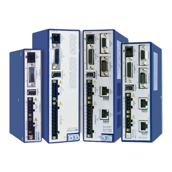
S200 SERIES DRIVES Industry-Leading Performance In A Small Package Danaher Motion’s S200 brushless servo drives puts high performance servo technology into a full power range family with dc input and ac input family members. Particularly for lower power applications the S200 family provides a higher performing more robust option than was previously possible without having to compromise on reliability or package size. -
Page 8: Model Number
S200 90 VDC, 3/9 ARMS Base Unit S20630-VTS S200 90 VDC, 6/18 ARMS Base Unit S2xx30-SRS One of the above drives with optional SynqNet with RJ-45 connectors S2xx30-SDS One of the above drives with optional SynqNet with Micro-D connectors S200-VTS Product Manual... -
Page 9: Before You Begin
Upon receipt of the equipment, inspect components to ensure that no damage has occurred in shipment. If damage is detected, notify the carrier immediately. Check all shipping NOTE material for connector kits, documentation, diskettes, CD- ROM, or other small pieces of equipment. S200-VTS Product Manual... -
Page 10: Specifications
Continuous Power (W) 1000 1500 2500 @36Ω @25Ω @15Ω @15Ω @10Ω Maximum Regen Duty Cycle (%) @36Ω @25Ω @15Ω @15Ω @10Ω Regen Resistance (Ω) 25 – 50 25 – 50 12 – 50 8 – 50 8 – 50 S200-VTS Product Manual... - Page 11 Total drive dissipation = power stage dissipation + control power. Control power adder is: Base unit only = 7W Base plus option card = 10W For 120 Vac voltage doubled operation of S20250, S20350 units see Appendix D for power specifications. S200-VTS Product Manual...
-
Page 12: Ac Input Drives - Control And Power
FRN-R -8 FRN-R -15 JKS-20 JKS-30 240 VAC 1 Phase Bussmann Bussmann Bussmann Bussmann Bussmann (ARMS) FRN-R -5 FRN-R -10 FRN-R -20 JKS-30 JKS-30 120 VAC 1 Phase Bussmann Bussmann Bussmann (ARMS) FRN-R -5 FRN-R -10 FRN-R -20 S200-VTS Product Manual... -
Page 13: Ac Control Power Inrush Current & Fusing
Pure sinusoidal or six-step, *Drive I depending on feedback device Motor Shaft Torque (Ignoring motor magnetic saturation) Peak (hot motor winding) (N-m/ARMS)*Drive Ipeak (ARMS) Multiply K by 1.06 for cold motor winding (AKM or PMA motors). Instantaneous (N-m/ARMS)*IFB (ARMS) S200-VTS Product Manual... -
Page 14: Current Loop Bandwidth
0.00044 to 0.106 (Ipeak) KVP Range (Depends on Ipeak) (1/rad/sec) KVP Resolution (%) 0 or 0, 0.0238 to 753.9 KVI Range (Hz) KVI Resolution (%) 1.518 to 96382 ARF0 Range (Hz) 1.518 to 96382 ARF1 Range (Hz) S200-VTS Product Manual... -
Page 15: Command I/O
Pulse Width Distortion (ns) 3.6.4 MSINP - Direction Command MSINP - J4-5, J4-1 ± (4.0 - 30.0) Input Voltage (volts) 0.65 - 6.7 Input Current (mA) Direction Setup Time ( µs ) Minimum Pulse Width ( µs ) S200-VTS Product Manual... -
Page 16: Quadrature Input
Response Time (ms) 3.6.8 Quadrature Outputs Quadrature Output CHA- J4-19, 20 CH B- J4-21,22 CHZ- J4-17,18 RS-422/RS-485 Type 5.0 V Differential Output - Output Voltage (volts) Unloaded 1/2 Quadrature Count corresponding to 1/8 Hysteresis Encoder Line Count S200-VTS Product Manual... -
Page 17: Mechanical
Rev/°C = 0.08 arc min/°C DC Offset Temperature Drift Absolute Accuracy -10.3 AKM1 (arc min) ± 2 Rev = ±17 -11.1 AKM2 or 3, 4, 5, 6, 7 (arc min) ± 2 Rev = ±10 51.2 Communications Update Period (µs) S200-VTS Product Manual... -
Page 18: Velocity Signal
> 2000 -3 dB Bandwidth (Hz) > 1000 -45° Phase Lag (Hz) > 48600 Max Tracking Rate (rpm) 25000 Max Recommended Rate (rpm) > 16x10 Max Tracking Acceleration (rpm/sec) 50 m (164 ft) Maximum Feedback Cable Length S200-VTS Product Manual... -
Page 19: Quick Start Guides
Follow the installation instructions from the CD-ROM or zip file. S200 Tools supports the following Operating Systems: • Windows 2003 Server • Windows XP, All Service Packs – (SP) • Windows 2000, SP2 • Windows XP embedded • Windows NT4, SP6 S200-VTS Product Manual... -
Page 20: Hardware Setup
Launch S200 Tools Launch the S200 Tools program by clicking the desktop icon or from the Windows Start button (Programs > Danaher Motion > S200Tools). The default location for S200Tools.exe, is (C:\Program Files\Danaher Motion\S200Tools). When the S200 Tools program is launched for the first time, no drives should be listed under the Online or Offline Communications Mode. - Page 21 If you receive the "No Connection" message, check the hardware connections. After you have confirmed your setup, click the OK button. The installed S200 drive(s) will now be listed as "Online" and will list its configuration and status options. S200-VTS Product Manual...
-
Page 22: Motor Feedback Configuration
Follow the installation instructions from the CD-ROM or zip file. See S200 Tools Software Installation Guide. S200 Tools supports the following Operating Systems: • Windows 2003 Server • Windows XP, All Service Packs - (SP) • Windows 2000, SP2 • Windows XP embedded • Windows NT4, SP6 S200-VTS Product Manual... -
Page 23: Hardware Setup
NOTE: Although you can connect other SynqNet supported nodes/drives on the SynqNet network, you will only be able to configure the S200 Series Drives with the S200 Tools software. S200 Tools will only communicate with S200 Series Drives. S200-VTS Product Manual... -
Page 24: S200 Tools Communication Wizard
Launch S200 Tools Launch the S200 Tools program by clicking the desktop icon or from the Windows Start button (Programs > Danaher Motion > S200Tools). The default location for S200Tools.exe, is (C:\Program Files\Danaher Motion\S200Tools). When the S200 Tools program is launched for the first time, no drives should be listed under the Online or Offline Communications Mode. - Page 25 If there are additional S200 nodes on the network, they are automatically discovered. When using a network with multiple SynqNet nodes, use the SynqNet controller/node pulldown bars to select a particular node on the network to display in the Online mode. S200-VTS Product Manual...
-
Page 26: Synqnet Configuration
Select Option Card Feedback if the motor feedback is connected to J14 on the S200 Drive. 4.2.6 Motor Feedback Configuration The next step is to set the proper motor feedback configurations. 4.2.6.1 If you are using SFD motor feedback, no further configuration is needed. S200-VTS Product Manual... -
Page 27: Save Options
Offline mode and clicking the Download NV/Drive buttons once the proper drive is selected in the Online mode. It is recommended that you save a configuration file for each setup. S200-VTS Product Manual... -
Page 28: Mounting The Drive
1.69 lb 1.86 lb 2.93 lb 0.88 lb 1.10 lb 5.64 lb Depth measurement is for drive only. Add approximately 50.8 mm (2 in) to depth given in the table to accommodate mating connectors and wire bend radius. S200-VTS Product Manual... - Page 29 M4 or #8 Hardware Drive Height Vertical Mounting Height For Drive Mounting Side Clearance use M4 or #8 Hardware Drive to Drive Mounting Bottom Clearance Side Clearance Mounting Dimensions - Front View See the preceding table for mounting dimensions. S200-VTS Product Manual...
-
Page 30: Mechanical Outline Drawings
Note: All S20660-VTS dimensions are exactly as shown above except for the product width. The 2.16 in [54.75 mm] width above changes to 2.52 in [64.0 mm] for the S20660-VTS. Enclosure and mounting dimensions for Option card equipped units are the same. S200-VTS Product Manual... -
Page 31: Base Ac Drive (S21260-Vts)
TOP VIEW 31.7 [1.25] 76.1 [3.00] 4.8 [0.19] 169.5 [6.67] 178.8 [7.04] 4.6 [0.18] FRONT VIEW RIGHT SIDE VIEW REAR VIEW Dimensions are mm [inches] Note: Enclosure and mounting dimensions for Option card equipped units are the same. S200-VTS Product Manual... -
Page 32: Base Ac Drive (S22460-Vts)
Mounting the Drive 05/2008 Danaher Motion 5.2.3 Base AC Drive (S22460-VTS) Note: Enclosure and mounting dimensions for Option card equipped units are the same. S200-VTS Product Manual... -
Page 33: Base Dc Drive (S20330-, S20630-Vts)
Danaher Motion 05/2008 Mounting the Drive 5.2.4 Base DC Drive (S20330-, S20630-VTS) Note: Enclosure and mounting dimensions for Option card equipped units are NOT the same. See Section 5.2.6 for details. S200-VTS Product Manual... -
Page 34: Synqnet Ac Drive (S20260-, S20360-, S20660-Srs)
DIMENSIONS ARE IN INCHES [MM] Note: All S20660-SRS, S20660-SDS dimensions are exactly as shown above except for the product width. The 2.16 in [54.75 mm] width above changes to 2.52 in [64.0 mm] for the S20660-SRS, S20660-SDS. S200-VTS Product Manual... -
Page 35: Synqnet Dc Drive (S20330-, S20630-Srs)
0.18 4.57 Ø 0.18 RECOMMENDED MOUNTING 4.57 HARDWARE: #8 or M4 TOPVIEW 0.97 24.64 1.90 48.26 0.16 4.06 6.00 5.68 152.40 ] 144.27 ] 0.16 REARVIEW RIGHT SIDEVIEW FRONT VIEW 4.06 ] DIMENSIONS ARE IN INCHES [MM] S200-VTS Product Manual... -
Page 36: Wiring The Drive
READ these instructions before connecting power. Damage can result from MISWIRING at the power terminals. DANGEROUS voltages are present on power input and motor output WARNING terminals. AC Input Drive Wiring 6.1.1 AC Drive (S20260-, S20360-, S20660-VTS) S200-VTS Product Manual... -
Page 37: Ac Drive (S21260-, S22460-Vts)
Danaher Motion 05/2008 Wiring the Drive 6.1.2 AC Drive (S21260-, S22460-VTS) S200-VTS Product Manual... -
Page 38: J1 - Ac Input Drive Power
12 – 24 AWG Wire Range, Phoenix FKC 2,5/9-SFT-5,08-BK Crimp Connector Crimp Shell 14-20 AWG Wire Range, Phoenix MSTBC 2,5/9-STZF-5,08-BK Crimp Contact 14-16 AWG Wire Range, Phoenix MSTBC-MT 1,5-2,5 Crimp Contact 18-20 AWG Wire Range, Phoenix MSTBC-MT 0,5-1,0 Refer to http://www.phoenixcon.com. S200-VTS Product Manual... - Page 39 85 VAC to 265 VAC single phase Input Voltage Range (RMS) 47 to 63 Hz 120 VDC to 375 VDC 10 A 0-p with 240 VAC Input Inrush Peak Current 1.60 ms Inrush pulse width Bussmann MDA – ½ Fusing S200-VTS Product Manual...
- Page 40 Bussmann Bussmann Bussmann (ARMS) FRN-R-5 FRN-R-8 FRN-R-15 JKS-20 JKS-30 240 VAC 1 Phase Bussmann Bussmann Bussmann Bussmann Bussmann (ARMS) FRN-R -5 FRN-R-10 FRN-R-20 JKS-30 JKS-30 120 VAC 1 Phase Bussmann Bussmann Bussmann (ARMS) FRN-R -5 FRN-R-10 FRN-R-20 S200-VTS Product Manual...
-
Page 41: Dc Input Drive Wiring
Danaher Motion 05/2008 Wiring the Drive DC Input Drive Wiring S200-VTS Product Manual... -
Page 42: J1 - Dc Input Drive Power
Protective Earth connection point. This chassis ground point must be Screw connected to Protective Earth ground. The connection at the Protective Connection Earth ground end must be hard wired (do not use a pluggable connection). A ground fault detector (RCD) cannot be depended on for safety. S200-VTS Product Manual... -
Page 43: Dc Power Supply Requirements
Target design center voltage for unregulated supply is +70 to +75 VDC. This provides 15 to 20 VDC margin for line tolerance, transformer regulation, and regen pump up. Design center voltage for a regulated supply can be up to +80 VDC. S200-VTS Product Manual... -
Page 44: Control Voltage
(1,000 µf, 100 V) across the drive bus terminals (J1-3 to J1-2). If the buses of individual drives are to be fused, select the fuse type and rating for high margin. S20330 (3 amp) S20630 (6 amp) 7 A, Slo-Blo (Bussmann MDA-7) 15 A, Slo-Blo (Bussmann MDA-15) S200-VTS Product Manual... -
Page 45: J2 - Motor Power Connector
Observe motor polarity, connect phase U on the drive to phase U on the motor, etc. For nonstandard motor drive combinations see Appendix D – Process To Set Up Non-Danaher Motors or consult the factory for NOTE proper phase orientation. S200-VTS Product Manual... -
Page 46: J3 - Feedback Connector
J3-6 device. CW (Commutation Phase W) input when NC / CW using open collector Hall feedback. This input has a 2.21 kW pull-up resistor to 3.3 V. Outer shield connection (wired to PE in the drive). Shell S200-VTS Product Manual... -
Page 47: J4 - Command I/O Connector
± 4.0 to MSINP1 ± 30 V. General purpose inputs are J4-5 compatible with either sourcing or sinking currents to provide maximum flexibility for Common Input interfacing to field wiring. Terminal J4-1 S200-VTS Product Manual... - Page 48 DINP4 has a response time of less than 100 µs. For fastest response to an input, configure the drive to respond when the input optoisolator is turned on (current starts flowing in the photo diode). NOTE Response time is cut approximately in half. S200-VTS Product Manual...
- Page 49 For compatibility with sinking outputs, the DINP COM terminal is Sinking Logic connected to the positive terminal of a power source (4.0 to 30 VDC). The input (DINP1-4) is connected to the sinking logic output of the field device as shown in the diagram below. S200-VTS Product Manual...
- Page 50 J4-2, 3, 4, 5 DINP1-4 The following are examples of driving with TTL or CMOS TTL and CMOS output devices. Drivers +5 VDC 4.32 k 4.64 k SINKING TTL or CMOS +5 VDC 4.32 k 4.64 k SOURCING CMOS S200-VTS Product Manual...
-
Page 51: General Purpose Outputs
1.0 V at 10 mA 1.2 V at 50 mA 5 µA 1 ms Response Time 33 V (nominal) Clamp Voltage The outputs are not short circuit protected. Configure the application to ensure the maximum current is not exceeded. CAUTION S200-VTS Product Manual... - Page 52 The voltage of the external power source needs to be 30 VDC or less and can be the same source used to provide power to the inputs. A clamp diode must be added across the coil to clamp the voltage during turn-off. S200-VTS Product Manual...
-
Page 53: High Speed Input
The differential driver needs to deliver a minimum of 3.0 V to the input terminals on J4. A CMOS driver is recommended. J4-10 Twisted Pair HSINP1+ Wiring 3.0 V Min. 5 V Differential J4-11 Driver - CMOS HSINP1- S200-VTS Product Manual... -
Page 54: Sfd Bat
Connect one of the I/O RTN pins to an earth ground point in the cabinet reserved for single point grounding of all returns (drives and supplies) to control common mode voltage. S200-VTS Product Manual... -
Page 55: Encoder Outputs/Inputs
A generates a CCW position command. The magnitude of the command position is set by GearIn and GearOut. The maximum input line frequency for reliable operation is 625 kHz, which corresponds to a maximum quadrature pulse rate of 2.5 MHz. S200-VTS Product Manual... -
Page 56: Analog Command Input
NOTE signal ground. The direction of rotation of the motor can be changed by swapping the ANA CMD input connections or changing the sign of the CmdGain NV Parameter. S200-VTS Product Manual... -
Page 57: J5 - Serial Port Connector
'Serial' instead of 'SynqNet' as the Communications Mode in the S200Tools Communication Wizard, the drive will appear configured in the interface, but the SynqNet Options tab will not appear under the Drive Setup options. S200-VTS Product Manual... -
Page 58: Serial Interface Specification
Cable wiring diagrams for connecting to either 9 or 25-pin serial ports of most computers are also shown. Pinouts vary among computer manufacturers. Check the hardware reference manual for your machine before wiring. NOTE To J5 To PC on Drive 9 Pin Female To J5 To PC on Drive 25 Pin Female S200-VTS Product Manual... -
Page 59: Synqnet Option Card Wiring
OINP3 (NEGLIMIT IN) OINP4 (NODE DISABLE) CONN_TD0+ GP RS422 IN3+ CONN_TD0- GP RS422 IN3- CONN_RD0+ OOUT1+ CONN_TTERM0 OOUT1- CONN_TTERM0 I/O RTN CONN_RD0- I/O RTN CONN_RTERM0 GP RS422 IN0+ CONN_RTERM0 GP RS422 IN0- GP RS422 IN1+ GP RS422 IN1- S200-VTS Product Manual... -
Page 60: J11 - Synqnet In Port Connector
SynqNet LEDs Meaning Description ON = Tx and Rx active (cyclic phase) Network Status Activity BLINK = Tx only active (discovery phase) STAT OFF = Idle (shutdown phase) ON = Link Active Link Activity OFF = Link Inactive S200-VTS Product Manual... -
Page 61: J12 - Synqnet Out Port Connector
SynqNet LEDs Meaning Description ON = Repeater on, network cyclic RPTR Repeater BLINK = Repeater on, network not cyclic OFF = Repeater off, power off, or reset ON = Link Active Link Activity OFF = Link Inactive S200-VTS Product Manual... -
Page 62: J13 - Discrete I/O Connector
I/O refer to Sections 6.7.1 General Purpose Inputs and 6.7.2 General Purpose Outputs. J13 also includes 3 channels of very fast RS-422 compatible direct coupled differential digital inputs that can be used for very high speed registration or probing functions. S200-VTS Product Manual... -
Page 63: J13 - Discrete I/O Connection Schematic
Danaher Motion 05/2008 Wiring the Drive 6.12.1 J13 – Discrete I/O Connection Schematic S200-VTS Product Manual... -
Page 64: J14 - Aux Fb Connector
AKM Motor Feedback Option DB or other EnDat 2.1 EnDat 2.2 Encoders operating in 2.1 compatibility mode both rotary and linear including absolute types Run - Commutate the motor and close the servo loops. FB - Use as a secondary feedback to SynqNet master. S200-VTS Product Manual... -
Page 65: Auxiliary Feedback Sin-Cos Interpolation Scaling
AuxFBDivisor best suits the application. However, if the NV parameter FBSrc is set to Option Card, then AuxFBDivisor must be set to the specific value which will properly electronically commutate the motor work. S200-VTS Product Manual... -
Page 66: Basic Configuration
Drive parameter settings can override the S2 switch settings. To enable S2 for setup verify that the following drive parameters are set as shown below. The factory default is to ship the drive with the switches enabled: Parameter Value NOTE SetupS2-1 OpMode SetupS2-2 CommMode S200-VTS Product Manual... -
Page 67: S1 - Rotary Setup Switch
The value written replaces the factory default value listed in position 0 of the table. The emulated encoder output is only available when using SFD feedback to the base unit or a high-resolution feedback NOTE device connected to the option card. S200-VTS Product Manual... -
Page 68: S11, S12 - Rotary Synqnet Id Switches
To set a SynqNet ID to an S200 drive, turn the S11 LSB (Least Significant Bit) and S12 MSB (Most Significant Bit) switches to a desired letter/number combination. The SynqNet ID can then be read using the following utilities: Motion Console and Version.exe Utility. S200-VTS Product Manual... - Page 69 In the SqNode Summary window, under the Info tab, the SynqNet ID is displayed in the Switch ID field. See screenshot below. SYNQNET ID S11 = 5 S12 = A 7.1.3.2 Version.exe Utility The version.exe utility also displays the Switch ID field. See screenshot below. SYNQNET ID S11 = 5 S12 = A S200-VTS Product Manual...
-
Page 70: Configuring For Brush Motors
Selects Analog, PWM, or Command variable for command. CmdSrc Sets the command gain for the command input. CmdGain Sets the command offset for the command input. CmdOffset Sets the filtering on analog input commands. CMDF0 EnInhibitCW Enables the hardware over travel limits. EnInhibitCCW S200-VTS Product Manual... -
Page 71: Configuring With 6-Step (Hall) Feedback
Sets the source of the command, analog or command variable. CmdSrc Sets the command gain for the command input. CmdGain Sets the command offset for the command input. CmdOffset Sets the filtering on analog input commands. CmdF0 S200-VTS Product Manual... -
Page 72: 6-Step Velocity Mode
Sets the line count of the emulated encoder output. With 6-Step feedback the EncOut emulated encoder output works by interpolating between the edges. So, at low speeds signal quality will be poor. EnInhibitCW Enables the hardware over travel limits. EnInhibitCCW S200-VTS Product Manual... -
Page 73: Configuring With Sfd Feedback
Velocity loop proportional gain. Current loop proportional gain. Drive pole pairs. DPoles Speed of response for motor transient thermal protection. I2TF0 Fault trip level for motor transient thermal protection. I2TTrip Clamps drive maximum Iout based on motor Ipeak. IlmtPlus, IlmtMinus S200-VTS Product Manual... -
Page 74: Sfd Torque/Current Mode
Sets the filtering on analog input commands. CMDF0 The following are optional parameters that can be set. Parameter Function Sets the line count of the emulated encoder output. EncOut EnInhibitCW Enables the hardware over travel limits. EnInhibitCCW S200-VTS Product Manual... -
Page 75: Sfd Velocity Mode
Sets the filtering on analog input command. CmdF0 The following are optional parameters that can be set. Parameter Function Sets the line count of the emulated encoder output. EncOut EnInhibitCW Enables the hardware over travel limits. EnInhibitCCW S200-VTS Product Manual... -
Page 76: Sfd Position Mode
The following are optional parameters that can be set. Parameter Function EncOut Sets the line count of the emulated encoder output. NOTE : Emulated Encoder Outputs are not available when the PosSrcCmd is set to AQuadB. EnInhibitCW Enables the hardware over travel limits EnInhibitCCW S200-VTS Product Manual... -
Page 77: Reversing Motion Direction
To reverse the Emulated Encoder Outputs from the drive: • Reverse the Emulated Encoder Outputs if the external control loops use the emulated encoder outputs for feedback. • Swap the CHA and CHA/ emulated encoder outputs (J4-19 and J4-20) going to the external controller. S200-VTS Product Manual... -
Page 78: Advanced Configuration
S200Tools. The rest of this chapter describes the S200 configuration options through diagrams of the control loops, reference lists of setup parameters with their definitions and range, and further explanations of drive capabilities. S200-VTS Product Manual... -
Page 79: Base Drive Torque/Velocity Control Block Diagram
Danaher Motion 05/2008 Advanced Configuration Base Drive Torque/Velocity Control Block Diagram S200-VTS Product Manual... -
Page 80: Base Drive Position Control Block Diagram
Advanced Configuration 05/2008 Danaher Motion Base Drive Position Control Block Diagram S200-VTS Product Manual... -
Page 81: Synqnet Drive Torque Control Block Diagram
Danaher Motion 05/2008 Advanced Configuration SynqNet Drive Torque Control Block Diagram S200-VTS Product Manual... -
Page 82: Synqnet Drive Velocity Control Block Diagram
Advanced Configuration 05/2008 Danaher Motion SynqNet Drive Velocity Control Block Diagram S200-VTS Product Manual... -
Page 83: Parameters And Variables
DIpeak ARMS VBusScale Relative x Description S20260 240 VAC 4.5 ARMS peak S20360 240 VAC 9 ARMS peak S20660 240 VAC 18 ARMS peak S20330 0.25 90 VDC 9 ARMS peak S20630 0.25 90 VDC 18 ARMS peak S200-VTS Product Manual... -
Page 84: Read/Write Nv Parameters
AuxFBDivisor Incremental A Quad B Enable Disable AuxFBDivisor with Halls 1 Vp-p Sin-Cos Disable Disable AuxFBDivisor Incremental 1 Vp-p Sin-Cos Inc. with Enable Disable AuxFBDivisor Halls EnDat 2.1 Disable Enable AuxPPR EnDat 2.1 Linear Disable Enable AuxFBDivisor S200-VTS Product Manual... - Page 85 See CmdSrc for this setting and CmdGain for scaling the gain of the input command. Expressed as an equation: CmdIn = [(User Input) – CmdOffset] * CmdGain S200-VTS Product Manual...
- Page 86 This parameter selects the polarity of the Dinp3. When this parameter is set, the input to the FPGA is inverted before it is used by the logic. This parameter affects the sense of the InhibitCCW I/O input. The following describes the different values for this parameter. 0 - Normal 1 - Invert S200-VTS Product Manual...
- Page 87 240 VAC 4.5 ARMS peak S20260 240 VAC 4.5 ARMS peak S20330 0.25 90 VDC 9 ARMS peak S20350 240 VAC 9 ARMS peak S20360 240 VAC 9 ARMS peak S20630 0.25 90 VDC 18 ARMS peak S200-VTS Product Manual...
- Page 88 Z CH output at the right point in a machine cycle to be used to trigger an action like a camera. EncOutZOffset can be used to position the Z CH OUT pulse a the exact desired position. S200-VTS Product Manual...
- Page 89 LED fault blink code. The DOUT1 line output is still static high for drive off. See FaultCode entry for a chart giving the blink counts for each fault. 0 - OFF (default) 1 - Diagnostic Blink Code S200-VTS Product Manual...
- Page 90 When the motor includes a thermal sensor I2TTrip is typically set 1.25 times larger than the motor’s continuous current capability with the motor’s internal thermal sensor providing protection against small overloads. S200-VTS Product Manual...
- Page 91 Note: With SynqNet OpMode is written to by the SynqNet master over the network each network update period. All SynqNet master versions that support the S200 can work in Torque/Current mode. Newer SynqNet master versions can optionally be set to run the drive in Velocity Mode. S200-VTS Product Manual...
- Page 92 SFD communication error. Recommended (default) setting is Span. 0 - No Span 1 - Span SWClrFault Not Clear or Clear This parameter will clear the fault logic. 0 - Not Clear (default) 1 - Clear S200-VTS Product Manual...
-
Page 93: Status And Control Variables
OpMode = Position, PosCmdSrc = Step-Dir this input is the Direction input. In the inactive state, no LED current, with positive GearOut PosCmd increments with each Step input edge, i.e. the motor moves clockwise. 0 - Active state, current flows in opto isolator input diode. 1 - Inactive state, no current flow. S200-VTS Product Manual... - Page 94 SFD UART framing error Drive output over current SFD frame timeout Option card read timeout SFD transfer incomplete Option card watchdog timeout SFD CRC error(s) Step size overflow SFD Motor Data timeout Position error overflow Drive over temperature AuxFB Fault S200-VTS Product Manual...
- Page 95 HSTemp reads back the heat sink temperature. HSTemp determines how close the drive is to thermal shut down by comparing the temperature rise above ambient to the potential rise above ambient at the drive over temperature fault trip, which can be read as HSOT. S200-VTS Product Manual...
- Page 96 KIP for 6-step feedback. See Configuring with SFD Feedback. SetupS2 0-15 decimal This variable reads back the state of the 4 position DIP setup switch S2 on the drive. Switch position #1 is LSB. Open (high) Closed (low) S200-VTS Product Manual...
- Page 97 38.15 Hz sample rate. This filter is equivalent to adding 512 consecutive samples of VelFB and dividing by 512. VerLW 0.0a to 255.9z VerLW gives the version number of the drives logicware as three integer bytes. This manual documents VerLW 3.0A and newer. S200-VTS Product Manual...
-
Page 98: Synqnet Configuration
Dedicated In 12 – Index Secondary Dedicated In 13 – Warning Dedicated In 14 – Drive Status 9 Dedicated In 15 – Drive Status 10 Dedicated Out 0 – Amp Enable Dedicated Out 0 – Brake Release S200-VTS Product Manual... -
Page 99: Drive Monitor
S200MonitorAddressPOS_FB_LSBS = 0x2E2D, /* Lower 16 bits of the feedback */ S200MonitorAddressPOS_FB_MSBS = 0x872F, /* Upper 8 bits of the feedback */ S200MonitorAddressVBUS = 0x3736, /* Motor power voltage */ S200MonitorAddressVEL_FB = 0x1D1C /* Shaft velocity feedback */ } S200MonitorAddress; S200-VTS Product Manual... -
Page 100: Monitoring Real-Time Data From Drive
MPI methods or with the sqDriveParam Utility. A list of drive parameters can also be set (or read) using MPI methods or with the sqDriveConfig Utility. The following sections describe the syntax of utilities used when accessing parameters. These utilities are typically executed from a DOS window in the XMP\bin\WinNT directory. S200-VTS Product Manual... -
Page 101: Memory Operations On Drive Parameters
Map files for each drive are delivered with the MPI installation and can be found in the XMP\bin subdirectory. In addition, the map file matched to a specific version of drive firmware can be downloaded from the Drive Firmware section. Simply select the drive and retrieve the appropriate firmware and map file information. S200-VTS Product Manual... - Page 102 32 bits of data can represent different types of data. To support various data types with generic software tools, the supported data types have been predefined. Here are the data type names that are supported for the drive parameter map file. S200-VTS Product Manual...
- Page 103 After changing certain drive parameters (primarily motor and feedback parameters), the drive will be in a "Not Configured" state and will require the execution of CONFIG to configure the drive. File Footer #end – Designates the end of the parameter map file. S200-VTS Product Manual...
- Page 104 Sample Drive Map File. The easiest way to create a template for the drive configuration file is to read a file of data from a drive. It is important that the map file exists and is valid. S200-VTS Product Manual...
-
Page 105: Accessories, Connector Kits, And Cables
IEEE1394 connector and S200 crimp pin pluggable connector at the drive end for Smart Feedback Device and power support in a single cable. Only available on AKM3 and AKM4 series motors. S200-VTS Product Manual... -
Page 106: Diagnostics And Troubleshooting
Motor l-l or l-n Short Output Over Current Hall Fault SFD Configuration Error SFD Short SFD Motor Data Error SFD Sensor Failure SFD UART Error SFD Communication Error Option Card Watch Dog Timeout Position Error Too Large OC Fault S200-VTS Product Manual... - Page 107 When multiple faults occur, the highest priority fault is reported. After that fault is cleared and the drive is reset by cycling the enable input, the next highest priority fault that still exists will be displayed. S200-VTS Product Manual...
-
Page 108: Diagnostics
Regenative energy during deceleration is causing the BUS to The BUS voltage has rise: exceed the upper On AC Drives add regen resistor. threshold limit On S200 DC input drives external BUS capacitor is too small; add capacitance. S200-VTS Product Manual... - Page 109 ExtFaults = Position error over flow means that the following error, = PosErr, has exceeded ±128 revs. Check if the motor is stalling or if the commanded speed is higher than the motor can achieve at the present bus voltage. S200-VTS Product Manual...
- Page 110 Check to make sure that the drive is set up for the correct feedback device and that the device is functioning correctly. If ExtFaults is “No Extended Fault,” then this was a fault induced by the controller, such as SynqLost. S200-VTS Product Manual...
-
Page 111: Fault Generation
When multiple faults occur, the highest priority fault is reported. After the fault is cleared and the drive is reset by cycling the enable input, the next highest priority fault that still exists will be displayed. S200-VTS Product Manual... -
Page 112: Appendix A - Dc Power Supply Design
Main Peak (3 sec) 10 ADC at 75 V 20 ADC at 75 V The next figures provide representative connection diagrams and some detailed recommendations. +24 V, +48 V, +75 V Regulated Line Supply Cbus (Optional) Regulated, Isolated Supply S200-VTS Product Manual... - Page 113 While the maximum peak-to-continuous power capability is 3:1, most applications have much higher ratios. The requirement that the main supply have a high peak-to-continuous power ratio is NOTE very important in selecting or designing the power supply. S200-VTS Product Manual...
-
Page 114: Main Supply Output Capacitance (J1-3 To J1-2)
4. Bus capacitance lowers peak current requirements in the silicon of the power supply. Sizing the power supply for average power, rather than peak power, lowers power supply cost and size. S200-VTS Product Manual... - Page 115 Bus wire. A larger wire size yields a cleaner ground. If a separate control supply is used, connect the control supply ground and main bus supply ground together at or near the drives not at the supplies. 11. Bus wire inductance and bus resonance S200-VTS Product Manual...
-
Page 116: Two Power Supply Operation
J1-2. J1-2 is a shared ground for control power and main power. Separate ground wires from the two supplies should join at or near the shared drive ground pin (J1-2). The drive can be damaged if the supply voltage exceeds 90 V, even briefly. NOTE S200-VTS Product Manual... -
Page 117: Control Supply (J1-1 To J1-2)
Locally paralleling the main power terminals of multiple drives parallels the internal bus capacitors of the drives (200 µf per drive). This allows the PWM currents of the drives to spread out, thereby NOTE lowering the temperature of the capacitor in the hottest drive. S200-VTS Product Manual... -
Page 118: Bus Energy & Power Numerical Examples
The shaft power equation is: Shaft power (watt) = Torque (N-m) x Speed (rad/sec) where rad/sec = rpm/60 x 2π The equation for motor resistive (heat) loss is: Winding loss (watt) = 1.5 x R line-to-line S200-VTS Product Manual... -
Page 119: Appendix B - Cables
Smart Feedback Device (SFD) and the drive. Danaher Motion has developed and sells a composite cable that has very good isolation between the power and feedback sections. It is strongly recommended that this raw cable be used for custom composite cable designs. - Page 120 There are many ways to connect the multiple shields of a composite cable. A good way to understand how the Danaher Motion composite cable is built is to buy a short Danaher Motion S200 composite cable, open it up, and see how the shields at both the motor and drive end are connected.
-
Page 121: Appendix C - Danaher Motion Linear Motor Wiring
Danaher Motion 05/2008 Appendix C – Danaher Motion Linear Motor Wiring APPENDIX C – DANAHER MOTION LINEAR MOTOR WIRING The S200 Drive with SynqNet option card runs linear motors with a linear feedback device connected to J14. Feedback device possibilities include A quad B incremental encoder with Hall, 1 Vp-p analog Sin-Cos encoder with Hall, and EnDat 2.1/2.2 with absolute linear position. -
Page 122: Appendix D - Process To Setup Non-Danaher Motors
For reference, Danaher Motion standard for positive direction is clockwise motion when facing the motor shaft for rotary motors and coil motion in the direction of the motor cable lead exit. -
Page 123: Detailed Drive Motor Wiring Discovery Procedure
NOTE: In some non-Danaher Motion systems the Halls have 60 degree separation which is equivalent to the Danaher Motion standard with the middle signal Hall V logically inverted. The S200 drive is not compatible with this non-standard Hall format. The inverted logic Hall commutation signal will have to be inverted by circuitry outside of the S200 to get the system to work. - Page 124 If you would like to help others who might someday run the same motor email the setup file and wiring connections to your Danaher Motion products application engineer so they can share it with others. S200-VTS Product Manual...
-
Page 125: Appendix E - Voltage Sag Standard - Semi F47, F42
If three-phase power is available within the plant, but at higher voltage than 240 VAC, consider adding a power transformer to step it down to 240 VAC for use as AC bus power for the S200 drives in the machine. This is also a robust option. S200-VTS Product Manual... -
Page 126: Appendix F - Using A Voltage Doubler Mode Drive
When doubling a 120 VAC line, the drive continuous power specification is derated to about 70% of standard single-phase ratings. The following table gives the power specifications for 120 VAC voltage doubled operation. Refer to the ratings in Voltage Sag Standard for 240 VAC single-phase operation. S200-VTS Product Manual... -
Page 127: S2Xx50 Ac Line Voltage Doubling Drive Power Specifications
June 2004 have the function of L1 and L3 reversed. Using 240 VAC on old voltage doubled units with this new documentation WARNING will lead to catastrophic failure of the drive. Requirements for Safe Operation of the Drive It is the machine builder’s responsibility. S200-VTS Product Manual... -
Page 128: Appendix G - Regulatory Information
For example, a multi-axis machine generates more noise than a single-axis machine. Therefore, multi-axis machines may require additional noise reduction techniques, such as a metal enclosure or clamping of cables shields to an RF ground. S200-VTS Product Manual... -
Page 129: Ce Test Setup
5) SAFETY ISOLATED DC BUS POWER SUPPLY 6) CORDS FOR AC MAINS CONNECTION 7) 5V POWER SUPPLY FOR ENABLE OPTO 8) PERSONAL COMPUTER 9) SERIAL CABLE (for setup and diagnostics) 10) SHIELDED I/O CABLE WITH DSUB SHELL GROUNDED AT EACH END S200-VTS Product Manual... -
Page 130: Declaration Of Conformity
Directive 89/392/EEC (Machine Directive) and directive 89/336/EEC (EMC Directive). The machine manufacturer must prove that the complete system conforms with all relevant European Directives. Drive conformance to specified standards is certified by the Declaration of Conformity in this manual. S200-VTS Product Manual... -
Page 131: Ce Declaration Of Conformity
Kollmorgen 201 West Rock Road Radford, VA 24141 Hereby in sole responsibility declare the conformity of the product series Danaher Motion S200 Digital Servo Drives Which includes the models: S20330-VTS, S20630-VTS, S20260-VTS, S20250-VTS, S20360-VTS, S20350-VTS, S20660-VTS, S21260- VTS, S20330-SRS, S20630-SRS, S20260-SRS, S20250-SRS, S20360-SRS, S20350-SRS, S20660-SRS, S21260-... -
Page 132: Installation And Commissioning
As the user or person applying this unit, you are responsible for determining the suitability of this product for the application. In no event will Danaher Motion be responsible or liable for indirect or consequential damage resulting from the misuse of this product. -
Page 133: Low Voltage Directive And En50178
PE. Consult the factory before using this product on a circuit protected by a residual-current- operated protective device (RCD). All covers shall be closed during operation. The S200 drives should be used within their specified ratings. S200-VTS Product Manual... -
Page 134: Ul And Cul Conformance
The DC models were evaluated by UL for use with an isolated power supply rated no more than 150 V open circuit secondary voltage and 10 kVA secondary power. This combination shall be maintained to satisfy UL requirements. S200-VTS Product Manual... -
Page 135: Additional Safety Precautions
The motor should not be loaded until the servo drive is disabled. The holding brake, optional on Danaher Motion motors, is not intended to stop a spinning motor. It is CAUTION designed to prevent a stopped motor from rotating due to an applied torque. -
Page 136: Emc Compliance With En61800-3
Use Danaher Motion cables – Danaher Motion cables have been designed with EMC considerations in mind. Because subtle differences in cable construction can cause dramatic changes in EMC performance use of Danaher Motion's motor power and feedback cables is recommended. -
Page 137: Ac Mains Conducted Emissions
It is the responsibility of the machine builder to choose filter(s) appropriate for the application. Danaher Motion is willing to assist in this choice. Often, the decision is made to filter the machine as a whole instead of filtering the individual drives. -
Page 138: Regen Resistor
G.12 Additional EMC Information Sources Additional information on EMC performance and noise reduction techniques can be found on the Danaher Motion website (www.DanaherMotion.com): Kollmorgen Application Note EMI Noise Checklist Pacific Scientific Application Note 106 - Reducing Motor Drive Line Noise... - Page 139 Danaher Motion 05/2008 Appendix G – Regulatory Information S200-VTS Product Manual...
- Page 140 Internet www.DanaherMotion.net Tel.: +49(0)203 - 99 79 - 0 Fax: +49(0)203 - 99 79 - 216 North America Danaher Motion Customer Support North America Internet www.DanaherMotion.com E-Mail DMAC@danahermotion.com Phone: +1 - 540 - 633 - 3400 Fax: +1 - 540 - 639 - 4162...
Need help?
Do you have a question about the S200-VTS and is the answer not in the manual?
Questions and answers