Panasonic NN-CF771S Service Manual
Hide thumbs
Also See for NN-CF771S:
- Operating instructions and cookery book (163 pages) ,
- Operating instructions manual (40 pages) ,
- Instruction manual (88 pages)

Related Manuals for Panasonic NN-CF771S


Summary of Contents for Panasonic NN-CF771S
-
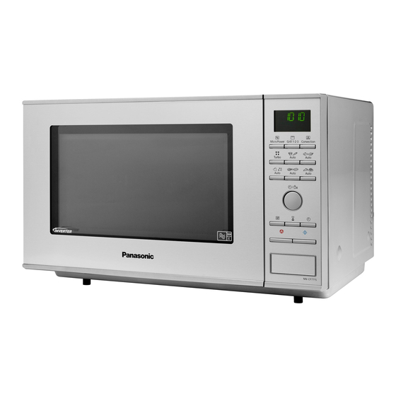
Page 1: Microwave Oven
ORDER NO.PHAMOS1101010CE Microwave Oven NN-CF771S BPQ (U.K.) EPG (Continental Europe) © Panasonic Home Appliances Microwave Oven (Shanghai) Co., Ltd. 2011... - Page 2 NN-CF771S...
- Page 3 NN-CF771S...
-
Page 4: Table Of Contents
NN-CF771S CONTENTS Page Page 1 FEATURE CHART 6.9. Convection fan motor and convection heater 2 CONTROL PANEL 7 COMPONENT TEST PROCEDURE 3 SCHEMATIC DIAGRAM 7.1. Primary, Secondary Latch Switch interlocks & Power 4 DESCRIPTION OF OPERATING SEQUENCE Relay RY1 4.1. Variable power cooking control 7.2. -
Page 5: Feature Chart
NN-CF771S 1 FEATURE CHART 2 CONTROL PANEL... -
Page 6: Schematic Diagram
NN-CF771S 3 SCHEMATIC DIAGRAM... -
Page 7: Description Of Operating Sequence
NN-CF771S 4 DESCRIPTION OF OPERATING SEQUENCE 4.1. Variable power cooking 4.3. Auto Menu cooking control When the Auto Menu feature is selected and the [Start] button is tapped: High Voltage Inverter Power Supply (U) controls output power 1. The digital programer circuit determines the power level and by the signal from Digital Programmer Circuit (D.P.C.). -
Page 8: Convection & Grill Convection Cooking Control
NN-CF771S 4.5. Convection & Grill Convection cooking control The digital programmer circuit controls the ON-OFF time of the heater in order to control oven cavity temperature. 1. After selecting desired oven cavity temperature Convection/Grill Convection (the range of selected oven temp is 100°C-250°C) and pressing [Start] button, a high... -
Page 9: Cautions To Be Observed When Troubleshooting
NN-CF771S 5 CAUTIONS TO BE OBSERVED WHEN TROUBLESHOOTING Unlike many other appliances, the microwave oven is a high voltage, high current device. It is free from danger in ordinary use, though extreme care should be taken during repair. CAUTION Servicemen should remove their watches & rings whenever working close to or replacing the magnetron. -
Page 10: Part Replacement
NN-CF771S 5.6. Verification after repair Discharging the high voltage capacitors WARNING 1. After repair or replacement of parts, make sure that the There is high voltage present with high current capabilities screws of the oven, etc. are neither loosen or missing. -
Page 11: Disassembly And Parts Replacement Procedure
NN-CF771S 6 DISASSEMBLY AND PARTS REPLACEMENT PROCEDURE 6.1. Inverter power supply 5. Release locking tabs connecting inverter air guide with inverter bracket. CAUTIONS 6. Remove 1 screw holding H.V.Inverter to Inverter bracket. 1. Always leave the grounding plate in place. -
Page 12: Magnetron
NN-CF771S 6.3. Digital programmer circuit 6.2. Magnetron (D.P.C) 1. Steps same as disassembly of H.V. Inverter step 1 to step NOTE: 2. Remove 1 screw holding thermistor on magnetron. Be sure to ground any static electric charge built up on your body before handling the D.P.C. - Page 13 NN-CF771S 3. Remove 2 screws holding D.P.C. board DU (Relay board). 6. Separate D.P.C board from tabs on the escutcheon base and remove D.P.C board. 4. Remove flat cable from CN13 on D.P.C board DU by pulling it out slightly.
-
Page 14: Low Voltage Transformer And/Or Power Relays (Ry1, Ry2, Ry4, Ry6)
NN-CF771S 6.4. Low voltage transformer 6.5. Fan motor and/or power relays (RY1, 1. Disconnect 2 lead wires from fan motor terminals. RY2, RY4, RY6) 2. Remove 4 screws holding inverter reinforcement bracket A on right heater panel & base plate respectively. -
Page 15: Quartz Heater
NN-CF771S 6.7. Door assembly 6.6. Quartz heater 1. Remove door C from door E by carefully pulling outward, 1. Disconnect lead wires from heater terminals. starting from upper right hand corner using a flat blade 2. Remove 2 screws holding heater mounting plate from the screwdriver. -
Page 16: Stirrer Motor
NN-CF771S 6.8. Stirrer motor 1. Remove the motor cover by breaking off at the 8 spots indicated by arrows with a cutter or the like. 6.9. Convection fan motor and convection heater 1. Remove 1 screw holding side cover on cavity back plate. - Page 17 NN-CF771S 4. Remove 1 screw holding back cover on the lower of back plate, then remove back cover. To replace convection heater 7. Remove 1 nut holding convection fan, then remove 5. Disconnect 4 lead wires from 2 thermal cutouts and convection fan.
- Page 18 NN-CF771S 9. Remove 1 screw holding heater bracket A on convection inside cover A. 10. Remove 2 screws holding convection heater on convection inside cover A. To replace convection motor 11. Remove 2 screws holding convection motor on convection fan bracket.
-
Page 19: Component Test Procedure
NN-CF771S 7 COMPONENT TEST PROCEDURE WARNING 7.3. Magnetron 1. High voltage is present at the output terminals of the High Voltage Inverter (U) including aluminum heat sink during any cook cycle. Continuity checks can only indicate an open filament or a 2. -
Page 20: Inverter Power Supply (U)
NN-CF771S 7.4. Inverter power supply (U) d. Press Micro Power button once. DO NOT try to REPAIR H.V. Inverter power supply 5. Program oven at High power for 1 minute and press [Start] (U).Replace complete H.V. Inverter(U) Unit. button. a. After approximately 3 seconds, oven stops operating. -
Page 21: Measurements And Adjustments
NN-CF771S 8 MEASUREMENTS AND ADJUSTMENTS 8.1. Adjustment of primary latch 8.2. Measurement of microwave switch, secondary latch switch output and short switch. The output power of the magnetron can be determined by performing IEC standard test procedures. However,due to the 1. -
Page 22: Troubleshooting Guide
NN-CF771S 9 TROUBLESHOOTING GUIDE DANGER: HIGH VOLTAGES 1. DO NOT RE-ADJUST PRESET CONTROL on the H.V.Inverter (U). It is very dangerous to repair or adjust without proper test equipment because this circuit generates very large current and high voltage. Operating a misaligned inverter circuit is dangerous. -
Page 23: Troubleshooting) Oven Stops Operation During Cooking
NN-CF771S 9.1. (Troubleshooting) Oven stops operation during cooking SYMPTOM CAUSE CORRECTIONS 1. Oven stops in 3 seconds after No input AC is supplied to H.V.Inverter (U) 1. Latch Switch pressing [Start] button. CN702 terminals 2. Power relay RY1 3. Loose lead wire connector CN701, CN702 4. -
Page 24: Troubleshooting) Other Problems
NN-CF771S 9.2. (Troubleshooting) Other problems SYMPTOM CAUSE CORRECTIONS 1. Oven is dead. 1. Open or loose lead wire harness Fuse is OK. 2. Open thermal cutout / thermistor Check thermal cutout is defective. No display and no operation at all. -
Page 25: Troubleshooting Of Inverter Circuit (U) And Magnetron
NN-CF771S 9.3. Troubleshooting of inverter circuit (U) and magnetron This oven is programmed with a self diagnostics failure code system which will help for troubleshooting. H95, H97, H98 and H99 are the provided failure codes to indicate magnetron and inverter circuit problem areas. This section explains failure codes of H95, H97, H98 and H99. -
Page 26: Simple Way Of H.v. Inverter/Magnetron Troubleshooting
NN-CF771S 9.4. Simple way of H.V. Inverter/magnetron troubleshooting Purpose: Simple way (3/23 seconds rule) of identifying whether it’s Magnetron, Inverter, or others. Set-up: The unit under question is connected through the Ammeter as shown below. Procedure: Follow the matrix table below to identify the problem source. -
Page 27: Inverter Main Parts List (F606Y6Y40Bp)
NN-CF771S 9.6. H.V. INVERTER MAIN PARTS LIST (F606Y6Y40BP) Ref. No. Part No. Part Name & Description Pcs/Set Remarks Q701 Z691EM300GP IGBT Q702 IGBT C701 Z0C2H184A013 FILM CAPACITOR C702 Z0C2E505A262 FILM CAPACITOR C703 Z0C2E395A246 FILM CAPACITOR DB701 Z0FBBQ000007 RECTIFIER BRIDGE L701... -
Page 28: Exploded View And Parts List
NN-CF771S 10 EXPLODED VIEW AND PARTS LIST 10.1. EXPLODED VIEW... -
Page 29: Parts List
NN-CF771S 10.2. PARTS LIST NOTE: 1. When ordering replacement part(s), please use part number(s) shown in this part list. Do not use description of the part. 2. Important safety notice: Components identified by mark have special characteristics important for safety. - Page 30 NN-CF771S Ref. No. Part No. Part Name & Description Pcs/Set Remarks Z41594V00BP COOLING FAN BLADE Z41809M60BP CONVECTION FAN BRACKET Z490S6Y40XP CONVECTION FAN MOTOR Z631D7Q70BP CONVECTION HEATER Z631D7Q80EP CONVECTION HEATER Z64174V00BP HEATER BRACKET A Z66797Q70BP CONVECTION INSIDE COVER Z22429M60BP ADIABATIC MATERIAL...
-
Page 31: Escutcheon Base Assembly
NN-CF771S 10.3. ESCUTCHEON BASE ASSEMBLY Ref. No. Part No. Part Name & Description Pcs/Set Remarks Z603L9M60BP D.P.CIRCUIT (AU) CF771S BPQ Z603L9M60EP D.P.CIRCUIT (AU) CF771S EPG Z603Y9M60BP D.P.CIRCUIT (DU) Z630N9N00SBP SUS COVER (U) CF771S BPQ Z630N9N00SEP SUS COVER (U) CF771S EPG... -
Page 32: Door Assembly
NN-CF771S 10.4. DOOR ASSEMBLY Ref. No. Part No. Part Name & Description Pcs/Set Remarks Z30186P40AG DOOR KEY A Z302A9N00SBP DOOR A (U) CF771S BPQ Z302A9N00SEP DOOR A (U) CF771S EPG Z301P9M60BP DOOR E (U) Z30215G10XN DOOR KEY SPRING Z30859Q30AP DOOR C... -
Page 33: Wiring Materials
NN-CF771S 10.5. WIRING MATERIALS Ref. No. Part No. Part Name & Description Pcs/Set Remarks Z030A9M60BP LEAD WIRE HARNESS Z030E-1P00 H.V.LEAD WIRE Z03877R00SP LEAD WIRE HARNESS U... -
Page 34: Packing And Accessories
NN-CF771S 10.6. PACKING AND ACCESSORIES Ref. No. Part No. Part Name & Description Pcs/Set Remarks Z00039N00BP INSTRUCTION MANUAL CF771S BPQ Z00039N00EP INSTRUCTION MANUAL CF771S EPG Z01029N00SEP PACKING CASE,PAPER Z01049M60BP UPPER FILLER Z01059M60BP LOWER FILLER Z01066Y40XP P.E.BAG Z01078100XN DOOR SHEET Z060V9M60BP... -
Page 35: Digital Programmer Circuit
NN-CF771S 11 DIGITAL PROGRAMMER CIRCUIT 11.1. SCHEMATIC DIAGRAM... - Page 36 NN-CF771S 01/11 S-9N0 Printed in China...