Table of Contents
Advertisement
Advertisement
Table of Contents

Related Manuals for Zoom 5350


Summary of Contents for Zoom 5350
- Page 1 Cable Modem/Router with Wireless-N U S E R M A N U A L...
- Page 2 NOTICE This document contains proprietary information protected by copyright, and this Manual and all the accompanying hardware, software, and documentation are copyrighted. No part of this document may be photocopied or reproduced by mechanical, electronic, or other means in any form. The manufacturer does not warrant that the hardware will work properly in all environments and applications, and makes no warranty or representation, either expressed or implied, with respect to the quality, performance, merchantability, or fitness for a particular purpose of the software or documentation.
-
Page 3: Table Of Contents
CONTENTS OVERVIEW INSTALLING THE CABLE MODEM/ROUTER WITH WIRELESS-N SETTING WIRELESS SECURITY WPA/WPA2 Security .......................... 16 Setting Up Security Using WEP ......................18 STATUS MENU OPTIONS BASIC MENU OPTIONS ADVANCED MENU OPTIONS FIREWALL MENU OPTIONS PARENTAL CONTROL MENU OPTIONS WIRELESS MENU OPTIONS VPN MENU OPTIONS APPENDIX A: HOW TO SET UP A WIRELESS NETWORK... -
Page 4: Overview
Overview This User Manual provides instructions for connecting and configuring your Cable Modem/Router with Wireless-N and setting up wireless and wired local area networks. It also includes details about security, firewalls, VPNs (Virtual Private Networks) and administrative tasks. If you have used the Quick Start flyer to set up your cable modem/router, establish an Internet connection, and set up your local area network, you may choose to reference this User Manual for advanced topics or to make changes to the settings you previously configured. - Page 5 Chapter Menu Go to this section if you Page Options want to… troubleshoot problems with Status the cable modem/router make some modifications Basic for more advanced uses make use of advanced router Advanced features supported by the cable modem/router configure the firewall application to protect the Firewall private LAN from attacks...
- Page 6 automatically opening up the corresponding incoming port(s). It will automatically forward the traffic on the incoming port to the computer that accessed the outgoing port. If your game uses one port to send outgoing data and a different port (or ports) for incoming data, you may want to use port triggering.
-
Page 7: Package Contents
Installing the Cable Modem/Router with Wireless-N This chapter provides basic instructions for connecting the hardware and configuring the Cable Modem/Router with Wireless-N using the Zoom Configuration Manager. This chapter is almost identical to the printed Quick Start. Package Contents Your package contains the following items: •... - Page 8 Your cable service provider may also ask for your cable modem’s model name and number, which is Zoom 5350. You will need to plug in the cable modem/router’s power cord, connect to cable modem service using a coaxial cable, and then connect to a computer using either the included Ethernet cable or the wireless feature (see Using the Cable Modem/Router to Make a Wireless Connection).
- Page 9 1 Be sure your computer is on and the cable modem/router is unplugged. Note: Please refer to the Hardware Connection section if you would like to see a diagram of the back of the cable modem and a description of the connections as you read the following steps.
- Page 10 Please note the following: • Do not block the modem/router vents in any way. • Do not use the modem where it’s very hot or very cold. • Place the cable modem/router in a vertical orientation (using the “feet” at the bottom of the unit to create a stable placement).
- Page 11 Windows taskbar. A list of available networks is displayed. Click ZOOM (or the SSID you changed the default to), and then click Connect. You may see a screen with a text box for the Security key. If WPS configuration is supported, you may see a message such as You can also connect by pushing the button on the router.
- Page 12 Press the Wi‑Fi Protected Setup (WPS) button on the router for 5 seconds. (You do not need to type a security key or passphrase in the Security key text box on your Windows machine). The cable modem/router will automatically set up the computer to connect to the network and apply the network's security settings.
- Page 13 Note: If at any time you need to make changes to the cable modem/router’s configuration, open a web browser from any PC on your cable modem/router’s network and type http://192.168.0.1 to open the Zoom Configuration Manager. Alternately, you can connect a computer directly to the cable modem/router, open its browser, and then type http://192.168.0.1.
-
Page 14: Troubleshooting Tips
Tips. From the Zoom Configuration Manager, you can configure advanced features and make changes to the default wireless security options including the SSID and Pre-Shared Key. If you want to change the default SSID or Pre-Shared Key, go to... -
Page 15: Setting Wireless Security
Setting Wireless Security Your cable modem/router comes from the factory with, security turned on by default. If you want to use another security mode instead of the default security mode of WPA-PSK/WPA2-PSK , or if you want to change the Pre-Shared Key, this chapter explains how. ... -
Page 16: Wpa/Wpa2 Security
If you know that all your devices support the more secure WPA2 you can enable WPA2 only instead of both WPA and WPA2. 1 Open the Zoom Configuration Manager by typing the following in your Web browser's address bar: http://192.168.0.1 2 In the Enter Network Password dialog box, type the following User Name and Password in lower case, then click OK.. - Page 17 Select the Site Survey or Scan option to see a list of the access points in your area. That list should include the SSID ZOOM or the SSID you created. d Select ZOOM (or the SSID you created).
-
Page 18: Setting Up Security Using Wep
WEP can be configured two ways: 64-bit and 128-bit. 128-bit WEP provides more security than 64-bit. 1 Open the Zoom Configuration Manager by typing the following in your Web browser's address bar: http://192.168.0.1 2 In the Enter Network Password dialog box, type the following User Name and Password in lower case, then click OK.. - Page 19 If for some reason you need to set up an unsecured network, you will need to disable the default security that is currently set up for your cable modem/router. Follow the instructions below. Open the Zoom Configuration Manager by typing the following in your Web browser's address bar: http://192.168.0.1 In the Enter Network Password dialog box, type the following User Name and Password in lower case, then click OK..
- Page 20 Select the Site Survey or Scan option to see a list of the access points in your area. That list should include the SSID ZOOM or the SSID you created. d Select ZOOM (or the SSID you created).
- Page 21 Chapter Menu Go to this section if you Options Page want to… monitor or troubleshoot Status problems with the cable modem/router make some modifications Basic for more advanced uses make use of advanced router Advanced features supported by the cable modem/router configure the firewall application to protect the Firewall...
- Page 22 In the Login screen, enter: default username: admin default password: admin Both the username and password are case sensitive. After you log in to the Zoom Configuration Manager interface, you can change the default password on the Status - Security page. ...
- Page 23 Click the Login button to access the cable modem/router. The Status page appears, showing connection status information about your cable modem/router. Understanding the Configuration Manager Interface Screens The top of the management interface contains a menu bar you use to select menus for configuring the cable modem/router.
- Page 24 Figure 3. Example of Status Submenu The right-most item on the menu bar is the logout option. Click it to log out from the Configuration Manager interface. Configuration Manager Interface Menus Table 1 describes the menus in the Configuration Manager interface. Table 1.
-
Page 25: Status Menu Options
Status Menu Options The Status Menu lets you: View the status and connection information of the cable modem/router Change the administrator password Use diagnostic tools for troubleshooting Software The Software page is a read-only screen that shows the cable modem/router’s current system software version. - Page 26 Figure 4. Software Menu Table 2. Software Menu Option Option Description Information Shows the information on the current system software. Shows the system up time, network accessibility, and IP address of the Cable Status modem/router. Connection The Connection page is a read-only screen that shows the status of steps in your cable modem/router registration process.
- Page 27 Figure 5. Example of Connection Page Security The Security page allows you to configure access privileges and restore the cable modem/router to its factory defaults. To access the Security page, click Status in the menu bar and then click the Security submenu. Figure 6 shows an example of the menu and Table 3 describes the items you can select.
- Page 28 Figure 6. Example of Security Page To restore the cable modem/router to factory defaults: In the Security submenu, select the Yes button next to Restore Factory Defaults. Click Apply. Click OK to reboot the cable modem/router. The reboot is complete when the POWER LED stops blinking.
- Page 29 Diagnostics Note: Some versions may not support this feature. The Diagnostics page allows you to troubleshoot connectivity problems. Two utilities are provided for troubleshooting network connectivity: Ping and Traceroute. Ping allows you to check connectivity between the cable modem/router and devices on the LAN while Traceroute allows you to map the network path from the cable modem/router to a public host.
- Page 30 Table 4 describes the items you can select. Figure 7. Example of Diagnostics - Ping Page ...
- Page 31 Figure 8. Example of Diagnostics - Traceroute Page To run either utility: Select the utility from the Utility drop-down list. Make any changes to the default parameters. Select Start Test to begin. The window will automatically be refreshed as the results are displayed in the Results table.
- Page 32 Table 4. Diagnostics Menu Option Option Description Utility Select the utility for troubleshooting. Parameters Enter the required parameters to perform diagnostics. Click this button to begin diagnostic after making any changes to the default Start Test parameters. Abort Test Click this button to abort Ping diagnostics. Clear Results Click this button to clear the results table.
-
Page 33: Basic Menu Options
Basic Menu Options The Basic Menu lets you: Configure the basic settings of your cable modem/router Configure DHCP server for the LAN Configure DDNS service Backup and restore of configuration settings Setup The Setup page allows you to configure the basic features of the cable modem/router related to your ISP’s connection. - Page 34 Figure 10. Example of Setup Page Table 6. Setup Menu Option Option Description Set the base LAN IP for your private network. By default this is 192.168.0.1 LAN IP Address There is normally no need to change this. Select how your cable modem/router obtains an IP address. The options are via DHCP or manual configuration of a static IP address.
- Page 35 DHCP The DHCP page allows you to configure your cable modem/router’s DHCP server. To access the DHCP page: Click Basic in the menu bar. Then click the DHCP submenu. Figure 11 shows an example of the menu and Table 7 describes the items you can select. Figure 11.
- Page 36 In the unusual event that you have a separate DHCP server on your LAN, you can disable the cable modem/router’s DHCP server by selecting the No radio button. If you do this, make sure the IP address assigned to the cable modem/router is on the same subnet as that of the external DHCP server, or you won’t be able to access the cable modem/router from the LAN.
- Page 37 Figure 12 shows an example of the menu and Table 8 describes the items you can select. Figure 12. Example of DDNS Page To activate the DDNS client: Go to the DynDNS website and create an account for the Dynamic DNS service. You will create a username and password, and be asked to choose a host name for your server, and the dynamic DNS domain to which your host will be assigned.
- Page 38 Table 8. DDNS Menu Option Option Description Select the type of service that you are registered for from your DDNS service DDNS Service provider. User Name Enter your DDNS account username subscribed to the service provider. Password Enter the password of the account. Host Name Enter the host name of your service host.
- Page 39 Figure 13. Example of Backup Page ...
-
Page 40: Advanced Menu Options
Advanced Menu Options The Advanced Menu lets you: Enable advanced features of the cable modem/router Configure LAN IP address, MAC address, and port number filtering Configure WAN to LAN port forwarding and triggers Configure DMZ hosting Configure RIP parameters Options The Options page allows you to configure the cable modem/router to operate in different modes that adjust how the device routes IP traffic. - Page 41 Figure 14. Example of Options Page To enable a feature: Click the appropriate check box (a check mark will appear). When you are done with your selections, click on the Apply button. ...
- Page 42 Table 9. Options Menu Option Option Description Prevents the cable modem/router or the PCs behind it from being visible to the WAN (i.e. from the Internet). For instance, pings to the cable WAN Blocking modem/router’s WAN IP address or to the devices behind it are not returned.
- Page 43 IP Filtering The IP Filtering page allows you to configure IP address filters in order to block Internet traffic to specific network device on your LAN. By entering starting and ending IP address ranges, you can configure which local PCs are denied access to the WAN. To access the IP Filtering page: Click Advanced in the menu bar.
- Page 44 To activate the IP address filter: Enter the last byte (the numbers after the last period) of the IP address in Start Address and End Address. Check the Enable box to the right of the entry to store settings. Click the Apply button to activate the filter rules. Table 10.
- Page 45 Figure 16. Example of MAC Filtering Page Table 11. MAC Filtering Menu Option Option Description PCs and other devices can be added to the MAC filter table by entering their MAC addresses into the Add MAC Address box, and clicking the Add MAC MAC Address Address button.
- Page 46 Port Filtering The Port Filtering page allows you to configure port filters in order to block Internet traffic to specific ports on all devices on your LAN. Similarly, you can prevent PCs from sending outgoing TCP/UDP traffic to the Internet from specific IP port numbers.
- Page 47 For example, if you would like to block all PCs on the private LAN from accessing HTTP sites (or “web surfing”): Set the Start Port to 80, the End Port to 80. Set the protocol to TCP. Check the Enable box to the right of the entry to store settings. Click Apply button to activate the filter rules.
- Page 48 Figure 18. Example of Forwarding Page To activate the port forwarding: Enter the port range of the Internet traffic that you want to forward, and the IP address of the server to which you want to forward that traffic. Select the protocol(s) to be forwarded. Check the Enable box to the right of the entry to store settings.
- Page 49 Port Triggers The Port Triggers page allows you to configure dynamic triggers to specific devices on the LAN. This allows for special applications that require specific port numbers with bi-directional traffic to function properly. Applications such as video conferencing, voice, gaming, and some messaging program features may require these special settings.
- Page 50 Check the Enable box to the right of the entry to store settings. Click the Apply button to activate the forwarding rules. Table 14. Port Triggers Menu Option Option Description Trigger Range Enter the trigger range (starting and ending ports) of the application for which you want to enable port triggering.
- Page 51 Figure 20. Example of DMZ Host Page To configure DMZ settings: Enter the last byte of the LAN IP address of the PC or other device on your network that you want to configure as a DMZ host. Click Apply. Note: If a specific PC is set as a DMZ Host, remember to set this back to “0”...
- Page 52 Figure 21. Example of RIP Setup Page Note: RIP messages will only be sent when the cable modem/router is configured for Static IP Addressing (see the Basic – Setup page). It is unlikely that your cable Internet service supports this mode. If they do, and you want to enable RIP, you will need to ask for the CMTS’s key name and number.
- Page 53 Table 15. RIP Setup Menu Option Option Description Check this box to enable RIP authentication for routing RIP Authentication protocols RIP Authentication Key Enter the set of keys for your interface. Enter the ID to identify the key used to create the RIP Authentication Key ID authentication data.
-
Page 54: Firewall Menu Options
Firewall Menu Options The Firewall Menu lets you: Configure web contents filter View the local and remote logs Web Filter The Web Filter page allows you to block or exclusively permit different types of data through the cable modem/router from the WAN to the LAN. To access the Web Filter page: Click Firewall in the menu bar. - Page 55 Figure 22. Example of Web Filter Page To enable web content filter: Click the appropriate check box. A check-mark will appear. When you are done with your selections, click on the Apply button. Table 16. Web Filter Menu Option Option Description Filter Proxy Check this box to filter proxies.
- Page 56 Block Fragmented IP Prevents all fragmented IP packets from passing through packets the firewall. Detects and blocks packet floods originating on both the IP Flood Detection LAN and WAN. Turns on the Stateful Packet Inspection (SPI) firewall Firewall Protection features. Note: Java applets, ActiveX controls, and popup windows function filtering will fail if the web pages are sent in uncompressed format to the web browser.
- Page 57 Figure 23. Example of Remote Log Page Table 17. Local Log Menu Option Option Description Contact Email Enter the email address where you want to receive the alert email. Address SMTP Server Enter the SMTP (Outgoing) mail server address of the email account you will Name send from.
- Page 58 To access the Remote Log page: Click Firewall in the menu bar. Then click the Remote Log submenu. Figure 24 shows an example of the menu and Table 18 describes the items you can select. Figure 24. Example of Remote Log Page Below is a complete list of the capable SysLog server attack/notification types and their format.
- Page 59 Table 18. SysLog Server Event Format Parameter Description The three-letter abbreviation for the month (e.g., JUN, JUL AUG, etc.) The two-digit day of the month (e.g., 01, 02, 03, etc.) The time displayed as two-digit values for the hour, minute, and second, HH:MM:SS respectively.
- Page 60 The table below lists all events that can be sent to the SysLog server. Table 19. SysLog Server Event and Meaning Event Text Meaning An inbound request was made, and accepted, from a public ALLOW: Inbound access network client to use a service hosted on the firewall or a client request behind the firewall.
- Page 61 The system established the current system time via the DOCSIS Time Of Day established cable modem registration process. The system time is used by the firewall to timestamp events. The firewall successfully obtained an IP address for the public Public Network Interface up network (WAN) interface via DHCP.
-
Page 62: Parental Control Menu Options
Parental Control Menu Options The Parental Control Menu lets you: Configure the rules for Internet access based on user or time period Configure the rules to block certain Internet contents and certain web sites View the event logs related to parental control To set up Parental Control, you first set up Policies in the Basic Setup Menu. - Page 63 Figure 25. Example of Basic Page ...
- Page 64 Table 20. Basic Setup Menu Option Option Description Enable Parental Check the box to enable Parental Control. Control Content Policy Enter a name for a content policy, and click Add New Policy. Configuration Enter a keyword in the field at the bottom of the keyword list, and click Add Keyword.
- Page 65 User Setup The User Setup page is the master page to which each individual “user” is linked to a specified time access rule, content filtering rule, and login password. To access the User Setup page: Click Parental Control in the menu bar. Then click the User Setup submenu.
- Page 66 Table 21. User Setup Menu Option Option Description User Enter a user name (e.g. Mom, Dad, Bro, Sis) and click Add User. Configuration Select a user from the drop-down list. Click the checkbox to enable parental Users Settings control for this user. Password Enter the password for this user.
- Page 67 ToD Filter (Time of Day Filter) The ToD page allows you to configure the Internet access policies according the time of day settings. This page is tied to the Parental Control - User Setup page. You can define up to 30 time access policies.
- Page 68 Table 22. ToD Filter Menu Option Option Description Enter a name for the time access policy and click Add Time Access Policy Configuration New Policy. Select a policy from the drop-down list. Click the Enable Time Access Policy List checkbox to enable this rule. Days to Block Click the checkboxes of the days that this rule applies to.
- Page 69 To access the Local Log page: Click Parental Control in the menu bar. Then click the Local Log submenu. Figure 28 shows an example of the menu. Figure 28. Example of Local Log Page ...
-
Page 70: Wireless Menu Options
Wireless Menu Options The Wireless Menu lets you: Configure cable modem/router to serve as a wireless access point (AP) Configure essential and advanced settings of wireless network Configure guest network for temporary visitors Configure WMM QoS Note: Your cable modem/router has been preconfigured to support wireless connections without any further configuration. - Page 71 Figure 29. Example of Radio Page ...
- Page 72 Table 23. Radio Menu Option Option Description Wireless Select Enable to enable the wireless function. Country Your device is configured for operation in the U.S. only. Set the strength of the wireless signal that the cable modem/router Output Power transmits. 802.11 Band Your device supports 2.4 GHz only.
- Page 73 automating the processes of configuring new wireless networks and adding devices to existing networks. • SES establishes a private connection between the devices and automatically configures the network's SSID and WPA-Personal security settings. It configures a new network only on each new device that is authorized to join the network.
- Page 74 Table 25. Primary Network Menu Option Option Description Primary Network Select Enable to enable primary wireless network. Set the Network Name (also known as SSID) of the wireless Network Name (SSID) network. This is a 1-32 ASCII character string. Closed Network Select Enable to suppress broadcast of the SSID.
- Page 75 802.1x Authentication (only available when WEP is Select Enable to enable 802.1x authentication. enabled) You can pre-define up to 4 keys for 64-bit or 128-bit WEP. 64-bit Network Key 1-4 keys require 10 hexadecimal digits and 128-bit key require 26 hexadecimal digits.
- Page 76 Figure 31. SES Configuration Window - Success! Open SES Window This button opens a window that allows a SES client to connect. The window remains open for 2 minutes. Only 1 SES client may connect during an Open Window period. If you have more than 1 client to connect to your SES, you must open the window multiple times.
- Page 77 Figure 34. SES Configuration Window - Timeout! Finally, if the current security configuration does not meet the SES requirements of WPA-PSK authentication with TKIP, the window will not open and the error message shown below will be displayed. Figure 35. Authentication Error Message Guest Network The Guest Network page allows you to configure a guest network.
- Page 78 Figure 36 shows an example of the menu and Table 26 describes the items you can select. Figure 36. Example of Guest Network Page ...
- Page 79 Table 26. Guest Network Menu Option Option Description Guest Network Select Enable to enable guest network. Guest Network Name Enter a name for the guest network. (SSID) Closed Network Select Enable to supress broadcast of the SSID. WiFi Protected Access (WPA) offers stronger encryption than WEP.
- Page 80 802.1x Authentication (only available when WEP is Select Enable to enable 802.1x authentication. enabled) You can pre-define up to 4 keys for 64-bit or 128-bit WEP. 64-bit Network Key 1-4 keys require 10 hexadecimal digits and 128-bit key require 26 hexadecimal digits.
- Page 81 Figure 37. Example of Advanced Page ...
- Page 82 Table 27. Advanced Menu Option Option Description Mode Auto by default. Select the wireless transmission rate to a particular speed or leave it Basic Rate Set as default (Auto) to allow the AP adjusts speed automatically. In Auto mode (Protection ON), the device will use RTS/CTS control to improve 802.11g performance in mixed networks.
- Page 83 there is a possibility that 802.11b or 802.11g devices will use your wireless network. In Auto mode, the wireless devices use RTS/CTS to improve 802.11n performance in mixed 802.11g/802.11b networks. Turn protection off to maximize 802.11n throughput under most conditions. Specify the rate at which multicast packets are transmitted and received on your wireless network.
- Page 84 Table 28. Access Control Menu Option Option Description Wireless Select the wireless interface to configure the access control list. Interface MAC Restrict Select whether wireless clients with the specified MAC address are allowed or Mode denied wireless access. To allow all clients, select Disabled. Shows the list of wireless client MAC addresses to allow or deny based on MAC Addresses the Restrict Mode setting.
- Page 85 Figure 39. Example of WMM Page ...
- Page 86 Table 29. WMM Menu Option Option Description WMM Support Select On to include the WME Information Element in beacon frame. No-Acknowledgement Select On to not transmit acknowledgments for data. Select On to allow the AP (cable modem/router) queuing packets for Power Save Support stations/clients in power-save mode.
- Page 87 Figure 40. Example of Bridging Page Table 30. Bridging Menu Option Option Description Wireless Bridging Select to enable or disable wireless bridging. Table of remote bridge MAC addresses authorized to establish a wireless Remote Bridges bridge. Up to 4 remote bridges may be connected. Typically, you will also have to enter your AP’s MAC address on the remote bridge.
- Page 88 VPN (Virtual Private Network) Menu Options The VPN Menu lets you: Configure a VPN tunnel View VPN event logs Basic Setting This page allows you to enable VPN protocols and manage VPN tunnels. A virtual private network (VPN) is a computer network in which some of the links between nodes are carried by open connections or virtual circuits within some larger network (e.g., the Internet) as opposed to by physical wires, as in a traditional private network.
- Page 89 Table 31. Basic Menu Option Option Description L2TP Server Select Enable to enable L2TP (Layer 2 Tunneling Protocol) server. PPTP Server Select Enable to enable PPTP (Point-to-Point Tunneling Protocol) server. IPSec Endpoint Select Enable to enable IPSec endpoint. IPSec The IPSec page allows you to configure IPSec tunnel and endpoint settings. A VPN tunnel is usually established in two phases.
- Page 90 To access the IPSec page: Click VPN in the menu bar. Then click the IPSec submenu. Figure 42 shows an example of the menu and Table 32 describes the items you can select. Figure 42. Example of IPSec Page ...
- Page 91 Table 32. IPSec Menu Option Option Description This is a pull-down list of VPN Names defined below. Select the specific Tunnel VPN tunnel to configure. Name Enter a VPN name and click Add New Tunnel. Local Endpoint Configure the local network located at your cable modem/router’s AN Settings side.
- Page 92 Select the Diffie-Hellman key group (DHx) you want to use for encryption keys. DH1: uses a 768-bit random number Phase 1DH Group DH2: uses a 1024-bit random number DH5: uses a 1536-bit random number. Select the key size and encryption algorithm to use for data communications.
- Page 93 Select the key size and encryption algorithm to use for data communications. Null: No data encryption in IPSec SA. Not recommended. DES: a 56-bit key with the DES encryption algorithm 3DES: a 168-bit key with the DES encryption algorithm. Both the cable modem/router and the remote IPSec router must use the same Phase 2 Encryption algorithms and key , which can be used to encrypt and decrypt the...
- Page 94 Select Enable to send NetBIOS (Network Basic Input/Output System) packets through the VPN connection. NetBIOS packets are TCP or NetBIOS Broadcast UDP packets that enable a computer to find other computers. It may Forwarding sometimes be necessary to allow NetBIOS packets to pass through VPN tunnels in order to allow local computers to find computers on the remote network and vice versa.
- Page 95 Figure 43. Example of L2TP/PPTP Page ...
- Page 96 Table 33. L2TP/PPTP Menu Option Option Description Configure the dedicated IP address pool for L2TP/PPTP. The LAN IP subnet at one end of the VPN tunnel must be different from the LAN PPP Address Range IP subnet at the other end of the VPN tunnel. For example, if one (Start/End) side’s LAN subnet is 192.168.0.x, then the other side should be 192.168.1.x (where the subnet mask in this example is 255.255.255.0).
- Page 97 Figure 44. Example of Event Log Page Table 34. Event Log Menu Option Option Description Time Shows the local time mapping to a certain log event. Description Shows detailed information of a VPN event log. ...
- Page 98 1 From the notification area of the Windows taskbar, click on the wireless symbol. 2 In the wireless network options box, highlight ZOOM (or the SSID you changed it to) and click Connect. (The cable/modem router comes set up with default security. The default security mode is WPA-PSK/WPA2-PSK.
- Page 99 1 From the Start menu select Connect to. 2 In the Connect to a network dialog box, highlight ZOOM (or the SSID you changed it to) and click Connect. (The cable/modem router comes set up with default security. The default security mode is WPA-PSK/WPA2-PSK.
- Page 100 Available networks list. It should find the wireless network of the Cable Modem/Router—named ZOOM (or the SSID you changed it to). (The scan is done automatically because the Use Windows to configure my wireless network settings check box is selected by default).
- Page 101 5 Select ZOOM (or the SSID you changed it to) from the Available networks list, then click the Configure button to add it to the Preferred networks list. The notebook will try to connect to the Internet using the wireless networks listed here, in the order in which they appear. (If you already have networks listed here, we recommend you either remove them or use the Move up button to move ZOOM (or the SSID you changed it to) to the top of the list.) The...
- Page 102 By default, the Cable Modem/Router uses channel 10. If you need to change this channel, you must do so using the Wireless Setup page of the Zoom Configuration Manager. For instructions on how to log in to the Zoom Configuration Manager, see page 13. Then Chapter 8 for instructions on how to access the Wireless Setup page to change the channel.
- Page 103 Having less than a five-channel difference may result in interference with your connection. By default, the Cable Modem/Router uses channel 10. If you need to change this channel, you must do so using the Wireless Setup page of the Zoom Configuration Manager. For instructions on how to log in to the Zoom Configuration Manager, see page 13.
- Page 104 1 On your computer that has a wireless adapter, find the wireless network connection option (similar to the process of adding your computer to the network). 2 Click or highlight ZOOM (or the SSID you changed it to). 3 Select or click on Disconnect or similarly-named button.
-
Page 105: Appendix B: Troubleshooting Tips
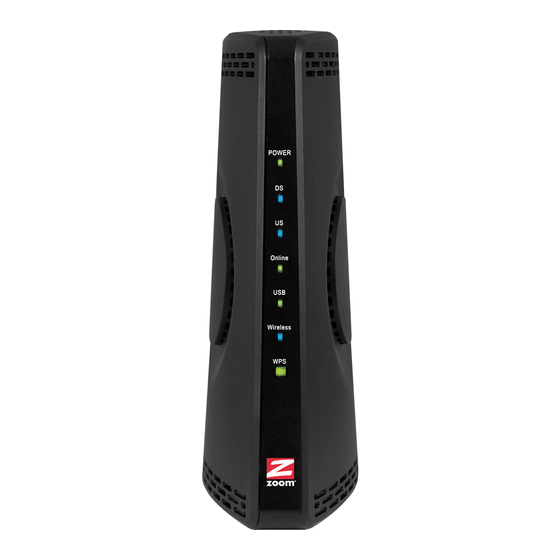
Appendix B: Troubleshooting Tips Problem: I cannot access my Internet service or send or receive email. Solution: The following front panel lights on the cable modem/router – ONLINE, US (upstream), DS (downstream), and POWER – must be solidly lit before your modem will let you connect to the Internet. -
Page 106: Appendix C: If You Need Help
We encourage you to register your product and to notice the many support options available from Zoom. Please go to www.zoomtel.com/techsupport. From here you can register your router and/or contact our technical support experts and/or use our intelligent database SmartFacts and/or get warranty information. -
Page 107: Appendix D: Compliance
Appendix D: Compliance FCC Interference Statement This equipment has been tested and found to comply with the limits for a Class B digital device pursuant to Part 15 of the FCC Rules. These limits are designed to provide reasonable protection against radio interference in a commercial environment. - Page 108 IMPORTANT NOTE: FCC Radiation Exposure Statement This equipment complies with FCC radiation exposure limits set forth for an uncontrolled environment. This equipment should be installed and operated with minimum distance 20cm between the radiator & your body. This transmitter must not be co-located or operating in conjunction with any other antenna or transmitter.
Need help?
Do you have a question about the 5350 and is the answer not in the manual?
Questions and answers