Table of Contents
Advertisement
Quick Links
Download this manual
See also:
Owner's Manual
Advertisement
Table of Contents

Related Manuals for Xantrex Xanbus System


Summary of Contents for Xantrex Xanbus System
- Page 1 Installation Guide Xanbus System...
- Page 3 Xanbus System Installation Guide...
-
Page 4: Contact Information
About Xantrex Xantrex Technology Inc. is a world-leading supplier of advanced power electronics and controls with products from 50 watt mobile units to one MW utility-scale systems for wind, solar, batteries, fuel cells, microturbines, and backup power applications in both grid-connected and stand-alone systems. Xantrex products include inverters, battery chargers, programmable power supplies, and variable speed drives that convert, supply, control, clean, and distribute electrical power. -
Page 5: About This Guide
About This Guide Purpose The purpose of this Guide is to provide explanations and procedures for planning and installing a Xanbus System. Scope The Guide provides planning and setup information and guidelines for installing the network. Audience The Guide is intended for anyone who needs to plan for a network and/or install a Xanbus System. -
Page 6: Conventions Used
Related Information Information about additional Xanbus-enabled products is available at www.xantrex.com. In order to complete network installation, you will also need to refer to the Installation, Operation, or Owner’s Guide for the Xanbus-enabled products you’ve purchased. -
Page 7: Table Of Contents
Connecting Your Xanbus System - - - - - - - - - - - - - - - - - - - - - - - - - - - - - - - - - - - -... - Page 9 Hibernate Mode - - - - - - - - - - - - - - - - - - - - - - - - - - - - - - - - - - - - - - - - - - - - - - - - - - 22 CAUTION: Equipment damage Connect the Xanbus System only to Xanbus compatible devices. Although the cabling and connectors used in this network system are the same as Ethernet connectors, this network is not an Ethernet system.
- Page 10 viii...
- Page 11 Installation The Installation Guide provides detailed information for planning and installing a Xanbus System.
-
Page 12: Xanbus-Enabled Devices
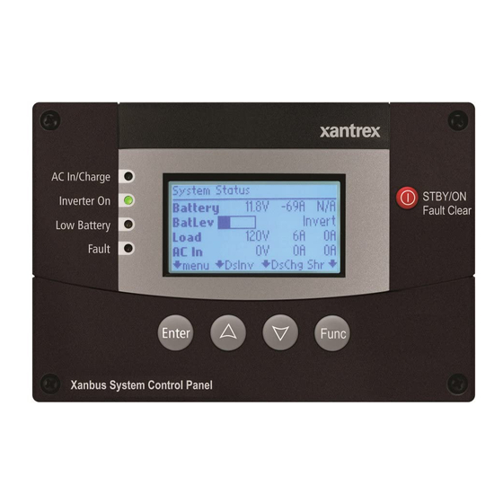
System Control Panel The System Control Panel provides configuration and monitoring capability for Xanbus-enabled devices. For complete information, see the user guide for your interface panel. For detailed instructions and a complete list of Xanbus-enabled devices, visit the website at www.xantrex.com. 975-0136-01-01... -
Page 13: The Xanbus System
Installation The Xanbus System What is a network? A network is a collection of devices that perform individual functions, but also communicate and interact with the other devices. The Xanbus System provides a robust, integrated product solution which simplifies and automates the installation, configuration, control, monitoring, and integration of devices that deliver and distribute AC or DC power. -
Page 14: Purchasing System Accessories
Installation Purchasing System Accessories System accessories are available from any authorized Xantrex dealer or at www.xantrex.com. Table 1 provides a partial list of system accessories. When ordering, please provide the part number of the accessory to the dealer. Table 1 System Accessories... -
Page 15: Planning The Network
See “Installing the Network” on page 11 for instructions on routing and layout. Network Layouts Xanbus-enabled devices can be connected in one of two Xanbus System layouts: the multi-drop backbone or the daisy chain. Each network layout has advantages and disadvantages, depending on the application and/or environment. -
Page 16: Daisy Chain Layout
With only one terminator, the signal quality is degraded and performance on the network is reduced. Permanent configuration with only one terminator is not supported by Xantrex. If cables are placed at the end of the network (as in Figure 2), female terminators are required. -
Page 17: Network Connectors, Terminators, And Cables
Installation Disadvantage The disadvantage of the daisy chain layout is that Xanbus-enabled devices cannot be removed from the network without interrupting the network. To make the network function after removing a device, you must connect the Xanbus-enabled devices on either side of the missing device to each other or replace the device. -
Page 18: Cabling Requirements
Cabling The network uses Category 5 (CAT 5) cable, a standard cable available from Xantrex or any computer supply store. The cable consists of eight conductors in four twisted pairs with an RJ45 modular connector wired to the T568A standard. Table 3 contains the arrangements of wire colors to pin numbers for the T568A standard. -
Page 19: Connector Requirements
8-contact for round, stranded, unshielded cable. Figure 6 RJ45 Connector Network Power Supply In a Xanbus System, the power sources must provide sufficient power for all of the Xanbus-enabled devices. Important: All networks, regardless of type, require a device that powers the network. -
Page 20: Network Size
Installation Network Size Table 4 summarizes the network size in terms of distances and cable lengths. Table 4 Minimum and Maximum Cable Length Cable Length Minimum Maximum Backbone or daisy chain 4 inches (10 cm) 130 feet (40 meters) Total backbone length or daisy chain 4 inches (10 cm) 130 feet (40 meters) Drop cable on backbone 4 inches (10 cm) -
Page 21: Installing The Network
Xantrex. Important: Installing and replacing Xanbus-enabled devices in an existing system must be performed with the Xanbus System in Safe mode. See “Putting the System in Safe Mode” on page 16. Before You Begin the Installation •... -
Page 22: Guidelines For Routing The Network Cables
Installation Guidelines for Routing the Network Cables WARNING: Shock hazard Do not route the network cables in the same conduit or panel as the AC and DC power cabling. To ensure maximum performance of your network, follow these guidelines when routing the network cables. Route the cables before installing Xanbus-enabled devices. -
Page 23: Mounting A Network Connector
Installation Mounting a Network Connector To mount a network connector: 1. Select an appropriate location with the connector in the recommended mounting orientation, as shown in Figure 7. Figure 7 Recommended Mounting Orientation for Network Connector 2. Mark the position of the mounting screws. 3. -
Page 24: Connecting Your Xanbus System
Installation Connecting Your Xanbus System Use an appropriate length of network cable to connect each device and 3- way network connector (if used). See Figure 2 on page 1–5 and Figure 3 on page 1–6. CAUTION: Equipment Damage Connect only to other Xanbus compatible devices. -
Page 25: Completing The Daisy Chain Layout
Installation Completing the Daisy Chain Layout To complete the daisy chain layout: Insert male terminators into the open network ports of the Xanbus- enabled devices at each end of the network. See Figure 9. Figure 9 Completing a Daisy-Chain Layout CAUTION: Unpredictable device behavior After connecting the Xanbus-enabled devices and terminating the network, do not plug terminators or other cables into any remaining open network ports on... -
Page 26: Putting The System In Safe Mode
Putting the System in Safe Mode CAUTION: Unpredictable device behavior Before removing or installing a device on an existing Xanbus System, you must put the system into Safe mode from the System Control Panel. In Safe mode, all Xanbus-enabled devices remain powered and continue to communicate, and all device outputs are disabled. -
Page 27: Figure 12 Safe Mode
Installation For more information on the different system modes (Operate, Power Save, and Hibernate), see “System Modes” on page 20. Figure 12 Safe Mode 5. Press Enter. You are now in Safe mode. 6. Press Exit twice to return to the System Home screen. To exit Safe mode: 1. -
Page 28: Testing Your Installation
Installation Testing Your Installation After you have installed the Xanbus System, you should confirm that your installation is operating correctly. Verifying Power is Available Each Xanbus-enabled device has an indicator light or display screen that confirms that it is receiving power. See the Installation or Owner’s Guide for each Xanbus-enabled device for information on verifying network power. -
Page 29: Figure 14 System Settings: View Device Info
Installation Figure 14 System Settings: View Device Info 5. Press Enter. 6. To view the Device Information screen for each device, press the down arrow button. 809-2000 442-0110-01-01 1.00.00 Figure 15 Device Information Screen (RS2000 used for example) 7. To return to the System Settings menu, press Exit. 975-0136-01-01... -
Page 30: System Modes
See the System Control Panel Owner’s Guide for complete information. The system modes described in this section affect the performance and behavior of all Xanbus-enabled devices on the Xanbus System. You can change system modes using the System Settings menu on the System Control Panel. -
Page 31: Operate Mode
The default mode of any Xanbus-enabled device is Operate mode. Whenever any device on the Xanbus System is powered on or reset, it will be in Operate Mode, as shown in Figure 17. Figure 17 Operate Mode Safe Mode See “Putting the System in Safe Mode”... -
Page 32: Hibernate Mode
Hibernate mode Characteristics Hibernate mode removes power from all Xanbus-enabled devices on the Xanbus System. All operations are suspended until power is restored to the network. When to use Important: To prevent any system activity, put the Xanbus system into Hibernate mode when leaving your system unattended for extended periods of time. - Page 33 Installation Restoring power Once in Hibernate mode, the system cannot return to Operate mode by itself. You must restore power to the network manually. If an inverter/charger supplies power to the network, you can bring the system out of Hibernate mode by applying qualified AC input power with utility power or generator power.
- Page 36 Xantrex Technology Inc. 1 800 670 0707 Tel toll free NA 1 360 925 5097 Tel direct 1 800 994 7828 Fax toll free NA 1 360 925 5143 Fax direct customerservice@xantrex.com www.xantrex.com 975-0136-01-01...
Need help?
Do you have a question about the Xanbus System and is the answer not in the manual?
Questions and answers