Table of Contents
Advertisement
Quick Links
Advertisement
Table of Contents

Summary of Contents for Systech Corporation IPG-7700 Series
- Page 1 C O R P O R A T I O N Document number 80-001099-7 Revision A Created 2010, and Protected Under the U.S. Copyright Act of 1976. Copyright © 2010, SYSTECH Corporation All Rights Reserved This document is subject to change without notice.
-
Page 2: Industry Canada
Agency Notifications This device complies with Part 15 of the FCC Rules. Operation is subject to the following two conditions: (1) this device may not cause harmful interference, and (2) this device must accept any interference received, including interference that may cause undesired operation. This device includes a Sierra Wireless (Wavecom) module with FCC identifier O9EQ26ELITE. -
Page 3: Table Of Contents
Table of Contents CHAPTER 1: OVERVIEW ..................4 IPG Features........................5 Description of IPG-7700 Models ..................6 Using the IPG ........................6 CHAPTER 2: INSTALLING THE HARDWARE............7 Overview ..........................7 Planning the installation ....................7 Connecting Devices to the IPG..................9 POS Terminal Port ......................9 Serial Port ........................9 IPG/7700 DCE RS-232 Operation ....................9 Cellular Interface ......................11... -
Page 4: Chapter 1: Overview
Chapter 1: Overview Systech Internet Payment Gateways convert dial-up payment transactions to high-speed IP transactions at the merchant location and re-route them over any public or private IP connection. The IPG-7700 family connects to the high speed network via a Cellular network. The gateways connect POS payment terminals, POS systems, check readers, and ATMs to payment processing networks over the public Internet using secure IP/SSL transactions. -
Page 5: Ipg Features
IPG Features The IPG offers the following features and benefits: • Easy web-based set up and configuration • Open systems communications for multi-site data networks • RJ-11 POS Terminal (phone line) port • DB25-Female serial port (with screw-down connectors) • RS-232 DCE serial port •... -
Page 6: Description Of Ipg-7700 Models
Description of IPG-7700 Models The IPG 7700 series is available with a number of different models. These products are functionally equivalent except for the types of ports. Model Number of POS Number of Serial Terminal Ports Ports IPG/7701 IPG/7710 IPG/7711... -
Page 7: Chapter 2: Installing The Hardware
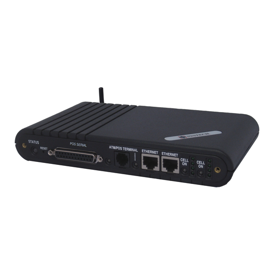
Chapter 2: Installing the Hardware This chapter describes installing the hardware, including: • Planning the installation • Checking cables and connectors • Sample configurations Overview Installing the IPG hardware includes the following steps: 1. Plan the installation 2. Connect your peripheral device(s) to the IPG device server Attach each peripheral device (e.g., POS terminal, cash register, card reader, modem) to a phone line port (RJ-11 connector on the front) or serial port (DB-25 connector). - Page 8 IPG Panel Connectors The following figures show the connectors and LED locations for the IPG models. There are: • zero, or one DB-25 female serial port • zero, or one RJ-11 telephone (terminal) port • one cellular antenna connector • one Ethernet port IPG Front Panel Connectors IPG Rear Panel Connectors...
-
Page 9: Connecting Devices To The Ipg
Connecting Devices to the IPG POS Terminal Port The POS Terminal port is a phone line designed to function just like a standard wall-jack analog phone line. It is designed primarily to connect POS (Point Of Sale) terminals, with an internal modem, to the IPG, which then routes data from the devices over the network. - Page 10 DB-25 RS-232 Number Name Direction Signal Function Serial data in, from remote device to IPG Serial data out, from IPG to remote device Flow control, to enable IPG to send data Flow control, to enable remote device to send data Signals remote device that the IPG is attached and powered on Signal ground...
-
Page 11: Cellular Interface
Figure 2-3 shows a minimal 3-wire cable using only RX (pin 2, data in), TX (pin 3, data out), and GND (pin 5, ground). DB-25 Pin (DTE) DB-25 Pin (DCE) Number/Signal Number/Signal 2 TX 2 TX 3 RX 3 RX 7 GND 7 GND Figure 2-3: DB-25 to DB-25 3-wire Cable... -
Page 12: Ethernet Lan
Ethernet LAN The IPG may also be connected to your LAN using an Ethernet port. The Cellular interface is typically the primary network connection but the local connection may also be used to configure or diagnose operation on the IPG. The Ethernet port on the IPG is a standard 10/100 Base-TX RJ-45 jack. -
Page 13: Starting The Ipg
Starting the IPG When the IPG is powered up, the LEDs indicate the status of the unit and its ports. The following LED colors and patterns will be displayed during normal startup, if no errors are detected. • Status LED – initially this LED will be yellow, but will quickly turn green. If the status LED is solid green, then the IPG doesn’t have a permanent IP address and is trying to obtain one from a DHCP server. -
Page 15: Chapter 3: Troubleshooting
Chapter 3: Troubleshooting The IPG has several LED indicators: Unit Status, Ports (serial, POS terminal or modem), Cellular and Ethernet. The LEDs use red, yellow, and green blinking combinations to indicate the status of each of the IPG’s major components. Status LED The status LED indicates the overall status of the IPG. -
Page 16: Cellular/Serial/Terminal/Modem Port Leds
Cellular/Serial/Terminal/Modem Port LEDs Each port has a Port LED that describes port activity. Table 3-2 describes the various Port LED states. Port LED Condition Meaning Port is closed or no power. Solid Green Port is open, but idle. Blinking Green Port is open, and data is being transmitted or received. -
Page 17: Appendix: Specifications
Appendix: Specifications IPG Hardware Specifications • ARM7 50MHz CPU • 1MB to 8Mbytes in-circuit boot flash and program memory • 8 to 32 Mbytes SDRAM • CDMA Cellular interface with SMA female antenna interface • 10/100 Mbps Ethernet connection over 10/100 Base-TX physical lines •... -
Page 18: Product Dimensions
Product Dimensions The IPG models measure: 8 inches x 4.75 inches x 1.25 inches (203 mm x 121 mm x 32 mm) Model Numbers Model Terminal Port Serial Port IPG/7701 IPG/7710 IPG/7711 Cellular specifications CDMA1xRTT 800/1900 MHz Ethernet cabling specifications This section describes guidelines for using 10/100 Base-TX twisted-pair cabling: •... - Page 19 Index 10/100 Base-TX, cabling specifications, 18 installation, hardware, 7 3-wire diagram IPG/7000, 10 connecting IPG to, 12 diagram, 8 overview, 15 start up, 13 800/1900 MHz, 18 MHz, 18 antenna, 7, 8, 17 asynch port specifications, 17 panel, diagram, 8 cable diagram terminal, DB-9 to DB-25, 10 red LED, 13...
Need help?
Do you have a question about the IPG-7700 Series and is the answer not in the manual?
Questions and answers