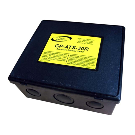
Summary of Contents for Go Power TS-30
- Page 1 Go Power! Manual GP TS-30 Go Power! Electric Inc. PO Box 6033 Victoria, BC V8P 5L4 Tel: 866-247-6527 Fax: 866-607-6527 Email: info@gpelectric.com...
-
Page 2: Table Of Contents
Go Power! TS-30 Owner’s Manual Table of Contents INTRODUCTION................ 3 INSTALLATION................. 3 OPERATIONAL TESTING............6 TROUBLESHOOTING............... 6 HI-POT TESTING ..............8 GENERATOR NOTE ..............8 MEDICAL APPLIANCES............8 CAUTION................... 9 WARRANTY ................9 Go Power! Electric Inc. PO Box 6033... -
Page 3: Introduction
The TS-30 can be installed at the electrical entry of the RV on the line side of the main distribution panel, or it can be installed on the load side of the panel between the main panel and a sub panel, allowing switching for either the entire electrical load or only designated circuits. - Page 4 3. Connect output to panel to terminals 3 and 4 (on the wide end of the relay). The TS-30 is designed with a time delay module to provide generators a brief warm- up period before supplying the load. The bypass switch on the time delay module should be in the “off”...
- Page 5 Go Power! TS-30 Owner’s Manual 2.5.2 INSTALLATION BETWEEN INVERTER AND ALTERNATING SOURCE (CONFIGURATION C) 1. For installation between inverter (default) and another power supply (dominant), such as the output from a prior power cord/ generator transfer switch. These connections will allow any other supply to dominate the inverter, and the inverter output will pass through the normally closed contacts of the switch.
-
Page 6: Operational Testing
2.5.3 INSTALLATION IN HYBRID SYSTEM FOR DESIGNATED CIRCUITS (CONFIGURATION D) The TS-30 A can be installed between inverter (default) and a circuit panel supplied by a larger amp alternating power supply (dominant). 1. Connect the inverter to terminals 7 and 8. - Page 7 Go Power! TS-30 Owner’s Manual you experience general low voltage conditions, remember that brownouts can be harmful to most appliances. A better alternative might be to utilize the generator until park voltage conditions improve. 4.3 LOCALIZED LOW VOLTAGE Low voltage conditions can be caused by specific situations such as an additional cord, which is too long and too small for the load.
-
Page 8: Hi-Pot Testing
7. MEDICAL APPLIANCES Go Power! Electric will not knowingly sell a Go Power! Automatic Transfer Switch for any life-support application. It is strongly recommended that you do not operate any life support equipment from a transfer switch. If the switch should malfunction,... -
Page 9: Caution
Go Power! Transfer Switches in the continental United States and Canada from defects in materials or workmanship under normal use for two years from date of retail purchase and will repair or replace any TS-30 free of charge. For complete warranty details, consult you local Go Power! Sales Representative.


Need help?
Do you have a question about the TS-30 and is the answer not in the manual?
Questions and answers