Garmin GTX327 Installation Manual
Transponder
Hide thumbs
Also See for GTX327:
- Installation manual (55 pages) ,
- Pilot's manual (8 pages) ,
- Pilot's manual (4 pages)

Related Manuals for Garmin GTX327


Summary of Contents for Garmin GTX327
- Page 1 TRANSPONDER INSTALLATION MANUAL Garmin International, Inc. 190-00187-02 Revision K January 2005...
- Page 2 Garmin. Garmin hereby grants permission to download a single copy of this manual and of any revision to this manual onto a hard drive or other electronic storage medium to be viewed and to...
- Page 3 California to cause cancer, birth defects, or reproductive harm. This Notice is being provided in accordance with California's Proposition 65. If you have any questions or would like additional information, please refer site www.garmin.com/prop65. GTX 327 Installation Manual Page i 190-00187-02 Preliminary Revision K...
- Page 4 This page intentionally left blank Page ii GTX 327 Installation Manual Revision K Preliminary 190-00187-02...
-
Page 5: Table Of Contents
TABLE OF CONTENTS PARAGRAPH PAGE GENERAL DESCRIPTION......................1-1 1.1 Introduction............................1-1 1.2 Equipment Description ........................1-1 1.3 Mutual Suppression Pulses ........................1-2 1.4 Interface Summary..........................1-2 1.5 Technical Specifications ........................1-3 1.6 Installation Approval .........................1-4 1.7 Aircraft Station License Requirements ....................1-5 1.8 Reference Documents ........................1-5 1.9 Limited Warranty..........................1-6 INSTALLATION OVERVIEW ......................2-1 2.1 Introduction............................2-1 2.2 Installation Material...........................2-1... -
Page 6: Paragraph Page
PARAGRAPH PAGE POST INSTALLATION CONFIGURATION & CHECKOUT PROCEDURE ......5-1 Operation ............................5-1 Configuration Pages ........................5-4 APPENDIX A CERTIFICATION DOCUMENTS A.1 Continued Airworthiness ........................A-1 A.2 Environmental Qualification Forms, GTX 327 Transponder ............A-1 APPENDIX B ASSEMBLY AND INSTALLATION DRAWINGS APPENDIX C INTERCONNECT DRAWINGS Page iv GTX 327 Installation Manual Revision K Preliminary... - Page 7 LIST OF ILLUSTRATIONS FIGURE PAGE 2-1 Antenna Installation Considerations ....................2-2 2-2 GTX 327 Unit Rack...........................2-7 4-1 Rear Connector, J3271........................4-1 4-2 Dual GTX 327, Single Encoder, Serial Input Connections ...............4-4 4-3 GTX 327 Software Update Connections ...................4-6 5-1 GTX 327 Front Panel.........................5-1 A-1 GTX 327 Environmental Qualification Form ..................
- Page 8 (see date on front cover) and is subject to change without notice. Authorized Garmin Sales and Service Centers are encouraged to access the most up-to-date bulletin and advisory information on the Garmin Dealer Resource web site at www.garmin.com using their Garmin -provided user name and...
-
Page 9: General Description
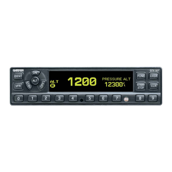
Equipment Description The Garmin GTX 327 is a panel-mounted transponder with the addition of altitude reporting and timing functions. The transponder is a radio transmitter and receiver that operates on radar frequencies, receiving ground radar or TCAS interrogations at 1030 MHz and transmitting a coded response of pulses to ground-based radar on a frequency of 1090 MHz. -
Page 10: Mutual Suppression Pulses
Mutual Suppression Pulses Other equipment on board the aircraft may transmit in the same frequency band as the transponder, such as DME or another transponder. Mutual suppression is a synchronous pulse that is sent to the other equipment to suppress transmission of a competing transmitter for the duration of the pulse train transmission. -
Page 11: Technical Specifications
Technical Specifications The following table presents general environmental specifications. For detailed specifications, see the Environmental Qualification form in Appendix A. 1.5.1 Electrical Specifications Characteristic Specification TSO, JTSO TSO C74c Class 1A, JTSO-C74c Class 1A TSO ENV CAT Refer to Appendix A FCC Authorization Emission Designator 11M0M1D Applicable Documents... -
Page 12: Installation Approval
1.5.2 Physical Characteristics Characteristic Specification Bezel Height 1.65 inches (42 mm) Bezel Width 6.25 inches (159 mm) Rack Height (Dimple to Dimple) 1.68 inches (43 mm) Rack Width 6.30 inches (160 mm) Depth Behind Panel with Connectors 8.77 inches (223 mm) (measured from face of aircraft panel to rear of connector backshells) GTX 327 Unit Weight... -
Page 13: Aircraft Station License Requirements
The UHF transmitter in this equipment is guaranteed to meet federal communications commission acceptance over the operating temperature range. Modifications not expressly approved by Garmin could invalidate the license and make it unlawful to operate the equipment. Reference Documents If the GTX 327 is installed with a GNS 480 (CNX80) unit, the following publication is a source of additional information. -
Page 14: Limited Warranty
Garmin retains the exclusive right to repair or replace the unit or software or offer a full refund of the purchase price at its sole discretion. SUCH REMEDY SHALL BE YOUR SOLE AND EXCLUSIVE REMEDY FOR ANY BREACH OF WARRANTY. -
Page 15: Installation Overview
Mounting Rack, Backplate and Connector Kit 010-10161-01 (Includes 115-00431-00, 011-00677-01 and 011-00651-01) Garmin GTX 327 Antenna kit* 010-10160-00 * Notes: Mounting Rack P/N 115-00431-00 replaces P/N115-00285-00. A transponder antenna approved to TSO C66( ) or C74( ) that has been installed to meet the requirements of this manual may be approved for use with the GTX 327. -
Page 16: Installation Considerations
• Encoding Altitude Digitizer - Use encoding altimeter manufacturer’s instructions, install according to FAA AC 43.13-1B and AC 43.13-2A. The Garmin GAE 43 (Garmin P/N 013-00066-00) can provide altitude data in either serial or parallel gray code format. Installation Considerations The GTX 327 can interface with equipment including altimeters and Air Data Computer (ADC). -
Page 17: Cabling And Wiring
A. The antenna (Garmin P/N 010-10160-00) should be mounted away from major protrusions, such as engine(s), propeller(s), and antenna masts. It should also be as far as practical from landing gear doors, access doors, or other openings that could effect its radiation pattern. - Page 18 Max. Length Insertion loss ECS Type MIL-C-17 Type RG Type (feet – [m]) (dB/100ft) 6' 1.3" [1.86m] 18.0 M17/128-RG400 RG-400 7' 7.3" [2.32m] 14.45 3C142B 9' 2.0" [2.79m] 12.00 M17/112-RG304 RG-304 12' 6.0" [3.81m] 8.80 311601 M17/127-RG393 RG-393 15' 5.4" [4.71m] 7.12 311501 19' 9.4"...
-
Page 19: Installation Approval Considerations For Pressurized Aircraft
Installation Approval Considerations for Pressurized Aircraft Antenna and cable installations on pressurized cabin aircraft require FAA approved installation design and engineering substantiation data whenever such installations incorporate alteration (penetration) of the cabin pressure vessel by connector holes and/or mounting arrangements. Use of existing bulkhead connectors previously approved by other means is permissible without additional approval. -
Page 20: Cooling Air
Cooling Air The GTX 327 meets all applicable TSO requirements without forced air cooling. The application of forced air cooling to the rear air nozzle of the GTX 327 is highly recommended to provide beneficial cooling to the unit. The GTX 327 was designed to handle a constant 450 PRF, with short periods of 1200 PRF. Rate limit is set at 1200 PRF. - Page 21 2.8.2 Mechanical Installation NOTE Avoid installing the unit near heat sources. If this is not possible, insure that additional cooling is provided. Allow adequate space for installation of cables and connectors. The installer will supply and fabricate all of the cables. All wiring must be in accordance with FAA AC 43.13-1B and AC 43.13-2A.
- Page 22 This page intentionally left blank Page 2-8 GTX 327 Installation Manual Revision K 190-00187-02...
-
Page 23: Installation Procedure
If the unit is damaged, notify the carrier and file a claim. To justify a claim, save the original shipping container and all packing materials. Do not return the unit to Garmin until the carrier has authorized the claim. -
Page 24: Circuit Breaker Placard
NOTES 1. Non-Garmin part numbers shown are not maintained by Garmin and consequently are subject to change without notice. 2. Extracting the #16, #18 and #20 contact requires that the expanded wire barrel be cut off from the contact. It may also be necessary to push the pin out from the face of the connector when using an extractor due to the absence of the wire. -
Page 25: System Interconnects
SYSTEM INTERCONNECTS Figure 4-1. Rear Connector, J3271 Table 4-1. P3271 Pin Assignments Pin Name AVIONICS MASTER ON RS-232 IN 2 ALTITUDE A1 ALTITUDE C2 ALTITUDE A2 ALTITUDE A4 ALTITUDE C4 EXTERNAL IDENT INPUT* ALTITUDE B1 ALTITUDE C1 ALTITUDE B2 ALTITUDE B4 POWER GROUND SWITCHED POWER OUTPUT POWER INPUT (+11 TO +33 VDC) -
Page 26: Power And Lighting Function
Power and Lighting Function Power Input requirements and Lighting Bus input are listed in the following tables. The power-input pins accept 11-33 Vdc. Switched Power Out is a power source available for devices such as a remote digital altitude encoder. Refer to Figures C-1 and C-2 for power interconnections. 4.1.1 Aircraft Power Table 4-2. -
Page 27: Altitude Functions
For altimeters that can be connected in both serial data and parallel gray code format, such as the Garmin GAE 43 (Garmin P/N 013-00066-00), select one or the other but not both wiring connections. - Page 28 4.2.2 Altimeter Interconnect, Dual GTX 327 Installation Refer to Figure 4-2 and Figure C-3, sheets 1 and 2 for Dual GTX 327 altimeter interconnections. A dual GTX 327 installation can accept either parallel wire gray code altimeter input or RS-232 serial data input as shown.
-
Page 29: Discrete Inputs
Discrete Inputs Table 4-5. Discrete Inputs Pin Assignments Pin Name Pin Number EXTERNAL IDENT SELECT* XPDR SYSTEM ID PROGRAM* AIRBORNE SENSE (SQUAT SWITCH) EXTERNAL SUPPRESSION (TXP/DME) In/Out These inputs are considered active if either the voltage to ground is < 1.9 V or the resistance to ground is <... -
Page 30: Rs-232 Input/Output, Software Update Connections
4.3.1 RS-232 Serial Data Electrical Characteristics The GTX 327 can be configured to include GPS, Altitude and Airdata data inputs on two RS-232 input lines. Altitude data supplied to the GTX 327 can be output to the GPS on an RS-232 output line. Table 4-6. -
Page 31: Post Installation Configuration & Checkout Procedure
POST INSTALLATION CONFIGURATION & CHECKOUT PROCEDURE Operation NOTE The coverage you can expect from the GTX 327 is limited to line of sight. Low altitude or aircraft antenna shielding by the aircraft itself may result in reduced range. Range can be improved by climbing to a higher altitude. It may be possible to minimize antenna shielding by locating the antenna where dead spots are only noticed during abnormal flight attitudes. - Page 32 NOTE Any time the function switch is in the ON or ALT position the transponder becomes an active part of the Air Traffic Control Radar Beacon System (ATCRBS). The transponder also responds to interrogations from TCAS equipped aircraft. • IDENT Pressing the IDENT key activates the Special Position Identification (SPI) Pulse for 18 seconds, identifying the transponder return from others on an air traffic controller’s screen.
-
Page 33: Function Display
5.1.2 Function Display PRESSURE ALT Displays the altitude data supplied to the GTX 327 in feet, hundreds of feet (i.e., flight level), or meters, depending on configuration. FLIGHT TIME Displays the Flight Time, controlled by the START/STOP key or by one of four airborne sources (squat switch, GPS ground speed recognition, airdata airspeed recognition or altitude increase) as configured during installation. -
Page 34: Configuration
Avoid selecting code 7500 and all codes in the 7600-7777 range. These codes trigger special indicators in automated facilities. An aircraft’s transponder code is used for ATC tracking purposes, therefore exercise care when making routine code changes. Configuration Pages With the unit turned off, holding down the FUNC key and pressing one of the power on keys provides access to the configuration pages. - Page 35 LVL (Level) Shows the current level of display backlighting, based on the lighting input source (lighting bus voltage, or the ambient light if the source is PHOTO) and the settings on this configuration page. This field has a range of 0 (zero) to 999. The level is set by pressing the 8 and 9 keys when MAN mode is selected. When in AUTO mode, the field is for display only.
- Page 36 KEY (Key Lighting) Selection Description Key lighting is controlled manually by the pilot on the GTX 327 MAN (Manual) DISPLAY page. Key lighting is automatically controlled based on the parameters AUTO (Automatic) entered on this configuration page. LVL (Level) Shows the current level of key lighting, based on the lighting input source (lighting bus voltage, or the ambient light if the source is PHOTO) and the settings on this configuration page.
- Page 37 5.2.4 CONTRAST CONFIGURATION Page CONTRAST MODE CONTRAST CONFIGURATION Page Selection Description MAN (Manual) The display contrast is manually adjusted either here or by the pilot using the GTX 327 CONTRAST page. AUTO (Automatic) DEFAULT. The display contrast is automatically compensated for temperature and other factors.
- Page 38 5.2.5 RS-232 INPUT/OUTPUT Page This is the electrical source for the GTX 327 altitude and RS-232 INPUT/OUTPUT Page GPS data input. Refer to paragraph 4.2.3 for altimeter data selection priority. RS-232 INPUT (Altitude Source, GPS Data) SELECTION DESCRIPTION DEFAULT. The altitude code input is not from an RS-232 source. RS-232 ground speed from a GPS device.
- Page 39 5.2.6 OPERATION CONFIGURATION Pages 5.2.6.1 First Configuration Page First Configuration Page VS RATE (Vertical Speed Rate) This field is the typical vertical speed for climb/descent of the aircraft. This number determines when a climb or descent arrow is displayed on the PRESSURE ALT page of the GTX 327. The range is 0 (zero) feet per minute to 9999 feet per minute.
- Page 40 5.2.6.2 Second Configuration Page SQUAT SWITCH Second Configuration Page The GTX 327 Flight Time may be based on the squat switch state. The squat switch field may be set to either YES or NO. (Default NO). If YES, sense may be set to HIGH or LOW. If set to NO, airborne status for auto standby and flight timer features will be determined by input data.
- Page 41 5.2.7 AIRCRAFT TYPE Page AIRCRAFT TYPE Page SELECTION DESCRIPTION UNKNOWN, <15.5K, >=15.5K, or ROTOR. AC TYPE AIRCRAFT TYPE Used for Automated Airborne Determination (time to STBY, required airspeed, ground speed). Sets the AIRCRAFT TYPE to ROTOR, to a weight of less than 15,500 pounds, more than or equal to 15,500 pounds, or unknown weight.
- Page 42 5.2.10 EXTERNAL SWITCH Page Displays the state of the external switch discrete inputs. EXTERNAL SWITCH Page IDENT Displays the state of the EXTERNAL IDENT discrete input. The box is filled when EXTERNAL IDENT is grounded. STANDBY Displays the state of the EXTERNAL STANDBY discrete input. The box is filled when EXTERNAL STANDBY is grounded.
-
Page 43: Appendix Acertification Documents
APPENDIX A CERTIFICATION DOCUMENTS Consistent with N8110.69 or Order 8110.4, Aviation Authority approved installers are hereby granted permission to use STC #SA00870WI data to modify aircraft. GTX 327 Installation Manual Page A-1 190-00187-02 Revision K... - Page 44 Page A-2 GTX 327 Installation Manual Revision K 190-00187-02...
-
Page 45: Continued Airworthiness
ICA. Following is a suggested ICA for a Garmin GTX 327 unit installation. Some of the checklist items do not apply, in which case they should be marked “N/A” (Not Applicable). - Page 46 Maintenance Instructions Maintenance of the GTX 327 is ‘on condition’ only. Periodic maintenance is not required. Refer to the GTX 327 Maintenance Manual. Troubleshooting Information Refer to the GTX 327 Maintenance Manual. Removal and Replacement Information Refer to Section 2 of this manual. If the unit is removed and reinstalled, a functional check of the equipment should be conducted in accordance with Section 5 of this manual.
- Page 47 337, dated ______) along with a statement that the ICA is now part of the aircraft’s inspection/maintenance requirements. Environmental Qualification Forms, GTX 327 Mode A/C Transponder The following pages are copies of the Environmental Qualification Forms for the Garmin GTX 327 Transponder (005-00089-51) provided for reference only. GTX 327 Installation Manual Page A-5...
- Page 48 Figure A-1. GTX 327 Environmental Qualification Form (Sheet 1 of 2) Page A-6 GTX 327 Installation Manual Revision K 190-00187-02...
- Page 49 Figure A-1. GTX 327 Environmental Qualification Form (Sheet 2 of 2) GTX 327 Installation Manual Page A-7 190-00187-02 Revision K...
- Page 50 This page intentionally left blank Page A-8 GTX 327 Installation Manual Revision K 190-00187-02...
Need help?
Do you have a question about the GTX327 and is the answer not in the manual?
Questions and answers
how to change the callsign in the. transponder