Table of Contents
Advertisement
Quick Links
Advertisement
Table of Contents

Related Manuals for Topcon HiPer Pro


Summary of Contents for Topcon HiPer Pro
- Page 1 ® Operator’s Manual PRECISION GPS+: HiPer Pro...
- Page 3 Rev B ©Copyright Topcon Positioning Systems, Inc. December, 2004 All contents in this manual are copyrighted by Topcon. All rights reserved. The information contained herein may not be used, accessed, copied, stored, displayed, sold, modified, published, or distributed, or otherwise reproduced without express written consent from Topcon.
- Page 4 ECO#2386...
-
Page 5: Table Of Contents
Table of Contents Preface ..............v Terms and Conditions ............v Regulatory Information ............viii Manual Conventions ............ix Chapter 1 Introduction ............1-1 Overview ................1-2 Principles of Operation ............1-2 GPS Overview ............... 1-2 Calculating Positions ..........1-3 GPS Positioning ............ - Page 6 Surveying with the Receiver ..........3-5 Static Survey ..............3-5 Kinematic (Stop and Go) Survey ........3-8 Real-time Kinematic Survey ......... 3-10 Set up an RTK Base Station ........3-10 Set up an RTK Rover ..........3-14 HiPer Pro Operator’s Manual...
- Page 7 Table of Contents Chapter 4 Operation ..............4-1 Using the MINTER .............. 4-2 Power Key ..............4-2 Status LED ..............4-2 Reset Key ..............4-3 FN Key and Record LED ..........4-3 Battery LED ..............4-7 Modem LED ..............4-8 Information Modes ............
- Page 8 USB Connector ............. A-12 Appendix B Safety Warnings ............B-1 General Warnings ..............B-1 Internal Battery Pack Warnings .......... B-2 Usage Warnings ..............B-3 Appendix C UHF Radio Usage ............ C-1 Appendix D Warranty Terms ............D-1 Index HiPer Pro Operator’s Manual...
-
Page 9: Preface
Preface Preface Thank you for purchasing this Topcon product. The materials available in this Manual (the “Manual”) have been prepared by Topcon Positioning Systems, Inc. (“TPS”) for owners of Topcon products, and is designed to assist owners with the use of the receiver and its use is subject to these terms and conditions (the “Terms and... - Page 10 TPS. Windows® is a registered trademark of Microsoft Corporation. The Bluetooth® word mark and logos are owned by Bluetooth SIG, Inc. and any use of such marks by Topcon Positioning Systems, Inc. used under license. Satel is a trademark of Satel, Oy. Product and company names mentioned herein may be trademarks of their respective owners.
- Page 11 Terms and Conditions exclusive, non-transferable license to use such Software under the terms stated herein and in any case only with a single receiver or single computer. You may not assign or transfer the Software or this license without the express written consent of TPS. This license is effective until terminated.
-
Page 12: Regulatory Information
• Reorient or relocate the receiving antenna. • Move the equipment away from the receiver. • Plug the equipment into an outlet on a circuit different from that to which the receiver is powered. HiPer Pro Operator’s Manual viii... -
Page 13: Manual Conventions
Manual Conventions • Consult the dealer or an experienced radio/television technician for additional suggestions. CAUTION CAUTION Any changes or modifications to the equipment not expressly approved by the party responsible for compliance could void your authority to operate such equipment. Canadian Emissions Labeling Requirements This Class B digital apparatus meets all requirements of the Canadian... - Page 14 WARNING WARNING Notification that an action will result in system damage, loss of data, loss of warranty, or personal injury. ANGER DANGER NDER NO CIRCUMSTANCES SHOULD THIS ACTION BE PERFORMED HiPer Pro Operator’s Manual...
-
Page 15: Chapter 1 Introduction
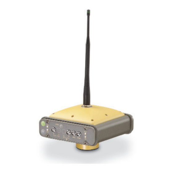
This chapter describes: • The HiPer® Pro receiver (Figure 1-1) • GPS and your receiver • Common receiver functions • Standard package contents and configurations • Receiver components • The Option Authorization File (OAF) Figure 1-1. HiPer Pro Receiver P/N 7010-0681... -
Page 16: Overview
The HiPer Pro can receive and process both L1 and L2 signals, improving the accuracy of your survey points and positions. The dual- frequency and GPS+ features of HiPer Pro combine to provide a real time kinematic (RTK) system accurate for short and long baselines. -
Page 17: Calculating Positions
Principles of Operation For information on the current status of the GPS constellation, visit http://tycho.usno.navy.mil/ or http://www.navcen.uscg.gov/. For GLONASS, visit http://www.glonass-center.ru/frame.html. Despite numerous technical differences in the implementation of these systems, both GPS and GLONASS have three essential components: • Space – GPS and GLONASS satellites orbiting approximately 12,000 nautical miles above Earth and are equipped with a clock and radio. -
Page 18: Gps Positioning
– Receiver Autonomous Integrity Monitoring (RAIM) detects faulty GPS and GLONASS satellites and removes them from the position calculation. – Five or more visible satellites for only GPS or only GLONASS; six or more satellites for mixed scenarios. HiPer Pro Operator’s Manual... -
Page 19: Conclusion
Principles of Operation – Wide Area Augmentation Systems (WAAS, EGNOS, etc.) creates and transmit, along with DGPS corrections, data integrity information (for example, satellite health warnings). – Current ephemerides and almanacs. Conclusion This overview simply outlines the basics of GPS and GLONASS positioning. -
Page 20: Standard Package Contents
• Setting different mask angles • Setting different survey parameters • Static or dynamic modes The range of the HiPer Pro is 2–4 miles (3.22–6.44 km). Standard Package Contents The HiPer Pro comes in a real-time kinematic (RTK) package with two receivers, one as a Base Station and the other as a Rover Station (also, refer to the packaging instruction card). -
Page 21: Cables
Standard Package Contents Cables Standard cables (Figure 1-2) can include the following: • Receiver-to-computer RS232 serial cable (p/n 14-008005-03) – connects the receiver’s serial port and an external device (hand- held controller or computer) • Receiver-to-SAE power cable (p/n 14-008016-03) – connects the receiver’s power port and the power supply’s SAE connector or the extension cable’s SAE connector •... -
Page 22: Power Supply/Charger
Standard receiver software includes: • PC-CDU – controller software that can run on a Windows®- based computer. • FLoader – Topcon’s firmware loader; available on the Topcon website. • BTCONF – Topcon’s Bluetooth® wireless technology module configuration program; available on the Topcon website. -
Page 23: Literature
Standard Package Contents Software and software information are also available on the Topcon website (www.topcongps.com/software/index.html or http:// www.topcongps.com/software/3rdparty.html). The following software will also be useful for operating, caring for and using your receiver, and may be required for some applications. -
Page 24: Getting Acquainted
Euro cards. One of those cards is the GPS receiver and the other is used for UHF communications. See Table 1-2 on page 1-13 for a description of the operating times for the HiPer Pro receiver as a Base or Rover. For receiver specifications, see Appendix A. Internal Components The following sections describe the internal components of the HiPer Pro receiver. -
Page 25: Radio Modem
(that is, location) to the Rover station modem. The HiPer Pro Base/Rover receivers are shipped with the most commonly used settings for the radio modem. The Rover settings are configured to match the Base settings. -
Page 26: Gps+ Receiver Board
• GPS L1 or GPS L1/L2 • GPS/GLONASS L1 or GPS/GLONASS L1/L2 Table 1-1 lists the options available for these cards. Table 1-1. Euro Card Options for HiPer Pro Euro Card Model Available Options Euro-112T (HGGDT) G: GPS L1... -
Page 27: External Components
Standby mode 13 hours 16 hours The Li-Ion batteries used in the HiPer Pro should run at no less than 98% capacity after 500 charging cycles. These batteries do not need to be drained before recharging. A battery charger (AC adapter) is included with the standard package. -
Page 28: Front Panel
Introduction Figure 1-4. HiPer Pro Radome Front Panel Figure 1-5 on page 1-15 shows front panel components for the HiPer Pro receiver: • MINTER – The Minimum INTERface for the receiver consisting of three keys and four, three-color LEDs. See “Using the MINTER”... - Page 29 • PWR – The power input port to which an external power source (+6 to +28 V DC) is connected and where the unit is charged. • Slant height measure mark (SHMM). MINTER Reset Power Slant Height Measure Mark Figure 1-5. HiPer Pro Front Panel P/N 7010-0681 1-15...
-
Page 30: Back Panel
Introduction Back Panel Figure 1-6 shows back panel components for the HiPer Pro. • Vent plug – Equalizes the pressure between the inside of the receiver and the outside environment. • Slant height measure mark (SHMM) Vent Plug Slant Height Measure Mark Figure 1-6. - Page 31 Option Authorization File (OAF) • Type of signal (standard L1; optional L2) • Memory (standard 0MB; optional 1MB up to 1GB) • Update rate standard 1Hz (optional 5, 10, or 20Hz) • RTK at 1Hz, 5Hz, 10Hz, and 20Hz • RTCM/CMR Input/Output •...
- Page 32 Introduction Notes: HiPer Pro Operator’s Manual 1-18...
-
Page 33: Chapter 2 Configuration
• Radio configuration • Bluetooth module configuration • Collecting almanacs Before you can begin using the HiPer Pro receiver, do the following: 1. Charge the batteries. See “Powering the Receiver” on page 2-2. 2. Configure the various parts of your receiver. See: •... -
Page 34: Powering The Receiver
The internal batteries can not be overcharged. The speed of the charge depends on the Power and Charger settings on the Receiver Configuration screen, and whether the receiver is HiPer Pro Operator’s Manual... -
Page 35: External Batteries
Powering the Receiver turned off or on. See “Power Management” on page 2-5 for more information. The Li-Ion batteries used in the receiver should run at no less than 98% capacity after 500 charging cycles. These batteries do not need to be drained before recharging. -
Page 36: Battery Charger
AC between 90 and 264 V 1A (110 V AC) and between 47 Hz and 63 Hz. The battery charger outputs DC 12 V 2.5 A (30 W). HiPer Pro Operator’s Manual... -
Page 37: Turning On/Off The Receiver
REC LEDs are off). This delay (about 1 second) will prevent the receiver from being turned off by mistake. Power Management You can use Topcon’s PC-CDU software to manage your receiver’s power. The complete description of PC-CDU exceeds the scope of this manual, but can be found in the PC-CDU User’s Manual. - Page 38 • Off – receiver will not charge batteries • Charge A – receiver charges only battery A • Charge B – receiver charges only battery B • Auto – receiver automatically detects and charges both batteries Figure 2-3. Select Charger Mode HiPer Pro Operator’s Manual...
- Page 39 Powering the Receiver 5. Select the Power output modes Ports drop-down list to set power output on the serial ports (Figure 2-4). • On – the power board will deliver voltage on pin one of all serial port connectors when the receiver is turned on. If the receiver is turned off, there will be no power on any ports.
- Page 40 (Figure 2-6). 9. Select and check the Enable Low Power Mode check box to put the receiver’s processor into low power consumption mode (Figure 2-6). Figure 2-6. Enable and Apply Power Settings 10. Click Apply. HiPer Pro Operator’s Manual...
-
Page 41: Charging Internal Batteries
Powering the Receiver Charging Internal Batteries Use one of the following conditions for maximum battery charge speed: • The receiver is turned off. Power Mode and Charger Mode are set to Auto. See “Power Management” on page 2-5 for setting these parameters. -
Page 42: Checking Internal Battery Status
USB cable), you will be able to: • configure the receiver and its components • send commands to the receiver • download files from the receiver’s memory • load new firmware using FLoader™, OAFs, and configuration files to a receiver HiPer Pro Operator’s Manual 2-10... -
Page 43: Establishing A Wireless Connection
Connecting the Receiver and a Computer Establishing a Wireless Connection The HiPer Pro receiver contains Bluetooth wireless technology that allows file transfer and synchronization between the receiver and any other external device that supports Bluetooth wireless technology; for example, an iPAQ, or a computer with USB-to-Bluetooth adapter or PCMCA-to-Bluetooth adapter installed. -
Page 44: Establishing An Rs232 Cable Connection
1. Using the USB cable, connect the USB port of your computer to the receiver’s USB port. 2. Press the power buttons on the receiver and computer to turn them on. 3. Continue with Step 1 in “Establishing a PC-CDU Connection” on page 2-13. HiPer Pro Operator’s Manual 2-12... -
Page 45: Establishing A Pc-Cdu Connection
Connecting the Receiver and a Computer Establishing a PC-CDU Connection PC-CDU is a Personal Computer-Control Display Unit software used to manage the various functions of your receiver. The full range of PC-CDU configuration and function is outside the scope of this manual. - Page 46 – Set the Connection mode (Direct). – Set the port for your computer (USB) from the Port drop- down list. – Select the receiver’s ID from the Rec ID drop-down list. Figure 2-9. USB Connection Parameters HiPer Pro Operator’s Manual 2-14...
-
Page 47: Receiver Configuration
Receiver Configuration Once a PC-CDU connection with the receiver has been established, the current communications settings—such as, port name, baud rate (if applicable), and flow control (if applicable) —display in the lower- left corner of the main window of PC-CDU. A timer begins to count up in the lower-right corner as well (Figure 2-10). - Page 48 If your jobsite is in an area that has obstructions (buildings, trees, etc.), and/or the antenna location is near reflective objects, configure the receiver to reduce errors from these sources. WARNING WARNING Do not make other changes without consulting the PC-CDU User’s Manual. HiPer Pro Operator’s Manual 2-16...
- Page 49 Receiver Configuration 4. Click the Advanced tab then the Multipath Reduction tab, enable the following boxes, and click Apply (Figure 2-12). • Code multipath reduction • Carrier multipath reduction Figure 2-12. Receiver Configuration – Advanced Tab 5. Click the Loop Management tab, enable the following boxes, and click Apply (Figure 2-13).
- Page 50 Disconnecting the receiver from the computer before exiting will eliminate any possible conflict in the management of your serial ports. Once the receiver is configured, the configuration will remain until you change it either using PC-CDU or clearing the NVRAM. HiPer Pro Operator’s Manual 2-18...
-
Page 51: Minter Configuration
MINTER Configuration MINTER Configuration The Minimum INTERface (MINTER) consists of three keys (Power, FN, and Reset) and four LEDs (STAT, REC, BATT, and RX) that control and display the receiver’s operation (Figure 2-15). Reset Power Button BATT (battery LED) STAT (status LED) REC (recording LED) (modem status LED) FN (function/recording button) - Page 52 • Always append to the file on page 2-22 • Files Creation mode on page 2-22 • Automatic File Rotation Mode (AFRM) on page 2-22 • FN key mode on page 2-23 • Initial data collection dynamic mode on page 2-24 HiPer Pro Operator’s Manual 2-20...
- Page 53 MINTER Configuration • Data recording auto-start on page 2-24 Figure 2-17. Receiver Configuration – MINTER Tab Recording Interval parameter This parameter specifies the message output interval into the log file when the MINTER FN key (pressed for 1–5 seconds) activates data logging. This setting is used for both logging a single log file, and logging receiver data in AFRM mode.
- Page 54 Values are 60 to 86400 seconds; default value is 3600 seconds. • Phase – specifies the “phase” (constant time shift) of creating multiple log files in AFRM mode. Values are 0 to 86400 seconds; default value is zero seconds. HiPer Pro Operator’s Manual 2-22...
- Page 55 MINTER Configuration • Files (total) – a counter that specifies how many multiple log files must be created in AFRM until this mode automatically turns off. This counter decrements on every file rotation until it value becomes zero, then file rotation automatically stops. The counter initializes with AFRM.
- Page 56 Receiver data not resume when open when power open when power is logged to power is restored. is restored and restored and data default file. data will log to will log to this file. this file. HiPer Pro Operator’s Manual 2-24...
- Page 57 MINTER Configuration Table 2-2. Data Recording Parameter Behavior (Continued) Enabled Radio Button Results Before Power Failure Always No file will open No file will open A log file with this File specified; with this name. with this name. name will open and receiver data Data logging will Data logging will...
-
Page 58: Radio Configuration
• Displaying information about the radio modem installed in the receiver. • Programming the radio modem’s settings. For HiPer Pro receivers, the integrated Satel radio modem provides TX/RX UHF communications between a Base Station and Rover. To configure the Satel radio modems, have the following ready: •... - Page 59 Radio Link and FCS settings to work properly together. 1. To connect to Modem-TPS, use an RS232 cable or Bluetooth wireless technology to connect the computer and HiPer Pro. 2. Turn on the receiver. 3. Open Modem-TPS and select the COM port the receiver is connected to (Figure 2-19).
-
Page 60: Setting The Radio Link
Base at 1000. Rover at 10. Rover at 10. Signal Threshold Power Base and Rover at -112. Base and Rover at -112. Free Channel Scan Base and Rover on same Base and Rover on same setting. setting. HiPer Pro Operator’s Manual 2-28... - Page 61 Radio Configuration Base Rover Figure 2-20. Radio Link Settings – Optimal Distance for Base and Rover The current frequency setting establishes the frequency used for communication between the Base Station and Rover. Available frequencies will vary by location. 1. To change the receiver’s frequency, set the Free Channel Scan field to OFF.
-
Page 62: Configuring Radio Channels
2. For peak performance, leave the default setting for the Channel Hop Threshold (the default is -105). 3. For both the Base Station and Rover, set the same Free Scan net ID. The Net ID uses a hexadecimal format from 0 to FF. HiPer Pro Operator’s Manual 2-30... - Page 63 Radio Configuration Occasionally, the receivers may encounter interference if a jobsite has more than one set of HiPer Pro receivers. In this case, enter a different Free Scan net ID for each set of receivers. Figure 2-22. FCS Tab 4. To set up the frequency list for communication between the Base Station and Rover, select a frequency from the Frequency list and click Add.
-
Page 64: Bluetooth Module Configuration
Once you have BTCONF available, follow these steps to configure the Bluetooth module. 1. Using the RS232 cable, connect the serial port of your computer (usually COM1) to the receiver’s serial port A. If needed, turn on the receiver and computer. HiPer Pro Operator’s Manual 2-32... - Page 65 Bluetooth Module Configuration 2. Run the Bluetooth module configuration program (Btconf.exe) (Figure 2-23). Figure 2-23. Bluetooth Module Configuration Main Screen Notice that the lower left corner shows a “Disconnected” status for the computer and Bluetooth module. For BTCONF version and copyright information, click the About button.
- Page 66 5. Click the Parameters tab (Figure 2-26 on page 2-35). The Parameters tab sets identifying and security information for your Bluetooth module. The security section allows you to set data security and unauthorized access parameters for the Bluetooth module. HiPer Pro Operator’s Manual 2-34...
- Page 67 Bluetooth Module Configuration 6. Enter up to 14 characters to set a unique name for the Bluetooth module (Figure 2-26), and click Apply. Figure 2-26. BTCONF Parameters Tab 7. To set security parameters (Figure 2-27 on page 2-36), enter and enable the following, then click Apply: •...
- Page 68 Figure 2-27. BTCONF Security Parameters 8. Click the Serial Interface tab (Figure 2-28). Enable Echo to display Bluetooth module replies and corresponding commands on the computer terminal. If needed, click Apply. Figure 2-28. BTCONF Serial Interface Tab HiPer Pro Operator’s Manual 2-36...
-
Page 69: Collecting Almanacs
Collecting Almanacs 9. Click Disconnect then Exit (Figure 2-29) to quit BTCONF. Figure 2-29. Click Disconnect then Exit Collecting Almanacs Each satellite broadcasts a message (almanac) which gives the approximate orbit for itself and all other satellites. If the receiver has an almanac, you can considerably reduce the time needed to search for and lock on to satellite signals. - Page 70 • If the last known receiver position, stored in the NVRAM, is different from the present position by several hundred kilometers. • After loading a new OAF. • After loading new firmware. • After clearing the NVRAM. • Before surveying. HiPer Pro Operator’s Manual 2-38...
-
Page 71: Setup And Survey
• RTK Base station setup • RTK Rover setup • Basic surveying with the HiPer Pro receiver The HiPer Pro package use one receiver as the Base station and the other as the Rover station. Receiver Setup To set up the receivers, you must: 1. -
Page 72: Step 1: Set Up The Receiver
1. Measure the antenna height above the point or marker. Figure 3-1 illustrates the antenna offsets. (See Figure 1-5 on page 1-15 and Figure 1-6 on page 1-16 for the exact SHMM location.) HiPer Pro Operator’s Manual... - Page 73 Receiver Setup SHMM 30.50mm 77.75mm Figure 3-1. HiPer Pro Antenna Offsets • SHMM to ARP vertical offset = 30.50mm • SHMM to ARP horizontal offset = 77.75mm Table 3-1gives the offset values for the receivers. Table 3-1. Antenna Offset Values for Receiver Options...
-
Page 74: Step 3: Collect Data
Manual. 3. When finished, press and hold the FN key until the REC LED light goes out. 4. To turn off the receiver, press and hold the power key until all lights go out, then release. HiPer Pro Operator’s Manual... -
Page 75: Surveying With The Receiver
Surveying with the Receiver Surveying with the Receiver Your receiver can be used to perform the following types of surveying: • Static • Kinematic • Real-time kinematic (RTK) Static Survey Static surveying is the classic survey method, well suited for all kinds of baselines (short, medium, long). - Page 76 After the survey completes, data the receivers collect can be downloaded onto a computer and processed using post-processing software (for example, Topcon Tools). The procedure that follows describes the steps the operator should take to perform a Static Survey using MINTER.
- Page 77 Surveying with the Receiver 3. Click the Advanced tab and then the Multipath tab, set the following parameters, then click Apply (Figure 3-3): • Code multipath reduction – enable • Carrier multipath reduction – enable Figure 3-3. Configure Multipath 4. Click the Loop Management tab and set the following parameters, then click Apply (Figure 3-4): •...
-
Page 78: Kinematic (Stop And Go) Survey
• FN key mode, Occupation mode switch – enable • Initial data collection dynamic mode, Kinematic – enable See Table 4-1 on page 4-5 for FN key functions and REC LED statuses. Figure 3-5. Rover MINTER Configuration HiPer Pro Operator’s Manual... - Page 79 Surveying with the Receiver NOTICE NOTICE Remember, both Base and Rover receivers must collect data from the same satellites, at the same data recording rate, and with identical elevation mask angles. 3. Set up the Rover at an unknown point and press power. Allow the Rover to collect static data for two to ten minutes.
-
Page 80: Real-Time Kinematic Survey
(Figure 3-6). Figure 3-6. Set All Parameters to Defaults 7. On the Receiver Configuration screen, click the MINTER tab and specify the desired settings. Refer to the PC-CDU User’s Manual for more information. HiPer Pro Operator’s Manual 3-10... - Page 81 Surveying with the Receiver 8. Click the Positioning tab and set the Elevation mask parameter to 15 (Figure 3-7), then click Apply. Figure 3-7. Configure Receiver Positioning – Elevation Mask 9. Select the Base tab, set the following parameters (Figure 3-8 on page 3-12), and click Apply: •...
- Page 82 • Baud rate drop-down list – select a baud rate (i.e., the rate at which differential messages will be transmitted from receiver to modem). • RTS/CTS – select to enable handshaking. Use a 38400 baud rate. HiPer Pro Operator’s Manual 3-12...
- Page 83 Surveying with the Receiver Figure 3-9. Base Configuration – Ports 11. Click Apply. The receiver begins sending data to the selected port. For more details on the settings available for configuring the Base station, refer to the PC-CDU User’s Manual. P/N 7010-0681 3-13...
-
Page 84: Set Up An Rtk Rover
2. Connect the receiver and computer. See “Connecting the Receiver and a Computer” on page 2-10. 3. Click Configuration Receiver. 4. Click the Positioning tab and set the Position Masks, Elevation mask (degrees) parameter to 15 (Figure 3-7 on page 3-11). HiPer Pro Operator’s Manual 3-14... - Page 85 Surveying with the Receiver 5. Click the Rover tab and set the desired Positioning Mode (Figure 3-11). Figure 3-11. Rover Configuration Adjust the following RTK Parameters settings: • Under RTK mode in the RTK Parameters section, choose either Extrapolation for RTK float (kinematic) or Delay for RTK fixed (static).
- Page 86 • RTS/CTS – select to enable handshaking. Use a 38400 baud rate. Figure 3-12. Rover Configuration – Ports 7. Click Apply. 8. Click OK to close the Receiver Configuration screen. HiPer Pro Operator’s Manual 3-16...
- Page 87 Surveying with the Receiver 9. On the main screen (Figure 3-13), check the LQ field to ensure the receiver obtains differential corrections. Usually, the receiver will start to output the coordinates of the antenna’s phase center along with the solution type within 10–30 seconds. However, spread spectrum radios may take as long as 60 seconds to synchronize.
- Page 88 If the receiver is not (for some reason) receiving differential corrections, or if none of the ports has been configured to receive differential corrections, the LQ field will either be empty or it will look like this: 100%(999,0000,0000). HiPer Pro Operator’s Manual 3-18...
-
Page 89: Chapter 4 Operation
• Checking and loading OAFs • Managing receiver memory • Clearing the NVRAM • Changing receiver modes • Checking and loading firmware Topcon receivers are built to operate independent of the receiver type. Any minor exceptions for the HiPer Pro are noted. P/N 7010-0681... -
Page 90: Using The Minter
Operation Using the MINTER The MINTER (Figure 4-1) is Topcon’s Minimum INTERface used to display and control data input and output, and is the same for all HiPer family receivers. Reset Power Button BATT (battery LED) STAT (status LED) REC (recording LED) -
Page 91: Reset Key
Using the MINTER Reset Key Pressing and holding the reset key for about one second causes: • a hard reset of the receiver. • the receiver to leave Zero Power Mode and return to Normal Mode. NOTICE NOTICE Only use this procedure if the receiver does not respond to commands or does not charge the internal batteries (is in Zero Power Mode). - Page 92 CDU (control display unit) applications or for data recording. This operation may require from fractions of a second to several minutes, depending on the circumstances and the amount of internal memory. HiPer Pro Operator’s Manual...
- Page 93 Using the MINTER Table 4-1. FN Key Functions and REC LED Status FN Key REC LED Status When data recording is off, and the FN key is... No light No data recording. Orange blink Internal file system test in progress. Not pressed No free memory;...
- Page 94 No light Release to stop data recording. seconds Pressed for 5–8 Release to turn serial port A baud rate to seconds 9600 bps. Pressed for > 8 No light No function (data recording still on). seconds HiPer Pro Operator’s Manual...
-
Page 95: Battery Led
• Blinking once a second – the batteries are being charged. • Blinking once every five seconds – the HiPer Pro uses the internal batteries for power. • Not blinking – the receiver is in Zero Power Mode or the internal batteries are completely discharged and no external power is connected. -
Page 96: Modem Led
In this mode, the receiver continues to work as usual, but the STAT LED indicates “extended” information using a The Delimiter is a distinguishable double-blink that shows the overall status of tests performed in EIM. The LED color for delimiter is HiPer Pro Operator’s Manual... - Page 97 Using the MINTER calculated from the colors of other LED blinks, and will be one of the following colors when the tests complete: • Orange – at least one blink is orange. • Red – no orange blink and at least one red blink. •...
-
Page 98: Downloading Files To A Computer
1. Connect your receiver and computer. See “Connecting the Receiver and a Computer” on page 2-10 for this procedure. 2. On the Connection Parameters dialog box, enable RTS/CTS handshaking (Figure 4-2). Figure 4-2. Connection Parameters – RTS/CTS Handshaking HiPer Pro Operator’s Manual 4-10... - Page 99 Downloading Files to a Computer 3. Click File File Manager, then click the Download path tab on the File Manager dialog box (Figure 4-3). Figure 4-3. Find Files to Download 4. Navigate to or create (using the Create button) the folder in which to download and store files.
- Page 100 Figure 4-5. Download Files – Status Indicators 7. Click Exit on the File Manager dialog box. 8. Continue with other operations. Or, click File Disconnect, then File Exit to quit PC-CDU (Figure 4-6). Figure 4-6. Click Disconnect then Exit HiPer Pro Operator’s Manual 4-12...
-
Page 101: Deleting Files
Deleting Files Deleting Files Use the following steps to delete files from your receiver. 1. Connect your receiver and computer. See “Connecting the Receiver and a Computer” on page 2-10 for this procedure. 2. On the Connection Parameters dialog box, enable RTS/CTS handshaking (Figure 4-7). -
Page 102: Checking Receiver Options
• Option name – a name/description of the option • Current – the current status of the option • Purchased – if the option is purchased or not • Leased – if the option is leased or not HiPer Pro Operator’s Manual 4-14... - Page 103 Checking Receiver Options • Expiration date – the date the option will be disabled, if applicable Since Options can be both purchased and leased, the “Current” status of the option displays the currently effective value. Option values can be: • -1 or “-----” – the firmware version does not support this option.
-
Page 104: Loading Oafs
Operation Loading OAFs Topcon Positioning System dealers provide customers with OAF files. For any OAF related questions, E-mail TPS at options@topconps.com. Please have your receiver ID number available (see “Checking Firmware Version” on page 4-21). 1. To load a new OAF, follow steps one and two in “Checking Receiver Options”... -
Page 105: Managing Receiver Memory
After clearing the NVRAM, your receiver will require some time to collect new ephemerides and almanacs (around 15 minutes). Clearing the NVRAM of your receiver will not delete any files already recorded in your HiPer Pro’s memory. However, it will reset your receiver to factory default values. P/N 7010-0681... -
Page 106: Using Minter To Clear Nvram
Receiver and a Computer” on page 2-10 for this procedure. 2. Click Tools Clear NVRAM (Figure 4-12). The REC LED flashes green and red; the STAT LED flashes red. Figure 4-12. Clear NVRAM with PC-CDU The receiver automatically disconnects when finished. HiPer Pro Operator’s Manual 4-18... -
Page 107: Changing Receiver Modes
Put the receive in Zero Power Mode to prevent this (see “Zero Power Mode” on page 4-20). Follow these steps to put the HiPer Pro into sleep mode. -
Page 108: Zero Power Mode
4. Press the Reset key for about one second to return to Normal mode. NOTICE NOTICE When the internal batteries have completely discharged and no external power is connected, the receiver will go into Zero Power Mode automatically to prevent the batteries from over discharging. HiPer Pro Operator’s Manual 4-20... -
Page 109: Checking Firmware Version
Checking Firmware Version Checking Firmware Version Use PC-CDU to check the firmware version of the receiver. 1. Connect the receiver and a computer. See “Connecting the Receiver and a Computer” on page 2-10 for this procedure. Click Help About. The About PC-CDU dialog box opens (Figure 4-13). Figure 4-13. -
Page 110: Loading New Firmware
Use the latest firmware version, available for download from the TPS website, to ensure your receiver has the most recent updates. NOTICE NOTICE The HiPer Pro receiver should be loaded with firmware version 2.4 or newer. CAUTION CAUTION Do not use firmware versions 2.3p2 or older. -
Page 111: Receiver And Power Board Firmware
Loading New Firmware Figure 4-14. FLoader Main Screen See the following sections to load the appropriate firmware. Receiver and Power Board Firmware Receiver and power board firmware is released as a compressed file that you download and decompress. This file contains the following three files: •... - Page 112 Capture (recommended) (Figure 4-16). Figure 4-16. Program Tab Settings 3. Browse for and select the receiver board’s RAM file and Flash file (Figure 4-16). 4. Click Load and wait until 100% of the files load into the receiver. HiPer Pro Operator’s Manual 4-24...
- Page 113 Loading New Firmware NOTICE NOTICE If you selected an incorrect file, an error message displays at the bottom of the dialog box. Select the correct file. 5. Select the Device tab and set the Device Type as Receiver’s Power Board. Then click Get from Device for device information (Figure 4-17).
- Page 114 Select the correct file. 9. Click File Exit. 10. Clear the receiver’s NVRAM (see “Clearing the NVRAM” on page 4-17) and update the almanac (see “Collecting Almanacs” on page 2-37) after loading new firmware. HiPer Pro Operator’s Manual 4-26...
-
Page 115: Bluetooth Module Firmware
Loading New Firmware Bluetooth Module Firmware Bluetooth module firmware is released as a compressed file that you download and decompress. This file contains the following two files: • btloader.ldr – the Bluetooth module RAM file • btmain.ldp – the Bluetooth module Flash file NOTICE NOTICE You must load both files when loading new firmware. - Page 116 Figure 4-21. Bluetooth Firmware Load Complete NOTICE NOTICE If you selected an incorrect RAM or Flash file, an error message displays at the bottom of the dialog box. Reselect the correct file. 5. Click File Exit. HiPer Pro Operator’s Manual 4-28...
-
Page 117: Chapter 5 Troubleshooting
Chapter 5 Troubleshooting In general, as long as you follow the maintenance and safety instructions provided in this manual, you should have few problems with your receiver. This chapter will help you diagnose and solve some common problems you may encounter with your receiver. WARNING WARNING Do not attempt to repair equipment yourself. -
Page 118: Power Problems
“Powering the Receiver” on page 2-2. but internal batteries are discharged. The receiver may have If after charging your internal batteries a defective charger or overnight, and your receiver is not defective internal powering, contact TPS Customer Support batteries. for advice. HiPer Pro Operator’s Manual... -
Page 119: Receiver Problems
Receiver Problems Receiver Problems The following are some of the most commonly encountered receiver problems. Problem The receiver cannot establish a connection to a computer or external controller. Causes Solutions The cable is not • Check that the cable connector is properly plugged in. - Page 120 See “Surveying with the Receiver” on page 3-5 for further information. • If the receiver should function as a Rover, ensure it has the proper configuration. See “Surveying with the Receiver” on page 3-5 for further information. HiPer Pro Operator’s Manual...
- Page 121 Receiver Problems The corresponding • See “Checking Receiver Options” on receiver options may page 4-14 for details on how to check be disabled or expired. current options. • Enable or prolong the validity of the corresponding receiver options by ordering a new OAF with the desired options activated.
- Page 122 See “External Batteries” on page 2-3. • See “Powering the Receiver” on page 2-2. The distance between • Close the distance between the Base and Base and Rover is too Rover. far. • Use repeaters to increase radio coverage. HiPer Pro Operator’s Manual...
-
Page 123: Bluetooth Problems
Bluetooth Problems Problem The receiver does not start data logging. Causes Solutions The receiver has no • Download receiver files to a computer (if free space for files. needed) and delete files (see “Downloading Files to a Computer” on page 4-10 and “Deleting Files” on page 4-13). - Page 124 • See “Checking Receiver Options” on receiver options may page 4-14 for details on checking current be disabled or expired. options. • Enable, or prolong, the corresponding receiver options. Contact your dealer to order an OAF with desired receiver options. HiPer Pro Operator’s Manual...
- Page 125 Bluetooth Problems Error Message Can’t find Bluetooth. Causes Solution The receiver’s Slot 3 is 1. Connect your receiver and a computer turned off. using an RS232 cable (see “Establishing an RS232 Cable Connection” on page 2-12). 2. Click Configuration Receiver General.
- Page 126 • Make sure your Bluetooth enabled settings probably devices use the same security settings. differ. • See “Bluetooth Module Configuration” on page 2-32, specifically Figure 2-27 on Figure 2-27 for details on changing security settings. HiPer Pro Operator’s Manual 5-10...
-
Page 127: Radio Modem Problems
Radio Modem Problems Bluetooth module 1. If you changed settings for your settings may have Bluetooth module, remove it from the changed. list of discovered Bluetooth devices using the Bluetooth manager program (supplied with the device used to manage the receiver). 2. -
Page 128: Obtaining Technical Support
For Questions Related To... Use... Hardware (receivers, antennas, firmware) hardware@topcon.com GPS+ and 3DMC psg@topcon.com options@topcon.com rtk@topcon.com PC-CDU pccdu@topcon.com If in doubt about which e-mail address to use for your particular question, please send it to support@topcon.com. HiPer Pro Operator’s Manual 5-12... -
Page 129: Website
Obtaining Technical Support Website The Topcon Positioning Systems website provides current information about Topcon’s line of products. The support area of the website provides access to frequently asked questions, configuration procedures, manuals, e-mail support, etc. To access the TPS website home page, use: www.topconpositioning.com... - Page 130 Troubleshooting Notes: HiPer Pro Operator’s Manual 5-14...
-
Page 131: Appendix A Specifications
Appendix A Specifications This TPS product is a 20-channel GPS receiver with an internal Satel® radio modem, a Bluetooth® wireless technology module, and a rugged aluminum housing complete with MINTER and cable connectors. NOTICE NOTICE Performance specifications assume a minimum of 6 GPS satellites above 15 degrees in elevation and adherence to the procedures recommended in this manual. -
Page 132: Receiver Specifications
Reset – receiver hardware reset LEDs Four LEDs: STAT – satellite and receiver status REC – record and data status BATT – battery status RX – modem status Environment Operating -30 C° to + 60 C° with batteries temperature HiPer Pro Operator’s Manual... - Page 133 Receiver Specifications Table A-1. Receiver Specifications (Continued) Storage temperature -40 C° to +75 C° with batteries Humidity Power Internal battery Li-ion, 4000 mAh, 7.4 V Not removable Battery size 132 x 35 x 18 (mm) Battery weight 165 g (1 battery) Number of built-in 2 batteries batteries...
- Page 134 1, 3, 9, 31, 32, 34; user selectable type Process interval 1Hz standard; 5, 10, 20Hz optional Output interval for 1Hz standard; 5, 10, 20Hz optional RTCM correction data Elevation mask 0 to 90 deg (independent of data logging HiPer Pro Operator’s Manual...
- Page 135 Receiver Specifications Table A-1. Receiver Specifications (Continued) Multi-base DGPS Differential correction select mode: Nearest, Mix, Best (optional) Correction format CMR2/CMR+ (Trimble compatible), RTCM SC104 Ver 2.2, 2.3, or 3.0 RTCM message 3, 18, 19, 20, 21, 22; user selectable type Ambiguity initialize OTF (L1, L1/L2) Baseline Length...
-
Page 136: Gps Board Details
20 channels (G, GG, GD, GGD) L1 GPS, L1/L2 GPS, L1 GLONASS, L1 GPS + L1 GLONASS, WAAS/EGNOS, PCode and Carrier Optional Cinderella days (see page A-7 for details) Tracked Signals GPS/GLONASS, L1/L2 C/A and P-Code and Carrier, WAAS/EGNOS HiPer Pro Operator’s Manual... - Page 137 Cinderella days is an option that turns a single frequency, GPS receiver into a dual-frequency, GPS+GLONASS receiver for 24 hours every other Tuesday at GPS midnight. Refer to Topcon’s website for more information and specific Cinderella day dates. P/N 7010-0681...
-
Page 138: Bluetooth Module Details
Number of channels Four to Six Frequency stability <± 1.5 kHz Type of emission Communication Half-duplex mode Data speed of serial 300–38400 bps interface Data speed of radio 19200 bps (25kHz channel) interface 9600 bps (12.5 kHz channel) HiPer Pro Operator’s Manual... - Page 139 Receiver Specifications Table A-4. Internal UHF Satel Modem Specifications (Continued) Data format Asynchronous Transmitter (TX) Carrier power 10mW–1W/50 ohms Carrier power +2dB / -3 dB stability Adjacent channel according to EN 300 220-1/ETS 300 113 power Spurious radiations according to EN 300 220-1/ETS 300 113 Receiver (RX) Sensitivity -116...-110 dBm (BER<10 E-3)
-
Page 140: Connector Specifications
Specifications Connector Specifications The following sections list HiPer Pro connector details. Radio (Modem) RF Connector The Satel (UHF) modem connector type (Table A-5) is a BNC female RF connector. Table A-5. UHF Modem Connector Specifications Type Signal Name Details Modem I/O... -
Page 141: Serial C-Rs232 Connector
Connector Specifications Table A-6. Power Connector Specifications (Continued) Number Signal Name Details Not used Serial C-RS232 Connector For ports A and D. The RS232 connectors (Figure A-2) are sealed receptacle, 7 pin, ODU part number G80F1C-T07QC00-0000. Figure A-2. RS232 Connector Table A-7 gives the RS232 cable connector specifications. -
Page 142: Usb Connector
Figure A-3. USB Connector for GGD Options Table A-8 gives the USB connector specifications. Table A-8. USB Specifications Number Signal Name Details Not used USB_PWR Bus power input Ground USB D+ Data plus USB D- Data minus HiPer Pro Operator’s Manual A-12... -
Page 143: Appendix B Safety Warnings
Appendix B Safety Warnings General Warnings WARNING WARNING TPS receivers are designed for survey and survey related uses (that is, surveying coordinates, distances, angles and depths, and recording such measurements). This product should never be used: – Without the user thoroughly understanding this manual. -
Page 144: Internal Battery Pack Warnings
– Do not disassemble the battery pack. – Do not charge in conditions different than specified. – Do not use other than the specified battery charger. – Do not short circuit. – Do not crush or modify. HiPer Pro Operator’s Manual... -
Page 145: Usage Warnings
Usage Warnings Usage Warnings CAUTION CAUTION If this product has been dropped, altered, transported or shipped without proper packaging, or otherwise treated without care, erroneous measurements may occur. The owner should periodically test this product to ensure it provides accurate measurements. Inform TPS immediately if this product does not function properly. - Page 146 Safety Warnings Notes: HiPer Pro Operator’s Manual...
-
Page 147: Uhf Radio Usage
Appendix C UHF Radio Usage NOTICE NOTICE Many countries require a license for radio users (such as the United States). Be sure you comply with all local laws while operating a UHF radio. Surveying in RTK mode has made UHF the most popular choice for communications between Base and Rover receivers. - Page 148 UHF Radio Usage Notes: HiPer Pro Operator’s Manual...
-
Page 149: Appendix D Warranty Terms
1. The warranty against defects in Topcon battery, charger, or cable is 90 days. P/N 7010-0681... - Page 150 Warranty Terms Notes: HiPer Pro Operator’s Manual...
- Page 151 Index Index Baud rate See Set baud rate 2-22, 5-7 AFRM 1-10, 2-11 Bluetooth 2-37 Almanac 2-32 configuration 4-17 and NVRAM 2-11, 5-8 port B settings broadcast data 2-35 security 2-37 collecting 2-12 unable to connect ephemerides 2-13 Bluetooth connection parameters 4-26, 5-3 update 4-27...
- Page 152 2-10 status 2-16, 2-21 File name prefix 1-10 Internal components Files 4-27 Bluetooth module 4-13–4-14 delete 4-10–4-12 download Kinematic survey 4-23, 4-24, 4-27, 4-28 flash See also Stop and Go survey 4-23, 4-25 power board HiPer Pro Operator’s Manual Index...
- Page 153 Index 1-16 4-14 BATT check 4-16 load Offsets STAT horizontal Literature internal antenna 4-22–4-26, 4-27–4-28 Load firmware vertical 3-17 LQ field Option authorized files See OAF Manuals online Package contents 4-17 Memory cables 4-17 size of log files literature Minimum INTERface power supply/charger See MINTER 1-14...
- Page 154 UHF usage 9600 2-12 Unable to connect 1-15, 1-16, 3-2 SHMM Uninstall Slant height measure mark 2-32 BTCONF See SHMM 2-27 Modem-TPS 4-19 Sleep mode 2-14 USB connection parameters Software 2-10 USB driver 1-8, 4-22 FLoader HiPer Pro Operator’s Manual Index...
- Page 155 Index Warnings battery pack general usage 4-20 Zero power mode reset key P/N 7010-0681 Index...
- Page 156 Notes: HiPer Pro Operator’s Manual Index...
- Page 157 Notes: Notes...
- Page 158 Notes: Notes...
- Page 160 TOPCON Topcon Positioning Systems, Inc. 7400 National Drive, Livermore, CA 94551 Phone: 800•443•4567 www.topcon.com © 2004 Topcon Positioning Systems, Inc. All rights reserved. No unauthorized duplication. HiPer Pro Operator’s Manual P/N: 7010-0681 Rev. B Printed in U.S.A. 12/04 75...
Need help?
Do you have a question about the HiPer Pro and is the answer not in the manual?
Questions and answers