Advertisement
Table of Contents
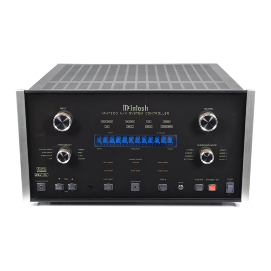
A/V SYSTEM CONTROLLER
Performance Specifications ................................... 2 - 3
Notes ......................................................................... 3
Rear Panel .................................................................. 4
Section Location ........................................................ 4
Block Diagram ...................................................... 5 - 7
Interconnection Diagram .................................... 8 - 10
Display Schematic and PCB ............................... 11 - 18
Keyboard Schematic and PCB ....................... 13, 17 - 18
Bottom Schematic and PCB ................................ 19 - 24
Power Supply Schematic and PCB ..................... 25 - 28
Data2 Schematic and PCB ................................. 29 - 32
Data1 Schematic and PCB ................................. 33 - 36
CONTENTS
SERVICE MANUAL
Digital Schematic and PCB ................................ 37 - 40
S-Video Schematic and PCB .............................. 41 - 52
Composite Video Schematic and PCB ............... 53 - 58
Main Audio Schematic and PCB ....................... 59 - 74
Multi Channel Schematic and PCB .................... 75 - 86
Amplifier Schematic and PCB .......................... 89 - 104
Tuner AM/FM Alignment Procedure ............. 105 - 106
Tuner/RAA1 Schematic and PCB ................... 107 - 110
DSP Module PCB ................................................... 111
Backup Power Supply ............................................ 112
Exploded Views and Parts Lists ...................... 113 - 114
Repacking Instruction ............................................ 115
Advertisement
Table of Contents

Related Manuals for McIntosh MHT200


Summary of Contents for McIntosh MHT200
-
Page 1: Table Of Contents
A/V SYSTEM CONTROLLER CONTENTS Performance Specifications ........2 - 3 Digital Schematic and PCB ........ 37 - 40 Notes ................. 3 S-Video Schematic and PCB ......41 - 52 Rear Panel ..............4 Composite Video Schematic and PCB ....53 - 58 Section Location ............ -
Page 2: Performance Specifications
Maximum Input Signal 230 Volts, 50/60Hz at 3.5 Amps Analog Input: 6Vrms 240 Volts, 50/60Hz at 3.5 Amps Note: Refer to rear panel of the MHT200 for the correct voltage. Tone Controls +/-12dB from the flat setting Dimensions Front Panel: 17-3/4 inches (45.09cm) wide, 9-7/16 inches If any of the channels have the Loudspeaker Setting of Small, the (23.97cm) high. -
Page 3: Notes
MHT200 PERFORMANCE SPECIFICATIONS con’t FM Tuner RF Intermodulation 65dB Useable Sensitivity 14dBF which is 1.4uV across 75 ohms Stereo Separation 45dB at 100Hz 50dB Quieting Sensitivity 45dB at 1,000Hz Mono: 19dBF which is 2.4uV across 75 ohms 35dB at 10,000Hz... -
Page 4: Rear Panel
REAR PANEL SECTION LOCATIONS MAIN COMPOSITE S-VIDEO DIGITAL DATA1 RAA1 MODULE VIDEO PCB TUNER RAA1 DATA2 (OPTIONAL) BACKUP MULTI POWER SUPPLY CHANNEL BOTTOM POWER SUPPLY PCB (BACK) PCB (FRONT) TOP VIEW WITH COVER REMOVED SEE INTERCONNECT 14 15 16 DISPLAY KEYBOARD... -
Page 5: Block Diagram
MHT200 BLOCK DIAGRAM VIDEO SWITCHING ON SCREEN DISPLAY MODULE POWER SUPPLY OSD ON/OFF VIDEO BACKUP MONITOR A SWITCH POWER SUPPLY COAX VIDEO -15V MONITOR B COAX DRIVER DIGITAL DIGITAL ZONE COMPOSITE OUTPUTS INPUT OPTICAL A AND B VIDEO OPTICAL SWITCHING... - Page 6 INTERCONNECT SLOTSELECT SERIALCLK MISO -INTERRUPT MOSI -RESET OUT1 OUT3 MIC+ DISPLAY OUT2 IRDATA IDENTCLK IDENTDATAOUT PG_LIGHT4 PG_LIGHT1 BULB1 BULB2 PG_LIGHT3 PG_LIGHT2 320149SP BULB1 BULB2 BULB2 PG_LIGHT2 PG_LIGHT3 BULB1 PG_LIGHT1 PG_LIGHT4 FIL1 FIL2 +12V -29V -15A +15A JACKSW POWER HP_R 6VAC1 HP_L RELAY DRV 120V...
- Page 7 MHT200 DISPLAY 320167 SH 1 OF 4 LatchIn LL4148 Manual latching +5D_2 +5D_2 LateNight On the snap-off board Data Input TrimUp +5D_2 +5D_2 +5D_2 100n 100n 100n +5D_2 TrimDown IC10 100n +5D_2 100n ZoneB 100n SH/DL SysOff 100n Standby 100n...
- Page 8 Scope hooks, power for prototyping etc. R101 R102 R103 R111 MOUNTING HOLE MOUNTING HOLE MH13 X2P1M X2P1M X2P1M Not Installed Not Installed Not Installed MOUNTING HOLE MOUNTING HOLE MH10 X2P1M X2P1M LOGO1 Not Installed Not Installed McIntosh MOUNTING HOLE MCINTOSH_LOGO...
- Page 9 MHT200 DISPLAY 320167 SH 3 OF 4 R134 not installed 300R R135 not installed MOLDfor selector leds MOLDfor selector leds MOLDfor selector leds MOLDfor selector leds R143 300R not installed R136 300R R119 100n Expand 300R 300R CenterSpkr SurrSpkr SubW...
- Page 10 DISPLAY 320167 SH 4 OF 4 AND +15A_2 100n Not Installed 100n -15A_2 +15A_2 R115 100k R116 AD Electronics 3052-40 Mic+d IC21A TL072 R113 R114 100k 100k -15A_2 IC21B TL072 +5D_2 +5D_2 LL4148 HP_Rd JackSwd HP_Ld not installed AD Electronics 3052-40 LL4148 JackSwd HP_Rd...
- Page 11 MHT200 BOTTOM 320168 SH 1 OF 2 +15A +5Va Option1 +5Va +15A Option2 +15A Not Installed Bulb1 FERRITE BEAD NotInstalled NotInstalled -15A -5Va 100n 100n 180k BC858 Bulb1 NotInstalled BC848 D2 NotInstalled OptionalRelayfor +/-15V BC858 100n analog 100n ground 390k...
- Page 12 BOTTOM 320168 SH 2 OF 2 JackSw HP_R HP_L Main_L +5Va -5Va DigInM_BBconn Main_C Main_R DigInP_BBconn Main_Ls Channel9_BB Main_Rs Main_Lb Channel10_BB +5Va IR Data A +5V Main_Rb Amp_z_R SEL_0 +15A Amp_z_L OE_0 Out2 IR Data B +5V Main_Sw FP_IRdata IRdata MISO DigitalOK Select 0...
- Page 13 MHT200 BOTTOM 320168...
- Page 14 POWER SUPPLY 320131 500mA 1.6A F1 = T1.6AL 250V F2 = T500mAL 250V...
- Page 15 MHT200 POWER SUPPLY 320131...
- Page 16 DATA2 320123 Component Video NFM51R10P157 IN1B Output B OUTB BAS70-04 Output G 100k OUTG Output R OUTR Informs GenV from which zone IR data is received +5V = zone A, 0V = zone B Shield CHOKE Input 1 B HSP-243V3-47 Active low reset Reset CHOKE...
- Page 17 MHT200 DATA2 320123...
- Page 18 DATA1 320122...
- Page 19 MHT200 DATA1 320122...
- Page 20 DIGITAL 320126 DigitalOutput CoaxOut CoaxGnd Digitalin F Coaxial Input Buffers 100n Shield 100p HSP-252V3-23 100n Digital Input Selection 100n Input B+ 14 1 Input A+ Input B- 15 Input A- 100p Output B 13 Output A VCC 16 input0 Input D+ 10 Input C+ input1 Digital in E...
- Page 21 MHT200 DIGITAL 320126...
- Page 22 S-VIDEO 320125 SH 1 OF 5...
- Page 23 MHT200 S-VIDEO 320125 SH 2 OF 5...
- Page 24 S-VIDEO 320125 SH 3 OF 5...
- Page 25 MHT200 S-VIDEO 320125 SH 4 OF 5...
- Page 26 S-VIDEO 320125 SH 5 OF 5...
- Page 27 MHT200 S-VIDEO 320125...
- Page 28 COMPOSITE VIDEO 320124 SH 1 OF 2...
- Page 29 MHT200 COMPOSITE VIDEO 320124 SH 2 OF 2...
- Page 30 COMPOSITE VIDEO 320124...
- Page 31 MHT200 MAIN AUDIO 320165 SH 1 OF 7 TunerL Audio In 1 (external/internal tuner) TunerR -15A AInL1 Not Installed 100k IC2A AInR1 Zone A Out TL072 Note: Fixed, feeds an external processor. Hence no mute circuitry. +15A 100k Not Installed...
- Page 32 MAIN AUDIO 320165 SH 2 OF 7 Mute relay C271 R210 ZoneB_L Amp_z_L MCS2H-S BC848B/BCW32 Zone B Audio OUT EXC ML C263 68R/100MHZ 3A 100u Installed KP21 100n 100k R173 LL4148 MrMute C272 R212 C132 100n ZoneB_R Amp_z_R C262 KP22 100k Installed RecVCR2 L Out...
- Page 33 MHT200 MAIN AUDIO 320165 SH 3 OF 7 Control signal outputs Slot 4 (multiroom/zone) C139 R114 R115 100n R116 IC42 R109 R113 C138 100n MrSClk MrMOSI SERIN MrSrcSel0 MOSI MrMOSI MrSrcSel1 Out1 MrLatchOut MrSClk SRCLK MrSrcSel2 Out2 MrVolCs SRCLR MrVcMute...
- Page 34 MAIN AUDIO 320165 SH 4 OF 7 C163 100n Module connector (digital) -reset IC49B C164 Interrupt to processor 74HC04 100n MODULE1A IC49A 74HC04 Out1 Out1 SPI-MISO MISO Out2 Out2 SPI-SCK SPI-MOSI MOSI SPI-/Sel data/-addr R121 HREQ Out3 DGND DGND IRdata IC62 DGND 74HC30...
- Page 35 MHT200 MAIN AUDIO 320165 SH 5 OF 7 Motherboard data write R143 R144 C175 IC46 100n C174 IC39 100n SERIN AnalogSelect0 AnalogSelect1 SRCLK AnalogSelect2 MOSI SRCLR Mic_ON Out1 DigitalSelect0 Out2 RCLK DigitalSelect1 DigitalSelect2 MISO DigitalOK (Acknowledge active status) R142 SEROUT...
- Page 36 MAIN AUDIO 320165 SH 6 OF 7 +15A +5Va Module Connector (power) 50uH C252 C189 C191 LL4148 +15A 100n 100n MODULE1C +5Va_module +5 Dig. +15 An. -15A +5Va C253 +5 Dig. +15 An. C190 C192 1000u 1000u 1000u 100n 100n DGND -15 An.
- Page 37 MHT200 MAIN AUDIO 320165 SH 7 OF 7 Slot 2 (videoboard) Slot 3 (multichannel io) Slot 0 (motherboard) slot hw number=1: Motherboard rev2 ID=5 C228 ID=10 IC16 100n IC25 100n IC56 100n -reset SH/DL -reset SH/DL -reset SH/DL IdentClk IdentClk...
- Page 38 MAIN AUDIO 320165 TUNER DSP MODULE VCR1 VCR2 ZONEA VCR1 REC VCR2 REC ZONEB...
- Page 39 MHT200 MULTI CHANNEL Multichannel switching, left channel 100p 320169 SH 1 OF 6 External 7.1 Inputs +15A -15A -15A Ext_L L In BP_LIn 100p 100n 100n 100k IC1A Not Installed TL072 +15A Not Installed R In BP_RIn Ext_R McSClk SCLK...
- Page 40 MULTI CHANNEL 320169 SH 2 OF 6 C207 R157 C206 100n 100k IC31A 100n IC32A JackSw ³1 C215 Board-toBoard Connector bb_Reset INTERRUPT LL4148 470p JackSw +15A HP_R HP_L C222 74HC74 Sw_L Rx/Cx Sw_C 220n C203 Sw_R 100u C209 74HC4538 Sw_Ls SW_9 100n Sw_Rs...
- Page 41 MHT200 MULTI CHANNEL 320169 SH 3 OF 6 Relay Drive BLM31A601S C196 100u bb_Zone_L Mute relays Amp_Zone_L Out_L 100u Power Amp Connector 100k Relay Drive 7.1 Outputs MCS2H-S BC848/BCW32 Not Installed Amp_L BP_LOut C101 100n Amp_C Amp_R HSP-243V3-48 L Out...
- Page 42 MULTI CHANNEL 320169 SH 4 OF 6 +5Va C218 Not Installed 100n BLM31A601S R227 R225 Main L+R -15A -15A Phones out -15A Out_L 220n Vol_L IC3A 220n TL072 +15A IC8A OPA2134 IC7A HP_L LGND OPA2134 Not installed +15A Not installed C219 Not Installed RGND...
- Page 43 MHT200 MULTI CHANNEL 320169 SH 5 OF 6 Surround L+R +5Va C124 Not Installed 100n -15A +15A BLM31A601S V1.1 C147 C149 -15A +15A -15A 100n 100n C152 C153 100n 100n -15A 220n 220n Vol_Ls IC19A TL072 +15A Out_Ls LGND IC4A...
- Page 44 MULTI CHANNEL 320169...
- Page 45 MHT200 NOTES...
- Page 46 AMPLIFIER 320129 (FRONT & BACK) SH 1 OF 7...
- Page 47 MHT200 AMPLIFIER 320129 (FRONT & BACK) SH 2 OF 7...
- Page 48 AMPLIFIER 320129 (FRONT & BACK) SH 3 OF 7...
- Page 49 MHT200 AMPLIFIER 320129 (FRONT & BACK) SH 4 OF 7...
- Page 50 AMPLIFIER 320129 (FRONT & BACK) SH 5 OF 7...
- Page 51 MHT200 AMPLIFIER 320129 (FRONT & BACK) SH 6 OF 7...
- Page 52 AMPLIFIER 320129 (FRONT & BACK) SH 7 OF 7...
- Page 53 MHT200 AMPLIFIER 320129 (FRONT & BACK)
-
Page 54: Tuner Am/Fm Alignment Procedure
Note: Trimmer Capacitor C106 (AM jacks. (These jacks act as the Tuner Output.) Connect a Distortion Analyzer to the MHT200 rear panel 3. Remove Top Cover and AM/FM TUNER Cover. Turn On AMT) is located on the RAA1. It is labeled “C1”. - Page 55 MHT200 TUNER 049084 105 - 106...
- Page 56 TUNER RAA1 SECTION 049084 NOTE: SEE PAGE 105 - 106 FOR TUNER ALIGNMENT PROCEDURES...
-
Page 57: Dsp Module Pcb
BACKUP POWER SUPPLY 320166 320149 COMPONENT SIDE VIEW 5.3V ADJUSTMENT LOWER HIGHER FRONT REAR PANEL PANEL +5.3VDC SET R1 FOR 5.3VDC AT PIN 2 OF CONNECTOR CN2 FLASH NOTE BEVELED CORNER 133506SP = BLANK IC 133507SP = MHT200 V6.44 PROGRAMMED IC... - Page 58 MHT200 EXPLODED VIEW and PARTS LIST 016489 GLASS 148073 SWITCH DPDT ROCKER 017531 PUSHBUTTON ASSY RED 017517 PUSHBUTTON ASSY BLK 078033 O-RING 017938 BEZEL PUSHBUTTON 017852 PUSHBUTTON BLK 078032 O-RING 017741 RECEPTACLE PUSHBUTTON 017854 BEZEL HEADPHONE 049600 ASSY KNOB 25.5mm...
-
Page 59: Repacking Instruction
101169 #10 x 2-1/4” Wood screw is needed, please call or write the Customer Service 104033 #10 x 1-3/4" Flat washer Department of McIntosh Laboratory. Order parts from 034159 Foam end caps the accompanying list by part number. 034158 Shipping carton... -
Page 60: Service Manual
SERVICE MANUAL The continuous improvement of its products is the policy of McIntosh Laboratory Incorporated, who reserve the right to improve design without notice. Because of the constant upgrading of McIntosh products’ circuitry and components, the Company cannot insure, and does not warrant, the accuracy of the within schematic material, which is intended for information only.
Need help?
Do you have a question about the MHT200 and is the answer not in the manual?
Questions and answers