Table of Contents
Advertisement
Quick Links
WALL HUNG FAN FLUE
ROOM SEALED GAS COMBINATION BOILER
MODEL
British Gas Tested and Certified
G. C. No. 47 116 01
This boiler is for use with natural gas only
LEAVE THESE INSTRUCTIONS
ADJACENT TO THE GAS METER
BIASI U.K. Ltd
Unit 41, Planetary Road Industrial Estate, Neachells Lane
Willenhall, Wolverhampton WV13 3XB
Telephone: 01902 304400 --- Fax: 01902 304321
Advertisement
Table of Contents

Related Manuals for Savio 20/1 MFS

Summary of Contents for Savio 20/1 MFS
- Page 1 G. C. No. 47 116 01 This boiler is for use with natural gas only LEAVE THESE INSTRUCTIONS ADJACENT TO THE GAS METER BIASI U.K. Ltd Unit 41, Planetary Road Industrial Estate, Neachells Lane Willenhall, Wolverhampton WV13 3XB Telephone: 01902 304400 --- Fax: 01902 304321...
-
Page 2: Table Of Contents
......6.12 Ignition and/or detection electrodes ..Short spare parts list ....boiler 20/1 MFS... -
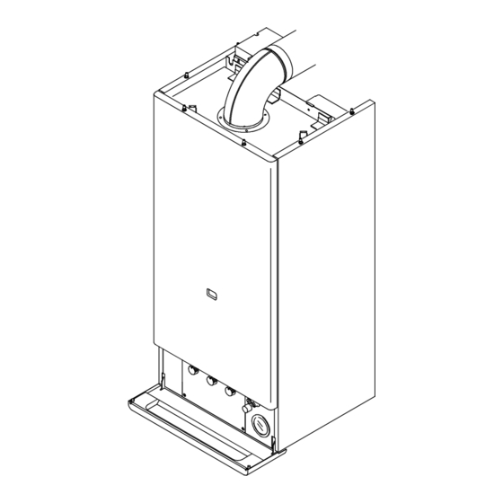
Page 3: General Information
GENERAL INFORMATION Overall view (16) Front view Rear view (17) Main heat exchanger 24 Flue gas sampling point Manual vent cock 25 Air pressure switch 26 Expansion vessel Combustion chamber 27 Data badge Burner 28 Gas inlet Overheat thermostat (probe) 29 Central heating (c.h.) water return Detection electrode 30 C.h. -
Page 4: Technical Data
General information Technical data Gas requirements Heat input: max gas rate 2,79 m 98,5 ft 28,74 kW 98 080 Btu/h min gas rate 1,04 m 36,7 ft 12,40 kW 42 317 Btu/h Inlet pressure 20 mbar 7,9 in w.g. Heat output: Burner pressure: 23.25 kW 79 344 Btu/h... -
Page 5: Description
More than one section may be used but the total length of the exhaust duct must not exceed 3 m (9,84 ft). fig. 1.2 The boiler 20/1 MFS is a combined central heating Every section allows to extend the duct by 825 mm (c.h.) and domestic hot water (d.h.w.) appliance. -
Page 6: Design Principles And Operating Sequence
General information Supplementary elbow Main heat exchanger Main circuit C.h. circuit flow switch By--- pass Pump fig. 1.6 fig. 1.4 During operation as a d.h.w. heater, the main water cir- A single supplementary elbow only, can be used during cuit is directed through the d.h.w. heat exchanger (see installation: the length of the exhaust duct (standard fig. - Page 7 General information not sense the correct velocity, the burner will shut --- when the temperature of the c.h. water is less than down. the preset temperature by a ? t value (difference be- tween output and input temperature) between 6 ° C Operating sequence on central heating mode and 15 °...
-
Page 8: General Requirements
GENERAL REQUIREMENTS This appliance must be installed by a competent The location must permit the provision of an adequate person in accordance with the Gas Safety (installa- flue and termination. tion & Use) Regulations 1984. For unusual locations special procedures may be necessary and BS 6798---1987 gives detailed guidance Related documents on this aspect. -
Page 9: Air Supply
General requirements boiler and the other appliance when they are in use at Where possible pipes should have a gradient to ensure the same time. air is carried naturally to air release points and water flows naturally to drain taps. Pipework must be of adequate size. -
Page 10: Domestic Water
There must be no direct connection to the mains water apply. supply even through a non return valve, without the ap- The boiler 20/1 MFS is supplied for connection to a proval of the Local Water Authority. 240 V~ 50 Hz supply. The supply must be fused at 3A. -
Page 11: Installation
INSTALLATION Delivery There will be 3 items: the boiler fully assembled; the wall mounting bracket with cocks and pipes; Standard flue assembly which include flue pipes and 90° elbow. Measurements for installing the appliance (5,12) Wall mounting bracket 400 (15,7) (5,12) 187 (7,36) 213 (8,38) -
Page 12: Assembling The Wall Mounting Bracket
installation Assembling the wall mounting bracket The carton marked wall mounting bracket contains the following: mounting bracket; 1/2”cock for d.h.w. inlet; 3/4”cocks for c.h. flow and return; 1/2”nipples for d.h.w. and safety valve outlet; 3/4”gaskets; 3/4”nuts for mounting 3/4” cocks and gas pipe; 3/4”nipple for c.h. -
Page 13: Unpacking The Boiler
Installation --- mount the cock for gas inlet (18) and the 3/4 ” cock for c.h. return (3). Be sure to use the correct gaskets. --- mount the pipe for c.h. return (9); Wall mounting bracket (1) (front view) --- mount the safety valve (14) on the c.h. return pipe (13) with a Towards the 1/2”gasket. -
Page 14: Mounting The Boiler On The Bracket
installation --- lift up the carton; --- rest the boiler on the floor and remove the polystyrene guards. Mounting the boiler on the bracket --- Remove the protection caps from the pipes on the boiler; --- carefully clean the cocks and connections mounted on the wall mounting bracket;... -
Page 15: Mounting The Flue Exhaust Pipes
Installation Mounting the flue exhaust pipes Open the carton marked standard flue exhaust pipes. It contains the following: 19 flue exhaust pipe with wind---resistant terminal; 20 pipe support 21 self---tapping screws 3,5 x 19 mm; 22 springs for the tightening band; 23 gasket tightening band;... - Page 16 installation Mounting operations --- Insert the exhaust pipe into the suction pipe so that the wind--- resistant terminal contacts the rim which is located on the inside of the suction pipe; --- introduce the pipe assembly, together with wind---resistant ter- minal, into the hole you have drilled in the wall.
-
Page 17: Flue Terminal Guard
Installation Flue terminal guard Where codes of practise dictate a suitable guard should be fitted. A suitable guard is available from: TOWER FLUE COMPONENTS Morley Road Tonbridge Kent TN9 1RA When ordering guard, quote appliance model number. The guard should be fitted centrally over the terminal. Electrical connections Connecting to the electricity supply WARNING -- THIS APPLIANCE MUST BE EARTHED... - Page 18 installation --- unscrew the four screws ” E”and remove the cover on the full sequence control p.c.b. --- remove the cable sliding it through the rubber grommet ” F” ; --- insert the new cable. A PVC insulated flexible cable must be used.
-
Page 19: Commissioning
COMMISSIONING Electrical installation Preliminary electrical system checks to ensure electrical safety shall be carried out by a competent person. I.e. polarity, earth continuity, resistance to earth and short circuit. If a fault has occurred on appliance the fault finding procedure should be followed as specified under the servicing section of this document. -
Page 20: Setting The System Pressure
Commissioning When the installation and filling are completed turn on the cen- tral heating system (sect. 4.6) and run it until the temperature has reached the boiler operating temperature. The system must then be immediately flushed through. The flushing procedure must be in line with BS7593: 1992 Treat- ment of Water in Domestic Hot Water Central Heating Systems. -
Page 21: Checking The Gas Pressure At The Burner
Commissioning Checking the gas pressure at the burner Checking maximum and minimum pressure levels Remove the front panel of the case and lower the control panel (sect. 6.2); remove the screw (indicated) on the pressure test point for measuring outlet pressure at the gas valve and fit a pressure gauge using a hose;... -
Page 22: Checking The Flue System
Commissioning Checking the maximum rate for central heating Btu/h 14 Turn the function switch as shown in sect. 4.6; 78 491 15 check the maximum gas pressure and refer to the diagram 71 666 shown here to determine pressure for the heating output you 64 841 need;... -
Page 23: Instructing The User
Commissioning The pump may operate when activated by an external control device (room thermostat and/or timeclock). This operating mode is obtained by connecting a link between ter- minals P2 and PC. The appliance is tested and delivered in this operating mode The pump may only operate when a request for heat lights up the main burner. -
Page 24: Maintenance
MAINTENANCE General Visually check the flue system checked for sound- ness. Check all clamps, gaskets and fixings are se- To ensure efficient safe operation of the appliance it is cure and tight. To check the exhaust gas, remove necessary to carry out routine maintenance at regular the screw indicated in fig. -
Page 25: Servicing Instructions
SERVICING INSTRUCTIONS Replacement of parts The life of individual components varies and they will need servicing as and when faults develop. The fault finding sequence charts in chapter 7 will serve to locate which component is the cause of any malfunction, and instructions for removal, inspection and replacement of the individual parts are given in the following pages. -
Page 26: To Drain The Main Circuit Of The Boiler
Servicing instructions Removing the sealed chamber cover To open the sealed chamber remove the front panel and the right panel of the case then turn the four clamps as indicated and remove the cover. When replacing the sealed chamber cover ensure that the seal is made good. -
Page 27: To Drain The D.h.w. Circuit Of The Boiler
Servicing instructions To drain the d.h.w. circuit of the boiler Close the cold water inlet cock; open the drain tap of d.h.w. system or a draw ---off tap; open the d.h.w. circuit drainage cock indicated. Setting gas pressures IMPORTANT minimum gas pressure mut be set after maximum setting. Open the boiler and operate as explained in sect. -
Page 28: Electronic Regulation P.c.b
Servicing instructions turn the c.h. temperature adjustment to its maximum position as indicated; remove the service access doors (sect. 6.2); Do not change position of knobs during operations. lower the control panel (sect. 6.2) remove the screw on the pressure test point for measuring outlet pressure at the gas valve and fit a pressure gauge using a hose (step 2 at page 19);... -
Page 29: Overheat Thermostat
Servicing instructions disconnect the electrical connectors ” B” ; remove the screw ” C” which hold the electronic regulation p.c.b; remove the circuit board; reassemble in reverse order. To reassemble correctly the electric wires and connectors look at the wiring diagram in sect. 8.1 or at the diagram stuck on the inner cover of the control panel. -
Page 30: Injectors
Servicing instructions 6.11 Injectors Remove the burner (sect. 6.10); unscrew injectors; reassemble in reverse order. Removing injectors, metallic gaskets must be replaced. 6.12 Ignition and/or detection electrodes Remove the burner (sect. 6.10); unscrew the screws ” A”and remove the electrodes; reassemble in reverse order. -
Page 31: Gas Modulator Coil
Servicing instructions with a 14 mm spanner turn the cartridge ” B” counter-clockwise; remove the cartridge; reassemble in reverse order. 6.15 On---off operator coils Ensure electricity is switched off at main isolator; remove the front panel of the case and lower the control panel (sect. -
Page 32: Gas Valve
Servicing instructions 6.17 Gas valve Ensure electricity is switched off at main isolator; remove the front panel of the case and lower the control panel (sect. 6.2); remove the connectors ” A”to the gas modulator; loose the screw ” B” and remove the connectors ” C”and ” D”to the on---off operators;... -
Page 33: Air Pressure Switch
Servicing instructions 6.19 Air pressure switch Ensure electricity is switched off at main isolator; loosen the three screws ” A” and open the box which houses the air pressure switch; this box is located on the upper left---hand side of the appliance; disconnect the electrical connectors ”... -
Page 34: Main Circuit Flow Switch
Servicing instructions Re-- assembling the pump Carefully clean the supporting seat for the flat gasket; correctly position the gasket in the seat on the volute (scroll); correctly position the pump and the mounting flange; insert the four mounting screws; tighten the four screws until they meet resistance but do not allow the screws to exert any uneven pressure whatsoever on the flange;... -
Page 35: Temperature
Servicing instructions 6.25 Temperature ---pressure gauge Ensure electricity is switched off at main isolator; remove the front panel and the right panel of the case and lower the control panel (sect. 6.2); drain the main circuit (sect. 6.3); with a suitable fork spanner hold the connector ” A” and unscrew the nut ”... -
Page 36: Safety Valve
Servicing instructions remove the upper protection plate by loosening the screw ” A” which holds the plate to the chassis; remove the screws ” B”and move the box containing the air pressure switch toward the front of the appliance; remove the upper bolt which attaches the expansion vessel to the transverse bar on the chassis;... -
Page 37: Heat Exchanger
Servicing instructions 6.31 D.h.w. heat exchanger The d.h.w. heat exchanger may be carried out in two ways, accord- ing to the manner in which the appliance is installed: --- from the top if at least 40 cm (15,7 ins) of free space are available between the appliance and any obstacle above the appliance;... - Page 38 Servicing instructions Removing the plug Automatic air release valve Remove the d.h.w. heat exchanger; slacken the automatic air release valve remove the fork; use a screwdriver to pry between the shell and the air release fork valve at a number of different points; lift the plug and the valve upwards.
-
Page 39: Temperature Probe
Servicing instructions Re-- assembling the d.h.w. heat exchanger Position the O---ring gaskets on the lower end of the bellows; insert the bellows into the shell and use the plug, without O--- rings, to force the bellows into its final position; install the plug as previously explained;... -
Page 40: Water Unit
Servicing instructions Complete substitution of the flow switch Ensure electricity is switched off at main isolator; remove the front panel of the case, the lower protection plate and lower the control panel (sect. 6.2); drain the d.h.w circuit (sect 6.4); remove the connectors ”... - Page 41 Servicing instructions loosen the outlet connector of the main heat exchanger; remove fork ” C”which holds the connecting pipe to the main heat exchanger and move the pipe away from the water devi- ation body; disconnect the pressure gauge connecting pipe by removing the fork ”...
-
Page 42: O---Rings Position On The D.h.w. Heat Exch
Servicing instructions 6.35 O---rings position on the d.h.w. heat exchanger Plug Bellows All O---rings are illustrated in real size rev. 17.09.93... -
Page 43: Fault Finding
FAULT FINDING Fault finding diagrams Make sure that the main circuit pressure gauge is cor- rectly reading the amount of water being used. Remove The fault finding diagrams illustrate the proper steps to the d.h.w. heat exchanger and check the bellows for be followed when searching for the cause of improper leaks. -
Page 44: Appliance Completely Shut Down
Fault finding Appliance completely shut down Initial conditions: --- the function switch is on position --- the thermostat or timer is calling for heat ref. 1; --- sufficient gas is being fed to the boiler. Start Switch on the main isolator --- electrical power line is faulty;... - Page 45 Fault finding ref. 7 Disconnect the terminals from the microswitch on the flow switch and measure the resistance. When the ref. 1 Supply voltage should be indicated when the appliance is switched off the resistance should be in- appliance is started and when the thermostat or timer finity;...
-
Page 46: Fault Of Full Sequence Control P.c.b
Fault finding Fault of full sequence control p.c.b. Start Is power being --- open circuit in one of Does the shut--- down supplied to the full se- the cables to the device; warning light indicate quence control p.c.b? ref. 13. a shut--- down? ref. - Page 47 Fault finding ref. 12 Supply voltage should be indicated when power is supplied to the device. Set tester to VAC. ref. 17 Disconnect the connector from the device and measure the resistance.The tester should indicate zero ohms when the microswitch is actuated. Set tester to ohm.
-
Page 48: Fault On D.h.w
Fault finding 7.10 Fault on d.h.w. --- c.h. switching Initial conditions: --- the function switch is in position. --- the thermostat or timer is calling for heat ref. 23. --- The lever on the 3---way valve is set to ” automatic” ; ref. - Page 49 Fault finding ref. 27 Power is being supplied to the 3---way valve when sup- ply voltage is measured across the points shown in the ref. 23 Supply voltage should be indicated when the diagram. Set the tester to VAC. appliance is started with an open thermostat or timer. Set the tester to VAC.
-
Page 50: Fault On Modulation
Fault finding 7.11 Fault on modulation Initial conditions: --- C.h. and d.h.w. temperature adjustments on maximum position. --- Low temperature on c.h. and d.h.w. circuits. Start Turn the function switch on Turn the c.h. and d.h.w. tempera- ture adjustments on minimum position. - Page 51 Fault finding ref. 31 Check the gas pressure at the test point for measuring outlet pressure at the gas valve and compare with the value on sect. 1.2. ref. 32 Check the gas pressure at the test point for measuring inlet pressure at the gas valve and compare with the value on sect.
-
Page 52: Electric Diagrams
ELECTRIC DIAGRAMS General wiring layout AIR PRESSURE SWITCH D.H.W TEMPERATURE PROBE AIR PRESSURE SWITCH BOX DETECTION ELECTRODE IGNITION RESET VALVE ELECTRODE PUSH BUTTON SHUT DOWN WARNING LIGHT OVERHEAT THERMOSTAT FULL SEQUENCE CONTROL P .C.B. D.H.W. FLOW SWITCH ELECTRONIC MAIN REGULATION P .C.B. CIRCUIT FLOW SWITCH... -
Page 53: Functional Flow Diagrams
Electric diagrams Functional flow diagrams General layout L --- LINE N --- NEUTRAL function switch position: off ACTIVATED CIRCUIT NON ACTIVATED CIRCUIT F2 (1,6 A T) F1 (0,08 A T) TRANSFORMER TB1--- L J1--- 4 21V= TO THE LOW VOLTAGE PUMP SECTION OF THE PRESSURE SWITCH... - Page 54 Electric diagrams Function switch position L --- LINE N --- NEUTRAL Heat request on c.h. ACTIVATED CIRCUIT NON ACTIVATED CIRCUIT F2 (1,6 A T) F1 (0,08 A T) TRANSFORMER TB1--- L J1--- 4 21V= TO THE LOW VOLTAGE PUMP SECTION OF THE PRESSURE SWITCH REGULATION P .C.B.
- Page 55 Electric diagrams Function switch position L --- LINE N --- NEUTRAL Heat request on d.h.w. ACTIVATED CIRCUIT NON ACTIVATED CIRCUIT F2 (1,6 A T) F1 (0,08 A T) TRANSFORMER TB1--- L J1--- 4 21V= TO THE LOW VOLTAGE PUMP SECTION OF THE PRESSURE SWITCH REGULATION P .C.B.
- Page 56 Electric diagrams Function switch position L --- LINE N --- NEUTRAL Heat request on d.h.w. ACTIVATED CIRCUIT NON ACTIVATED CIRCUIT F2 (1,6 A T) F1 (0,08 A T) TRANSFORMER TB1--- L J1--- 4 21V= TO THE LOW VOLTAGE PUMP SECTION OF THE PRESSURE SWITCH REGULATION P .C.B.
-
Page 58: Short Spare Parts List
SHORT SPARE PARTS LIST Key G.C. part Description Manufacturer’ s No. Manuf. reference Part No. 164 080 12 ramps burner KG2004 101 379 102 Injectors (including copper gaskets) Polidoro ø1.35 mm 12 KG2004 106 379 083 Gas modulator cartridge SIT Control 0.928.850 KG2004 117 379 081 Gas valve SIT Control 827 Nova 0.827.150... - Page 59 Short spare parts list boiler 20/1 MFS rev. 17.09.93...
Need help?
Do you have a question about the 20/1 MFS and is the answer not in the manual?
Questions and answers