
Related Manuals for Crestron MPC-M10


Summary of Contents for Crestron MPC-M10
- Page 1 Crestron MPC-M10/20/25 MPC Media Presentation Controller™ Operations & Installation Guide...
-
Page 2: Regulatory Compliance
This product is Listed to applicable UL Standards and requirements by Underwriters Laboratories Inc. As of the date of manufacture, the MPC-M10/2/25 has been tested and found to comply with specifications for CE marking and standards per EMC and Radiocommunications Compliance Labelling. -
Page 3: Table Of Contents
Crestron MPC-M10/20/25 Media Presentation Controller Contents MPC Media Presentation Controller™: MPC-M10/20/25 Introduction ..........................1 Features and Functions ....................1 Applications......................... 4 Specifications ......................6 Physical Description....................8 Setup ............................15 Network Wiring......................15 Identity Code ......................15 Supplied Hardware ....................16 Installation ......................... -
Page 5: Mpc Media Presentation Controller™: Mpc-M10/20/25
5-way directional navigation pad (MPC-M20 and MPC-M25 only) and wireless remote capability. Available in black or white, the MPC-M10/20/25 is constructed to handle the rigors of everyday use in a corporate or educational environment. An assortment of programmable control ports provides connectivity for audio, video and lighting ®... - Page 6 Crestron MPC-M10/20/25 Control…Simplified The MPC-M10/20/25 is engineered to be easy to integrate and use, yet versatile enough to suit each application perfectly. Its “hard key” buttons (10 on the MPC-M10, 15 on the MPC-M20 and MPC-M25) can be freely programmed for system power, input source selection, transport control, lighting presets and any other functions.
- Page 7 Ambient Light Sensor The MPC-M10/20/25’s built-in light sensor has a range of uses, from controlling its own backlight intensity to providing ambient lighting level data to a central building management system.
-
Page 8: Applications
Media Presentation Controller Crestron MPC-M10/20/25 Applications The following diagrams show an MPC-M25 in an education and a business application. MPC-M25 in an Education Application 4 • Media Presentation Controller: MPC-M10/20/25 Operations & Installation Guide – DOC. 6701C... - Page 9 Crestron MPC-M10/20/25 Media Presentation Controller MPC-M25 in a Business Application Media Presentation Controller: MPC-M10/20/25 • 5 Operations & Installation Guide – DOC. 6701C...
-
Page 10: Specifications
Media Presentation Controller Crestron MPC-M10/20/25 Specifications Specifications for the MPC-M10/20/25 are listed in the following table. MPC-M10/20/25 Specifications SPECIFICATION DETAILS Processor ® 32-bit Freescale ColdFire Microprocessor Memory SDRAM 32 MB NVRAM 256 KB Flash 8 MB Operating System Real-time, preemptive multi- threaded/multitasking kernel;... - Page 11 Set of custom engravable backlit labels, (BLANK, ENGRAVED)-W-T black on white 1. The latest software versions can be obtained from the Crestron website. Refer to the NOTE following these footnotes. 2. Crestron 2-Series control systems include the AV2 and PRO2. Consult the latest Crestron Product Catalog for a complete list of 2-Series control systems.
-
Page 12: Physical Description
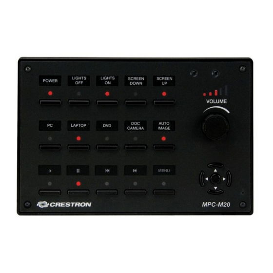
Media Presentation Controller Crestron MPC-M10/20/25 Physical Description This section provides information on the connections, controls and indicators available on your MPC-M10/20/25. MPC-M10 Physical View (Front) MPC-M10 Physical View (Rear) 8 • Media Presentation Controller: MPC-M10/20/25 Operations & Installation Guide – DOC. 6701C... - Page 13 Crestron MPC-M10/20/25 Media Presentation Controller MPC-M20 Physical View (Front) MPC-M20 Physical View (Rear) Media Presentation Controller: MPC-M10/20/25 • 9 Operations & Installation Guide – DOC. 6701C...
- Page 14 Media Presentation Controller Crestron MPC-M10/20/25 MPC-M25 Physical View (Front) MPC-M25 Physical View (Rear) 10 • Media Presentation Controller: MPC-M10/20/25 Operations & Installation Guide – DOC. 6701C...
- Page 15 Media Presentation Controller MPC-M10/20/25 Overall Dimensions (Front View of MPC-M25 Shown) 4.50 in (114 mm) 6.70 in (170 mm) MPC-M10/20/25 Overall Dimensions (Rear and Side Views of MPC-M25 Shown) 0.95 in (24 mm) 2.60 in (66 mm) 1.90 in (48 mm) 2.23 in...
-
Page 16: Connectors/Controls/Indicators
(2) Sets of (4) captive screw terminals; Cresnet port and 24 VDC power input with parallel pass-through; Master/Slave selectable; 24: Power (24 VDC) Data Data G: Ground (Continued on following page) 12 • Media Presentation Controller: MPC-M10/20/25 Operations & Installation Guide – DOC. 6701C... - Page 17 (with shared common); rated 1 A, 30 VAC/DC; MOV arc suppression across contacts DESCRIPTION Common Each pair of inputs shares a common. (Continued on following page) Media Presentation Controller: MPC-M10/20/25 • 13 Operations & Installation Guide – DOC. 6701C...
- Page 18 2. MPC-M20 and MPC-M25 only. 3. MPC-M25 only. 4. MPC-M10 and MPC-M20 have two RELAY ports, MPC-M25 has six RELAY ports. 5. MPC-M10 and MPC-M20 have one IR port, MPC-M25 has two IR ports. 14 • Media Presentation Controller: MPC-M10/20/25...
-
Page 19: Setup
Identity Code Net ID The Net ID of the MPC-M10/20/25 has been factory set to 02. This Net ID is defined as the “Master” control system. The Net IDs of multiple MPC-M10/20/25 devices in the same system must be unique; this means there will be a master/slave relationship between units (only the Net ID of the master will be left at 02). -
Page 20: Supplied Hardware
Media Presentation Controller Crestron MPC-M10/20/25 Supplied Hardware The hardware supplied with the MPC-M10/20/25 is listed in the following table. Supplied Hardware for the MPC-M10/20/25 DESCRIPTION PART NUMBER QUANTITY Mounting Plate with Ground Wire 4506280 Button Identification Labels, Sources, 100 4509400... - Page 21 NOTE: Ensure the unit is properly grounded. 4. Attach cables to the rear of the MPC-M10/20/25. 5. Use the two included 04-40 x 1/4” screws to attach the MPC-M10/20/25 to the mounting plate. CAUTION: Excess wire that is pinched between the MPC-M10/20/25 and the electrical box could short out.
- Page 22 MPC-M10/20/25. 8. Perform any necessary programming using the COMPUTER (USB) connection prior to attaching the front panel of the MPC-M10/20/25. (Programming can also be performed via the LAN port.) 9. Use the four included 04/40 x 1/2” screws and the included 1/16” Allen wrench to attach the front panel to the MPC-M10/20/25.
-
Page 23: Hardware Hookup
Refer to “Network Wiring” on page 15 before attaching the 4-position terminal block connector. Apply power after all connections have been made. When making connections to the MPC-M10/20/25, note the following: • Use Crestron power supplies for Crestron equipment. - Page 24 From Digital or Devices Analog Devices INPUT Connections Depending on the application, the MPC-M10/20/25 INPUTS can be wired multiple ways. Refer to the following diagrams when wiring INPUTS. WARNING: Incorrect wiring may damage the MPC-M10/20/25. 20 • Media Presentation Controller: MPC-M10/20/25...
- Page 25 Pull-up Resistor: Disabled Enabled Label the Buttons Optional custom engraved labels for the MPC-M10/20/25 can be ordered separately by using Crestron Engraver software, available from the Crestron website (www.crestron.com). Media Presentation Controller: MPC-M10/20/25 • 21 Operations & Installation Guide – DOC. 6701C...
-
Page 26: Programming Software
Have a question or comment about Crestron software? Answers to frequently asked questions (FAQs) can be viewed in the Online Help section of the Crestron website. To post a question or view questions you have submitted to Crestron’s True Blue Support, log in at http://support.crestron.com. -
Page 27: Pushbutton Programming
Locating the MPC-M10/20/25 in the Device Library Program Manager Program Manager is the view where programmers “program” a Crestron control system by assigning signals to symbols. The symbol can be viewed by double clicking on the icon or dragging it into Detail View. -
Page 28: Example Program
MPC-M20 and MPC-M25 Pushbutton Layout and Join Assignment (MPC-M25 Shown) Left Enter Right Down Example Program An example program for the MPC-M10/20/25 is available from the Crestron website (www.crestron.com/exampleprograms). 24 • Media Presentation Controller: MPC-M10/20/25 Operations & Installation Guide – DOC. 6701C... -
Page 29: Uploading And Upgrading
PC via a Type A to Type B USB cable (not included). • Use the Address Book in Crestron Toolbox to create an entry using the expected communication protocol (USB). When multiple USB devices are connected, identify the MPC-M10/20/25 by entering (for example) “MPC-M10”... -
Page 30: Programs And Firmware
Crestron Toolbox • Establish USB communication between MPC-M10/20/25 and PC. • Enter the IP address, IP mask and default router of the MPC-M10/20/25 via the Crestron Toolbox (Functions | Ethernet Addressing); otherwise enable DHCP. • Confirm Ethernet connections between MPC-M10/20/25 and PC. If connecting through a hub or router, use CAT5 straight through cables with 8-pin RJ-45 connectors. -
Page 31: Problem Solving
Crestron MPC-M10/20/25 Media Presentation Controller Problem Solving Troubleshooting The following table provides corrective action for possible trouble situations. If further assistance is required, please contact a Crestron customer service representative. MPC-M10/20/25 Troubleshooting TROUBLE POSSIBLE CAUSE(S) CORRECTIVE ACTION Unexpected Network devices are not... -
Page 32: System Monitor
NOTE: If your PC does not have the USB driver installed, after connecting the MPC-M10/20/25 to the PC using the USB cable, you will see a dialog box on your PC screen asking you to install the USB driver. For instructions on how to install the USB driver, refer to the Crestron Toolbox help file. -
Page 33: Check Network Wiring
Cresnet power usage of the entire chain. If the unit is home-run from a Crestron system power supply network port, the Cresnet power usage of that unit is the Cresnet power usage of the entire run. The wire gauge and the Cresnet power usage of the run should be used in the following equation to calculate the cable length value on the equation’s left side. -
Page 34: Reference Documents
Crestron's award winning customer service team by calling Crestron at 1-888-CRESTRON [1-888-273-7876]. You can also log onto the online help section of the Crestron website (www.crestron.com/onlinehelp) to ask questions about Crestron products. First-time users will need to establish a user account to fully benefit from all available features. -
Page 35: Software License Agreement
This Agreement may only be modified by a writing signed by an authorized officer of Crestron. Updates may be licensed to You by Crestron with additional or different terms. This is the entire agreement between Crestron and You relating to the Software and it supersedes any prior representations, discussions, undertakings, communications or advertising relating to the Software. - Page 36 “applets” incorporated into the Software), the accompanying media and printed materials and any copies of the Software are owned by Crestron or its suppliers. The Software is protected by copyright laws and international treaty provisions. Therefore, you must treat the Software like any other copyrighted material, subject to the provisions of this Agreement.
-
Page 37: Return And Warranty Policies
Purchasers should inquire of the dealer regarding the nature and extent of the dealer's warranty, if any. CRESTRON shall not be liable to honor the terms of this warranty if the product has been used in any application other than that for which it was intended or if it has been subjected to misuse, accidental damage, modification or improper installation procedures. - Page 38 Media Presentation Controller Crestron MPC-M10/20/25 This page is intentionally left blank. 34 • Media Presentation Controller: MPC-M10/20/25 Operations & Installation Guide – DOC. 6701C...
- Page 39 Crestron MPC-M10/20/25 Media Presentation Controller This page is intentionally left blank. Media Presentation Controller: MPC-M10/20/25 • 35 Operations & Installation Guide – DOC. 6701C...
- Page 40 Crestron Electronics, Inc. Operations & Installation Guide – DOC. 6701C 15 Volvo Drive Rockleigh, NJ 07647 (2021551) Tel: 888.CRESTRON 07.10 Fax: 201.767.7576 Specifications subject to www.crestron.com change without notice.
Need help?
Do you have a question about the MPC-M10 and is the answer not in the manual?
Questions and answers