Table of Contents
Advertisement
Quick Links
Advertisement
Table of Contents

Related Manuals for Datalogic DS2400N


Summary of Contents for Datalogic DS2400N
- Page 1 DS2400N REFERENCE MANUAL...
- Page 2 Datalogic S.p.A. reserves the right to make modifications and improvements without prior notification. Datalogic shall not be liable for technical or editorial errors or omissions contained herein, nor for incidental or consequential damages resulting from the use of this material.
-
Page 3: Table Of Contents
GENERAL VIEW ..................ix RAPID CONFIGURATION................1 Step 1 – Connect the System ............... 1 C-BOX 100/150 Pinout for DS2400N ............2 Step 2 – Mounting and Positioning the System..........3 Step 3 – X-PRESS™ configuration............... 5 Auto Learn ....................6 Auto Setup (Optional) ................... - Page 4 Accessories....................24 INSTALLATION..................25 Package Contents..................25 Mechanical Installation................26 3.2.1 Mounting DS2400N..................27 3.2.2 Mounting Scanner Accessories..............28 Electrical Connections ................30 3.3.1 Power Supply....................32 3.3.2 Main Serial Interface ................... 32 RS232 Interface ..................33 RS485 Full-Duplex Interface ............... 35 RS485 Half-Duplex Interface ..............
- Page 5 GLOSSARY....................70 INDEX ......................74...
-
Page 6: References
• Genius™ Help On Line SERVICES AND SUPPORT Datalogic provides several services as well as technical support through its website. Log on to www.datalogic.com and click on the links indicated for further information including: • PRODUCTS Search through the links to arrive at your product page where you can download specific Manuals and Software &... -
Page 7: Safety Regulations
LASER SAFETY The following information is provided to comply with the rules imposed by international authorities and refers to the correct use of the DS2400N scanner. Standard Regulations This scanner utilizes a low-power laser diode. Although staring directly at the laser beam momentarily causes no known biological damage, avoid staring at the beam as one would with any very strong light source, such as the sun. -
Page 8: Power Supply
CAUTION-CLASS 3B LASER LIGHT WHEN OPEN AVOID EXPOSURE TO BEAM AVOID EXPOSURE LASER LIGHT Pat. US5992740, EP0789315B1 DATALOGIC AUTOMATION Srl IS EMITTED FROM THIS APERTURE Via S. Vitalino, 13 – 40012 Calderara di Reno MADE IN ITALY-www.datalogic.com Warning and Device Class Labels POWER SUPPLY This product is intended to be installed by Qualified Personnel only. -
Page 9: General View
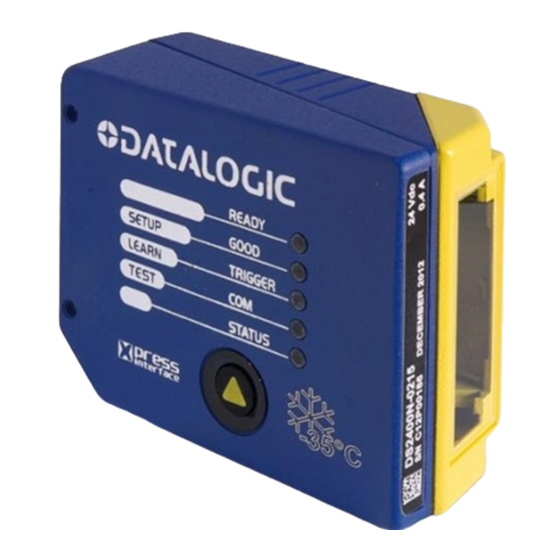
GENERAL VIEW DS2400N Figure A Good LED Warning and Device Class Labels Ready LED Power ON LED Laser Beam Output Window Mounting Holes Status LED Xpress key COM LED Accessory Mounting Holes Trigger LED... -
Page 11: Rapid Configuration
When On-Line Operating mode is used, the scanner is activated by an External Trigger (photoelectric sensor) when the object enters its reading zone. DS2400N CBOX-100/150 Host P.S.* PG 6000 * Presence Sensor (for On-Line mode) Figure 1 – DS2400N in Stand Alone Layout... -
Page 12: C-Box 100/150 Pinout For Ds2400N
C-BOX 100/150 Pinout for DS2400N The table below gives the pinout of the C-BOX 100/150 terminal block connectors. Use this pinout when the DS2400N reader is connected in a network by means of the C-BOX 100/150: C-BOX 100/150 Terminal Block Connectors... -
Page 13: Step 2 - Mounting And Positioning The System
RAPID CONFIGURATION STEP 2 – MOUNTING AND POSITIONING THE SYSTEM To mount the DS2100N, use the mounting bracket to obtain the most suitable position for the reader as shown in the figures below. Skew Tilt Pitch Skew Figure 2 - Positioning with Mounting Bracket When mounting the DS2100N take into consideration these three ideal label position angles: Pitch 0°, Skew 10°... - Page 14 DS2400N Minimize Figure 4 – Tilt Angle Refer to the Reading Diagrams in the Appendix of this Quick Reference Guide to decide the distance your scanner should be positioned at.
-
Page 15: Step 3 - X-Press™ Configuration
RAPID CONFIGURATION STEP 3 – X-PRESS™ CONFIGURATION X-PRESS™ is the intuitive Human Machine Interface designed to improve ease of installation and maintenance. Status and diagnostic information are clearly presented by means of the five colored LEDs, whereas the single push button gives immediate access to the following relevant functions: •... -
Page 16: Auto Learn
DS2400N Auto Learn If you are configuring your scanner using X-PRESS™, you must start with the Auto Learn procedure. Enter the Auto Learn function (F2) by pressing the X-PRESS™ push button. Hold the push button pressed until the F2 LED is on. -
Page 17: Auto Setup (Optional)
RAPID CONFIGURATION Auto Setup (Optional) At the end of the Auto Learn procedure, you have the possibility to follow the Auto Setup procedure to set up the reading parameters. Enter the Auto Setup function (F3) by pressing the X-PRESS™ push button. Hold the push button pressed until the F3 LED is on. -
Page 18: Step 4 - Installing Genius™ Configuration Program
DS2400N STEP 4 – INSTALLING GENIUS™ CONFIGURATION PROGRAM ™ Genius is a Datalogic scanner configuration tool providing several important advantages: • Wizard approach for low skilled users; • Multi-language version; • Defined configuration directly stored in the reader; • Communication protocol independent from the physical interface allowing to consider the reader as a remote object to be configured and monitored. - Page 19 RAPID CONFIGURATION Select the Create a new configuration button. You will be guided through the configuration being asked to define the following parameters: Barcode selection and definition...
- Page 20 DS2400N Operating mode selection and definition Digital Outputs configuration...
- Page 21 RAPID CONFIGURATION Hardware interface selection Output data format configuration The On Line operating Mode requires the reader to be connected to an external Presence Sensor using EXT TRIG/PS A and EXT TRIG/PS B inputs. The Automatic operating mode does not require connection to an external Presence Sensor.
- Page 22 DS2400N After defining the parameter values the following window appears allowing to complete the reader configuration as follows: Saving the configuration to disk; • • Switching to Advanced mode; Sending the configuration to the scanner. • After sending the configuration to...
-
Page 23: Step 5 - Test Mode
STEP 5 – TEST MODE Use a code suitable to your application to test the system. Alternatively, you can use the Datalogic Test Chart (Code 39, Code Interleaved 2/5). Enter the Test mode function (F1) by pressing the X-PRESS™ push button. -
Page 24: Advanced Scanner Configuration
ADVANCED SCANNER CONFIGURATION For further details on advanced product configuration, refer to the complete Reference Manual on the installation CD-ROM or downloadable from the web site through this link: www.datalogic.com/DS2400N. The following are alternative or advanced scanner configuration methods: Host Mode Programming The scanner can also be configured from a host computer using the Host Mode programming procedure, by commands via the serial interface. -
Page 25: Alternative Layouts
The ID-NET™ is a built-in high-speed interface dedicated for high-speed scanner interconnection. ID-NET™ is in addition to the Main and Auxiliary serial interfaces. If you need to install an ID-NET™ network refer to the DS2400N Reference Manual. The scanner can also be configured by reading programming barcodes. See the ID-NET™... -
Page 26: Introduction
• code verifier The DS2400N uses a solid state laser diode as a light source; the light emitted has a wavelength between 630 and 680 nm. Refer to the section “Safety precautions” at the beginning of this manual for information on laser safety. -
Page 27: Indicators
INTRODUCTION The protection class of the enclosure is IP65, the reader is therefore suitable for industrial environments where high protection against harsh external conditions is required. 2.1.1 Indicators The five LEDs on the side of the scanner indicate the following: READY (green) This LED indicates the device is ready to operate. -
Page 28: Id-Net
DS2400N ID-NET™ The ID-NET™ is a built-in high-speed interface dedicated for high-speed scanner interconnection. The ID-NET™ is in addition to the Main and Auxiliary serial interfaces. The following network configurations are available: ID-NET™ M/S Synchronized: Single station – multiple scanners ID-NET™... -
Page 29: How To Setup/Configure The Scanner Network
INTRODUCTION 2.2.1 How To Setup/Configure the Scanner Network A complete ID-NET™ scanner network can be rapidly setup, as follows: Mounting & Connection Mechanically mount/install all the readers. Wire ID-NET™ (refer to par. 3.3). Connect the planned Master scanner to a PC by means of the Genius™ configuration software. -
Page 30: X-Press™ Human Machine Interface
DS2400N X-PRESS™ HUMAN MACHINE INTERFACE X-PRESS™ is the intuitive Human Machine Interface designed with the precise goal of improving ease installation maintenance. Status and diagnostic information are clearly presented by means of five-colored LEDs, whereas the single multi-function key gives immediate access to relevant functions: •... -
Page 31: X-Press™ Functions
INTRODUCTION 2.3.2 X-PRESS™ Functions Quick access to the following functions is READY provided by an easy procedure using the push GOOD button: AutoSetup TRIGGER 1 – Press the button (the F0 LED will give a AutoLearn visual feedback). Test Mode 2 –... -
Page 32: Autolearn (F2) Function
DS2400N AutoLearn (F2) Function Once entered, the reader starts a procedure to automatically detect and recognize barcodes (by type and length), which are presented to it (*). The laser turns on and the TRIGGER LED blinks to indicate the ongoing process. -
Page 33: Model Description
INTRODUCTION MODEL DESCRIPTION The DS2400N scanner is available in versions that differ in regard to the following parameters: • Reading range • Linear or raster reading DS2400N - X X X 0 Reading Range Communication Interface Optic Version 0 = Short... -
Page 34: Accessories
DS2400N ACCESSORIES The following accessories are available on request for the DS2400N: Name Description Part Number GFC-200 Contact Reading Mirror 93A201106 GFC-2000 105° Reading Mirror 93A201080 GFC-2100 90° Reading Mirror 93A201000 OM2000 Oscillating Mirror 93A251031 INT-30 20 mA Current Loop Interface Board... -
Page 35: Installation
INSTALLATION INSTALLATION PACKAGE CONTENTS Verify that the DS2400N reader and all the parts supplied with the equipment are present and intact when opening the packaging; the list of parts includes: • DS2400N reader with cable • DS2400N Quick Guide •... -
Page 36: Mechanical Installation
DS2400N MECHANICAL INSTALLATION DS2400N can be installed to operate in different positions. The four screw holes (M4 x 5) on the body of the reader are for mechanical fixture (Figure A, 3). The diagrams below give the overall dimensions of the scanner and mounting bracket and may be used for installation. -
Page 37: Mounting Ds2400N
INSTALLATION 3.2.1 Mounting DS2400N Using the DS2400N mounting bracket you can obtain the most suitable position for the reader as shown in the figure below: Figure 13 – Positioning with Mounting Bracket... -
Page 38: Mounting Scanner Accessories
CAUTION 1. Turn off the device. 2. Remove the DS2400N scanning window unscrewing the two cover screws. 3. Fix the mirror to the device by means of the two fixing screws. 4. Remount the scanning window so that the opening face is now at 90° with respect... - Page 39 INSTALLATION deflection mirror Cover screws Scanning window Fixing screws Figure 15 - Installation of the Deflection Mirror...
-
Page 40: Electrical Connections
DS2400N ELECTRICAL CONNECTIONS All DS2400N models are equipped with a cable terminated by a 25-pin female D-sub connector for connection to the power supply and input/output signals. The details of the connector pins are indicated in the following table: Do not connect GND and SGND to different (external) ground references. - Page 41 INSTALLATION The table below gives the pinout of the C-BOX 100 terminal block connectors. Use this pinout when the DS2400N reader is connected in a network by means of the C- BOX 100: C-BOX 100 Terminal Block Connectors Power 1, 3, 5...
-
Page 42: Power Supply
Main Serial Interface The signals relative to the following serial interface types are available on the input/output connector of DS2400N. If the interface type is not compatible with the current communication handshaking, then the system forces the handshake to none. -
Page 43: Rs232 Interface
CTS232 clear to send SGND signal ground It is always advisable to use shielded cables. The overall maximum cable length must be less than 15 m (49.2 ft). DS2400N USER INTERFACE TX232 RX232 RTS232 CTS232 SGND SGND Chassis Figure 18 –... - Page 44 IDLE IDLE Figure 19 - RS232 Control Signals If the RTS/CTS handshaking protocol is enabled, the DS2400N activates the RTS232 output to indicate a message is to be transmitted. The receiving unit activates the CTS232 input to enable the transmission.
-
Page 45: Rs485 Full-Duplex Interface
Function TX485+ RS485 transmit data + TX485- RS485 transmit data – RX485+ RS485 receive data + RX485- RS485 receive data - SGND signal ground DS2400N USER INTERFACE TX485+ RX485 TX485- RX485+ TX485 RX485- SGND SGND Chassis Figure 20 - RS485 Full-duplex Connections... -
Page 46: Rs485 Half-Duplex Interface
RS485 Half-Duplex Interface The RS485 half-duplex interface (3 wires + shield) is used for polled communication protocols. It can be used in a master/slave layout or for Multidrop connections with a Datalogic Multiplexer, (see par. 3.6.4 and 3.6.5). The connector pinout follows:... -
Page 47: Ma Current Loop Interface (C-Box 100 W/Int-30 Accessory Only)
20 mA Current Loop Interface (C-Box 100 w/INT-30 Accessory Only) To adapt DS2400N to 20 mA current loop interfaces, it must be connected to a C-Box 100, which is equipped with an INT-30 (20 mA current loop adapter accessory board). -
Page 48: Id-Net
DS2400N 3.3.3 ID-NET™ C-BOX 100/150 Pin Name Function ID-NET+ High speed internal network+ ID-NET- High speed internal network- ground The following instructions are referred to Figure 23, Figure 24 and Figure 25: • Use DeviceNet cables (drop type 2 x AWG 24 + 2 x AWG 22). - Page 49 INSTALLATION Figure 23 – ID-NET™ Network Connections with isolated power blocks...
- Page 50 DS2400N Figure 24 - ID-NET™ Network Connections with Common Power Branch Network...
- Page 51 INSTALLATION Figure 25 – ID-NET™ Network Connections with Common Power Star Network...
-
Page 52: Id-Net™ Network Termination
DS2400N ID-NET™ Network Termination The network must be properly terminated by a 120 Ohm resistor in the C-BOX 100 of the first and last scanner of the network. 3.3.4 Auxiliary RS232 Interface The auxiliary serial interface is used exclusively for RS232 point-to-point connections. -
Page 53: Inputs
EXT TRIGA and EXT TRIGB pins. This input is optocoupled and can be driven by both an NPN and PNP type command. The connections are indicated in the following diagrams: EXTERNAL TRIGGER INPUT NPN MEP-543 DS2400N MEP-543 Connector (brown) EXT TRIGA... - Page 54 EXTERNAL TRIGGER DS2400N Signal EXT TRIGA EXT TRIGB Ground Figure 30 - Input PNP Command Using DS2400N Power Electrical features : Maximum voltage: 30 Vdc Maximum current: 12 mA An anti-disturbance hardware filter is implemented on the External Trigger input (<...
-
Page 55: Code Verifier
INSTALLATION Code Verifier If the DS2400N is used as a Code Verifier, it is possible to indicate to the scanner what code to store as the verifier code by means of an external hardware input. The Code Verifier parameter must be enabled and the configuration parameters to allow correct Code Type reading must be saved to the scanner in order to read the verifier code. -
Page 56: User Interface
The following wiring diagram shows a simple test cable including power, external (push-button) trigger and PC RS232 COM port connections. 25-pin D-sub male 9-pin D-sub female TXAUX RXAUX SGND DS2400N EXT TRIG+ EXT TRIG- Power Supply VS (10 – 30 Vdc) Power GND Trigger Test Cable for DS2400N... -
Page 57: Positioning
INSTALLATION POSITIONING The DS2400N scanner is able to decode moving barcode labels at a variety of angles, however significant angular distortion may degrade reading performance. When mounting the DS2400N take into consideration these three ideal label position angles: Pitch 0°, Skew 10° to 30° and Tilt 0°. - Page 58 DS2400N The Tilt angle is represented by the value T in Figure 34. Position the reader in order to minimize the Tilt angle. Figure 34 - Tilt Angle By using the ACB (Advanced Code Builder) software parameter, the tilt angle is less critical and can be decoded even if the scan line doesn't cross the entire code.
-
Page 59: Typical Layouts
When On-Line Operating mode is used, the scanner is activated by an External Trigger (photoelectric sensor) when the object enters its reading zone. DS2400N Terminal Host Main Serial Interface (RS232 or RS485 Full Duplex) -
Page 60: Pass Through
Pass through mode allows two or more devices to be connected to a single external serial interface. Each DS2400N transmits the messages received by the auxiliary interface onto the main interface. All messages will be passed through this chain to the host. -
Page 61: Rs232 Master/Slave
9 slaves connected together. The Slave scanners use RS232 only on the main and auxiliary serial interfaces. Each slave DS2400N transmits the messages received by the auxiliary interface onto the main interface. All messages will be passed through this chain to the master. -
Page 62: Id-Net
DS2400N 3.6.4 ID-NET™ The RS485 ID-NET™ connection is used to collect data from several scanners to build a multi-point or a multi-sided reading system; there can be one master and up to 32 slaves connected together. The slave scanners are connected together using RS485 half-duplex on the ID-NET™... - Page 63 INSTALLATION Device#n Master Device#1 Device#2 Terminal Host Main Serial Interface (RS232 or RS485 Full-Duplex or RS485 Half- Duplex) Auxiliary Serial Interface (Local Echo) (RS232) External Trigger (for On-Line Mode) ID-NET™ (up to 32 devices, max network extension of 1000 m) Figure 39 –...
-
Page 64: Multiplexer Layout
DS2400N 3.6.5 Multiplexer Layout Each scanner is connected to Multiplexer (for example MX4000) with the RS485 half- duplex main interface. Host MX4000 Main Serial Interface Auxiliary Interface (Local Echo) External Trigger (for On-Line mode) Figure 40 - Multiplexer Layout The auxiliary serial interface of the slave scanners can be used in Local Echo communication mode to control any single scanner (visualize collected data) or to configure it using the Genius™... -
Page 65: Reading Features
READING FEATURES READING FEATURES ADVANCED CODE BUILDER (ACB) In addition to linear reading, the Advanced Code Builder (ACB) allows code reading by “stitching” together two partial reads of it. ACB is not as powerful as Advanced Code Reconstruction due to limits on tilt angle, speed and Multi-label function; but it is effective in the case of close-to-linear, small height codes, damaged codes, or poor print quality codes. -
Page 66: Important Acb Reading Conditions
DS2400N ACB Readable ACB is disabled by default but can be enabled for the following code types: Code 25 Interleaved Code 128/EAN128 • • • Code 39 Family • EAN/UPC (without ADD-Ons) Codabar Code 93 • • 4.1.1 Important ACB Reading Conditions •... -
Page 67: Tilt Angle Improvement With Acb
0.125 7° 11° LINEAR CODE READING For linear code reading, the number of scans performed on the code by the DS2400N and therefore the decoding capability is influenced by the following parameters: • number of scans per second • code motion speed •... -
Page 68: Step-Ladder Mode
Direction of code movement at LS speed DS2400N Laser beam Figure 41 - "Step-Ladder" Scanning Mode For example, the DS2400N (800 scans/sec.) for a 25 mm high code moving at 1250 mm/s performs: [(25/1250) * 800] - 2 = 14 effective scans... -
Page 69: Picket-Fence Mode
For example, for a 100 mm wide code moving in a point where the reading field is 200 mm wide at a 2000 mm/s speed, the DS2400N (800 scans per sec.), performs: [((200-100)/2000) * 800] - 2 = 38 effective scans... -
Page 70: Performance
DS2400N PERFORMANCE The DS2400N scanner is available in different versions according to the reading performance. Version Max Code Resolution Speed mm (mils) scans/s 02X0 0.20 (8) 600 to 1000 12X0 0.25 (10) 600 to 1000 22X0 0.35 (14) 600 to 1000... -
Page 71: Reading Diagrams
READING FEATURES READING DIAGRAMS DS2400N-0200 (Short Reading Range) 14 in 35 cm ≥ 0.35 mm (14 mils) 0.20 mm (8 mils) 0.25 mm (10 mils) Note: (0,0) is the center of the laser beam output window. CONDITIONS Optic Version Linear... - Page 72 DS2400N DS2400N-1200 (Medium Reading Range) 50 cm ≥ 0.50 mm (20 mils) 0.25 mm (10 mils) 0.35 mm (14 mils) Note: (0,0) is the center of the laser beam output window. CONDITIONS Optic Version = Linear Code = Interleaved 2/5 or Code 39 = 0.90...
- Page 73 READING FEATURES DS2400N-2200 (Long Reading Range) 28 in 70 cm 0.35 mm ≥ 0.50 mm (14 mils) (20 mils) Note: (0,0) is the center of the laser beam output window. CONDITIONS Optic Version = Linear Code = Interleaved 2/5 or Code 39 = 0.90...
-
Page 74: Maintenance
Repeat the operation frequently in particularly dirty environments. Use soft material and alcohol to clean the window and avoid any abrasive substances. Clean the window of the DS2400N when the scanner is turned off or, at least, when the laser beam is deactivated. WARNING... -
Page 75: Troubleshooting
F1 key, or select Help/Parameters Help/2000 Software Configuration Parameters Guide from the command menu. If you’re unable to fix the problem and you’re going to contact your local Datalogic office or Datalogic Partner or ARC, we suggest providing (if possible) the Device Configuration files (*. - Page 76 DS2400N TROUBLESHOOTING GUIDE Problem Suggestions Power On: Is power connected? the “Power If using a power adapter (like PG 220), is it connected to a On”/”Ready” LED is wall outlet? not lit If using rail power, does rail have power?
- Page 77 Also check the CODE FIELD LENGTH value or incomplete • Are the COM port parameters correctly assigned? • Communication: Contact your local Datalogic office or Datalogic Always returns the Partner or ARC, because either a Motor or Laser Reader Failure failure has occurred. Character (<BEL>...
-
Page 78: Technical Features
DS2400N TECHNICAL FEATURES DS2400N-0XX0 DS2400N-1XX0 DS2400N-2XX0 ELECTRICAL FEATURES Input Power Supply voltage 10 to 30 Vdc Power consumption max. Serial Interfaces Main RS232; RS485 Full-duplex / Half-duplex; (20 mA C.L. only with C-Box 100 and INT-30 accessory) Auxiliary RS232 Baudrate 1200 to 115200 ID-NET™... - Page 79 TECHNICAL FEATURES SOFTWARE FEATURES READABLE CODE SYMBOLOGIES * EAN/UPC * Codabar (including Add-on 2 and Add-on 5 2/5 Interleaved * Code 93 * Code 39 (Standard and Full ASCII) * ABC Codabar * Code 128 ISBT 128 * EAN 128 Pharmacode * = ACB Readable.
- Page 80 This organization (a service of the Food and Drug Administration) is responsible for the safety regulations governing acceptable limitations on electronic radiation from laser devices. Datalogic devices are in compliance with the CDRH regulations. Code Positioning Variation in code placement that affects the ability of a scanner to read a code. The terms Pitch, Skew, and Tilt deal with the angular variations of code positioning in the X, Y and Z axes.
- Page 81 meaningful data and provides the interface to other devices. The decoder is normally integrated into the scanner. European Article Number System. The international standard barcode for retail food packages. FLASH An on-board non-volatile memory chip. Full Duplex Simultaneous, two-way, independent transmission in both directions. Half Duplex Transmission in either direction, but not simultaneously.
- Page 82 Pitch Rotation of a code pattern about the X-axis. The normal distance between center line or adjacent characters. See pars. 0 and 3.5. Position The position of a scanner or light source in relation to the target of a receiving element.
- Page 83 Step-Ladder Orientation When the barcode’s bars are positioned horizontally on the product, causing them to appear as a ladder. The ends of all bars will enter the scan window first. See par. 4.1. Symbol A combination of characters including start/stop and checksum characters, as required, that form a complete scannable barcode.
- Page 84 Tilt Angle Improvement; 57 Laser Safety; vii Troubleshooting; 65 LEDs; 17 Typical Layouts; 49 Linear Code Reading; 57 WEEE Compliance; viii Main Serial Interface; 32 Mechanical Installation; 26 Model Description; 23 Mounting DS2400N; 27; 28 X-PRESS™; 20; 21 Multiplexer; 54...
- Page 85 Bologna - Italy dichiara che declares that the déclare que le bescheinigt, daß das Gerät declare que el DS2400N; Laser Scanner e tutti i suoi modelli and all its models et tous ses modèles und seine Modelle y todos sus modelos...
Need help?
Do you have a question about the DS2400N and is the answer not in the manual?
Questions and answers