
Summary of Contents for Savor Pro GD4210S-B1
- Page 1 GAS GRILL ASSEMBLY, USE AND CARE MANUAL MODEL NO.: GD4210S-B1 ANY QUESTIONS DURING ASSEMBLY, USE AND CARE, PLEASE CALL OUR SERVICE CENTER FOR ASSISTANCE...
-
Page 2: Table Of Contents
Message to our users Thank you for selecting the Savor Pro grill. We hope you enjoy using our quality crafted product. Please read this entire manual prior to assembly and use of this grill. Keep this manual as a referrence for future questions that may occur. -
Page 3: Important
IMPORTANT The symbols and boxes shown below explain what each symbol means. Read and follow every message found in this manual. ATTENTION SAFETY PRECAUTIONS a. Do not store a LP Gas cylinder under or near this appliance b. Never fill the cylinder beyond 80 percent full... -
Page 4: Installation Safety Precautions
1. This grill is designed to use L.P. gas only. So only use grill with L.P. gas and the regulator assembly supplied by the manufacturer. 2. The installation of this appliance must confirm with local codes or, in the absence of local codes, with either the National Fuel Gas Code, ANSI Z223.1/NFPA 54, Natural Gas and Propane Installation Code, CSA B149.1, or Propane Storage and Handling Code, B149.2, or the Standard. -
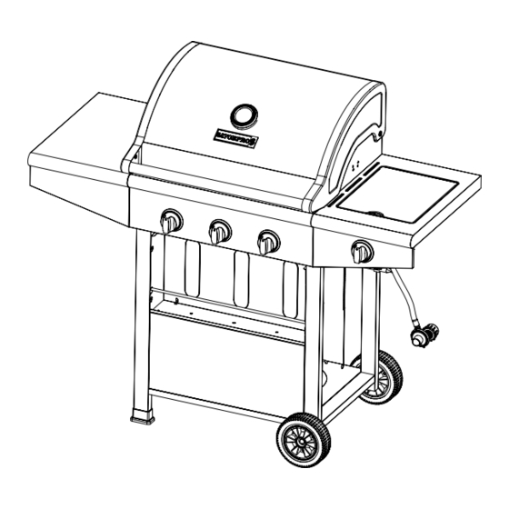
Page 5: Exploded View
EXPLODED VIEW... - Page 6 Gas cylinder saftey stop Wheel If you want to replace the parts, please feel free to contact us. We will be glad to assist you; please Refer to this model No.:GD4210S-B1 whenever you contact us. Thank you. GAE: Gas Appliance Experts P.
-
Page 7: Parts List
ASSEMBLY INSTRUCTIONS PLEASE READ THE INSTRUCTIONS CAREFULY AND FOLLOW STEP BY STEP. TOOLS REQUIRED: ■ Philips head screwdriver (not provided) ■ Adjustable / Allen wrench (not provided) ■ Soft Hammer(not provided) M6 Conical Washer... - Page 8 STEP 1: Insert the gas cylinder safety stop(15) to the related 2 holes into bottom panel(17) as shown, turn over the bottom panel, insert the R PIN in the 2 holes on gas cylinder safety stop. STEP 2: Install the cart left frame assembly(23) and cart right frame assembly(11) as pictures shown:...
- Page 9 STEP 3: Insert front panel of cart (19) to the 4 pre set screws in cart assembly as shown below. Install stay rod for condiment tray (20) into the pre drilled holes in left cart frame and right cart frame, then tighten all related screws. STEP 4: Insert condiment tray (14) into pre set screws as shown below, then tighten the related 4 screws.
- Page 10 STEP 5: Install cylinder stop rod (1) as shown, then insert 2 R pins in the 2 small holes at each end of rod STEP 6: Install plastic foot mats (22) as shown...
- Page 11 STEP 7: Install wheel axle (18) wheel (make sure the cone shaped side of center hub of wheel is facing cart) (16) wheel spacer (H) washer(C) lock nut M6 (D) as shown in sequence. STEP 8: Install drip tray left bracket (27) , match stick holder(12) and drip tray right bracket (10) as shown in sequence.
- Page 12 STEP 9: Install firebox assembly (02) as shown: STEP 10: Install left table front panel (29) and left table (30) as shown ①, then insert the left table assembly to the related hole pre set screws in side of firebox as shown ②, then tighten the related screws.
- Page 13 First, as shown in the direction①② remove side burner nut(06) STEP and side burner (05)Affix right table front panel (07) to right table (03) as shown in picture③, insert right table assembly to related holes as shown in picture④⑤, and tighten the related screws. STEP 12: Install knob bezel (08) and knob (09) per illustrations below.
- Page 14 STEP 13: Place the side burner (05) through the middle hole of right table assembly ( as shown below), make sure the valve tube threads through side burner support and settles so that the orfice is centered to tube. Then insert the igniter wire to side burner igniter as shown.
- Page 15 STEP 15: Install heat tent (26) as shown, pay attention that tabs at the end of the heat tent are inserted into stamped holes toward the front of the firebox. Install cast iron cooking grate(28) as pictured below STEP 16:...
- Page 16 STEP 17: Install warming rack (01). See below illustration: STEP 18: Install drip tray assembly (25) by sliding into drip pan brackets.
- Page 17 STEP 19: Install grease cup assembly (24) as pictured below: STEP 20: Install regulator hose plastic lock hoop (13) as picture idicates, then screw into the object carrier side.
- Page 18 STEP 21: Affix the gas cylinder safety stop over LP tank (15) according to the red arrowhead direction below.
-
Page 19: Gas Connection
GAS CONNECTION ONLY USE THE PRESSURE REGULATOR AND HOSE ASSEMBLY PROVIDED WITH THIS GRILL. REPLACEMENT PRESSURE REGULATORS AND HOSE ASSEMBLIES MUST BE SPECIFIED AS MODEL NO. 601-A MADE IN YUNG SHEN GAS APPLIANCE CO.,LTD OR MODEL NO. KR-106-01 MADE IN ZHONGSHAN KEYGAS GAS APPLIANCE CO., LTD This is a L.P. - Page 20 1. Make sure tank valve is in its full off position (turn clockwise to shut off). 2. Check tank valve to assure the threads are not damaged. (type I connection perANSIZ21.81) 3. Make sure all burner knobs are in the off position. 4.
-
Page 21: Leak Testing
To disconnect L.P. gas tank: 1. Turn all the knobs off. 2. Turn the tank valve off fully (turn clockwise to stop). 3. Detach the regulator assembly from tank valve by turning the quick coupling nut counterclockwise. 4. Place dust cap on the cylinder valve outlet whenever the cylinder is not in use. Only install the type of dust cap on the cylinder valve outlet that is provided with the cylinder valve. -
Page 22: Installer Final Check List
1. ALWAYS CHECK FOR LEAKS AFTER EVERY L.P. TANK CHANGE 2. ALWAYS CHECK FOR LEAKS OF EVERY CONNECTION BEFORE EACH USE. 3. USE LONG BBQ TOOL TO AVOID BURNS. 4. IF ANY GREASE OR HOT LIQUIDS ARE DRIPPING ONTO THE VALVE, OR REGULATOR HOSE, SHUT OFF THE GAS IMMEDIATELY. -
Page 23: Grill Lighting Instructions
GRILL LIGHTING INSTRUCTIONS WARNING: IMPORTANT! BEFORE LIGHTING: Carefully inspect the gas supply hose before turning the gas “ON”. If there is evidence of cuts, wear, or abrasion, it must be replaced before use. The replacement hose assembly shall be that specified in this manual. - Page 24 For safe operation ensure the gas valve assembly orifice is inside the burner tube before using your grill. See figure. If the orifices is not inside the burner tube, lighting the burner may cause explosion and/or fire resulting in serious bodily injury and/or property damage. FLAME CHARACTERISTICS: Check for proper burner flame characteristics.
-
Page 25: Operation Instructions
There is no unprotected combustible construction material over the grill. Do not obstruct the flow of combustion and ventilation air. OPERATION INSTRUCTIONS TOTAL GAS CONSUMPTION: Total gas consumption (per hour) of GD4210S-B1 grill with all burners on Main burners 36,000 Btu/hr Side burner 12,000 Btu/hr Total 48,000 Btu/hr... - Page 26 GENERAL USE OF THE GRILL: The grill burners encompass the entire cooking area and are side ported to minimize blockage from falling grease and debris. Above the burners are stainless steel radiated. The igniter knobs are located on the valve panel. Follow the lighting instructions printed on the control panel. USING THE GRILL: Grilling requires high heat for searing and proper browning.
-
Page 27: Care & Maintenance
Note: Should clean the grill after using them every time. Any questions please feel free to contact us. We will be glad to assist you; please refer to this model No.GD4210S-B1 whenever you contact us. Thank you. GAE: Gas Appliance Experts P. - Page 28 PRINTING. COOKING AREA CLEANING The easiest way to clean the grill is to clean immediately after turning off the flame and cooking is completed. Wear a barbeque mitt to protect your hand from the heat and steam. Dip a brass bristle barbeque brush in tap water and scrub the hot grill.
-
Page 29: Trouble Shooting
TROUBLE SHOOTING PROBLÈMES POSSIBLE CAUSE SOLUTIONS Electrode deposited Use clean swab and alcohol to clean with cooking residue Electrode damaged Replace Burner won't light after Electrode wires are loose or Reconnect or replace with new turning and pushing the knobs fall off electrode assembly with wires Orifice blocked... -
Page 30: Grilling Tips
GRILLING TIPS 1. The doneness of meat, whether rare, medium, or well done, is affected by the thickness to a large extent. 2. The cooking time is affected by the kind of meat, the size and shape of the cut, the temperature of the meat when cooking begins, and the degree of doneness desired.
Need help?
Do you have a question about the GD4210S-B1 and is the answer not in the manual?
Questions and answers