Table of Contents
Advertisement
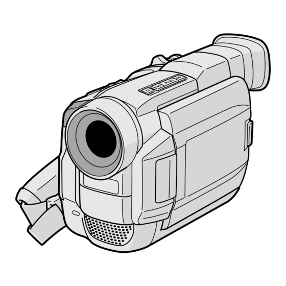
DIGITAL VIDEO CAMERA
GR-DVL105
Please visit our Homepage on the World Wide
Web and answer our Consumer Survey
(in English only):
http://www.jvc-victor.co.jp/english/index-e.html
INSTRUCTIONS
CONTENTS
Basic Recording ................................. 12
Advanced Features ............................ 19
Basic Playback .................................. 29
Advanced Features ............................ 30
Basic Connections .............................. 32
Advanced Connections ......................... 34
Dubbing To A VCR ............................. 36
Equipped With A DV Connector ............ 37
With A DV Connector ........................ 38
Playback and Playback Zoom .............. 41
Playback Special Effects ...................... 42
Random Assemble Editing .................... 43
For More Accurate Editing .................... 47
Audio Dubbing .................................. 49
Indications ...................................... 57
Controls, Connectors And Indicators ........ 60
LYT0626-001A
ENGLISH
6 - 11
12 - 28
29 - 35
36 - 38
39 - 49
50 - 56
57 - 61
62
63 - 65
66 - 67
68 - 69
EN
Advertisement
Chapters
Table of Contents

Related Manuals for JVC GR-DVL105


Summary of Contents for JVC GR-DVL105
-
Page 1: Table Of Contents
DIGITAL VIDEO CAMERA GR-DVL105 Please visit our Homepage on the World Wide Web and answer our Consumer Survey (in English only): http://www.jvc-victor.co.jp/english/index-e.html INSTRUCTIONS CONTENTS AUTOMATIC DEMONSTRATION 5 GETTING STARTED RECORDING 12 – 28 Basic Recording ... 12 Advanced Features ... 19 PLAYBACK 29 –... -
Page 2: Safety Precautions
If you notice smoke or a peculiar smell coming from the camcorder or AC adapter/charger, shut it down and unplug it immediately. Continue using the camcorder or AC adapter/charger under these conditions could lead to fire or electric shock. Contact your JVC dealer. Do not attempt to repair the malfunction yourself. - Page 3 When the equipment is installed in a cabinet or on a shelf, make sure that it has sufficient space on all sides to allow for ventilation (10 cm or more on both sides, on top and at the rear). Do not block the ventilation holes. (If the ventilation holes are blocked by a newspaper, or cloth etc.
-
Page 4: Provided Accessories
•AC Power Adapter/Charger AA-V40A/AS •Shoulder Strap •Audio/Video Cable (ø3.5 mini-plug to RCA plug) •Core Filter (for optional S-Video cable) PROVIDED ACCESSORIES •Remote Control Unit RM-V716U •AAA (R03) Battery x 2 (for remote control unit) •Editing Cable Both plugs have 1 ring around the pin. -
Page 5: Automatic Demonstration
How To Attach The Core Filter Attach the provided Core Filter to an optional S-Video cable, the PC connection cable provided with optional HS-V14KIT software. The Core Filter reduces interference. Stopper Release the Run the cable through the Core Filter, leaving approx. stoppers on both 3 cm of cable between the cable plug and the Core ends of the Core... -
Page 6: Getting Started
Battery pack BN-V408U, BN-V416U or BN-V428U POWER DC OUT connector indicator CHARGE indicator Battery pack Fully charging time BN-V408U approx. 1 hr. 30 min. BN-V416U (optional) approx. 2 hrs. BN-V428U (optional) approx. 3 hrs. 20 min. NOTES: If the protective cap is attached to the battery pack, remove it first. Perform charging where the temperature is between 10°C and 35°C. -
Page 7: Connectors
BATTERY RELEASE Button ATTENTION: Before detaching the power source, make sure that the camcorder’s power is turned off. Failure to do so can result in a camcorder malfunction. INFORMATION: VU-V856KIT is a set composed of the BN-V856U battery pack and AA-V80EG AC Power Adapter/Charger. -
Page 8: Controls
Power Zoom Lever Recording Start/Stop button PAUSE Grip Adjustment Power Switch Viewfinder Adjustment Dioptre Adjustment Control Shoulder Strap Attachment Tripod Mounting GETTING STARTED Separate the Velcro strip. Pass your right hand through the loop and grasp the grip. Adjust so that your thumb and fingers can easily operate the Recording Start/Stop Button and Power Zoom Lever. -
Page 9: Date/Time Settings
MENU/BRIGHT Wheel Power Switch Lock Button Power lamp Display – – – – – DISPLAY MENU Date/Time Settings The date/time is recorded onto the tape at all times, but its display can be turned on or off during playback pg. 30). Set the Power Switch to “... -
Page 10: Loading/Unloading Cassette
Erase protection tab* Cassette holder OPEN/EJECT Switch Cassette holder cover PUSH HERE * To Protect Valuable Recordings ..slide the erase protection tab on the back of the tape in the direction of “SAVE”. This prevents the tape from being recorded over. To record on this tape, slide the tab back to “REC”... -
Page 11: Recording Mode Setting
MENU/BRIGHT Wheel Power Switch Lock Button Power lamp Display Menu Screen Sub Menu Recording Mode Setting Set the tape recording mode depending on your preference. Set the Power Switch to “ the Lock Button located on the switch. The power lamp lights and the camcorder is turned on. -
Page 12: Recording
Power Switch Power lamp Recording Start/Stop Button Display 90 min 89 min (Now calculating) 0 min 1 min (Blinking) (Blinking) Tally lamp (lights while recording is in progress) BR I GHT – PUSH OPEN Button RECORDING NOTE: You should already have performed the procedures listed below. -
Page 13: Journalistic Shooting
(Manual) : Allows you to set various recording functions using the Menus. If you want more creative capabilities than Full Auto recording, try this mode. (Full Auto) : Allows you to record using NO special effects or manual adjustments. Suitable for standard recording. : Allows you to switch off the camcorder. - Page 14 Power Switch Lock Button SNAPSHOT Button MODE Button Display Snapshot mode FUL L RECORDING Basic Recording (cont.) Snapshot This feature lets you record still images that look like photographs onto a tape. SNAPSHOT MODE SELECTION Set the Power Switch to “ down the Lock Button located on the switch.
- Page 15 FRAME Snapshot mode with frame* FULL Snapshot mode with no frame* MULTI-4 Multi-Analyser 4 MULTI-9 Multi-Analyser 9 PIN-UP Pin-Up mode* * There is the sound effect of a shutter closing. NOTES: Even if “MULTI-4” or “MULTI-9” is engaged, Snapshot recording will be performed in the FULL mode during Digital Zoom.
- Page 16 Zoom in (T: Telephoto) 1 xW 1 0 xW 20xW Zoom out (W: Wide angle) Zoom display 1 0 xW Approximate zoom ratio Power Zoom Lever Power Switch RECORDING FEATURE: PURPOSE: To produce the zoom in/out effect, or an instantaneous 40xW change in image magnification.
- Page 17 NOTE: Recording From The Middle Of A Tape Time Code During recording, a time code is recorded on the tape. This code is to confirm the location of the recorded scene on the tape during playback. If recording starts from a blank portion, the time code begins counting from “00:00:00” (minute:second:frame).
- Page 18 30 cm between the video light and people or objects. Do not use near flammable or explosive materials. It is recommended that you consult your nearest JVC dealer for replacing the video light. RECORDING Basic Recording (cont.) Video Light...
-
Page 19: Advanced Features
RECORDING Advanced Features Focus detection zone Auto Focus FEATURE: PURPOSE: The camcorder’s Full Range AF system offers continuous shooting ability from close-up (as close as approx. 5 cm to the subject) to infinity. However, correct focus may not be obtainable in the situations listed below (in these cases use manual focusing): •When two subjects overlap in the same scene. - Page 20 MENU/BRIGHT Wheel Display – – – – – Sub Menu RECORDING Using Menus For Detailed Adjustment Power Switch This camcorder is equipped with an easy-to-use, on-screen menu system that simplifies many of the more Lock Button detailed camcorder settings ( Set the Power Switch to “...
- Page 21 Menu Screen Explanations Refer to “Fade/Wipe Effects” ( FADER/WIPE Refer to “Programme AE With Special Effects” ( P.AE/EFFECT Refer to “Exposure Control” and “Iris Lock” ( EXPOSURE Refer to “White Balance Adjustment” and “Manual White Balance Operation” W.BALANCE Allows you to set the recording mode (SP or LP) depending on your prefer- REC MODE ence ( Enables recording of stereo sound on four separate channels, and is recom-...
- Page 22 Menu Screen Explanations (cont.) DEMO. MODE TELE MACRO WIDE MODE CINEMA SQUEEZE : Factory-preset RECORDING Demonstrates certain functions such as Programme AE with special effects, etc., and can be used to confirm how these functions operate. When “DEMO. MODE” is set to “ON” and the Menu Screen is closed, demonstration starts. Performing any operation during the demonstration stops the demonstration temporarily.
- Page 23 Helps cut down on noise created by wind. “ WIND sound will change. This is normal. Disengages the function which cuts down on noise created by wind. Does not reset all settings to the factory-preset. CANCEL RESET EXECUTE Resets all settings to the factory-preset. Keeps the camcorder’s display (except the date, time and time code) from SCREEN appearing on the connected TV screen.
-
Page 24: Fade/Wipe Effects
Fade/Wipe Effects These effects let you make pro-style scene transitions. Use them to spice up the transition from one scene to the next. You can also vary transitions from scene to scene. IMPORTANT: Some Fade/Wipe Effects cannot be used with certain modes of Programme AE with special effects ( pg. - Page 25 Fader And Wipe Menu Menu FADER — WHITE FADER — BLACK FADER — MOSAIC FADER — B.W WIPE — CORNER WIPE — WINDOW WIPE — SLIDE WIPE — DOOR WIPE — SCROLL WIPE — SHUTTER DISSOLVE WIPE — CORNER WIPE — WINDOW WIPE —...
-
Page 26: Programme Ae With Special Effects
IMPORTANT: Some modes of Programme AE with special effects cannot be used with certain Fade/Wipe Effects ( pg. 25). If an unusable mode is selected, its indicator blinks or goes out. Display P. A 1/50 1/50 1/100 1/100 1/250 1/250 TWILIGHT Makes evening scenes look more natural. -
Page 27: Backlight Button
Exposure Control Manual exposure adjustment is recommended in the following situations: • When shooting using reverse lighting or when the background is too bright. • When shooting on a reflective natural background such as at the beach or when skiing. •... - Page 28 White Balance Adjustment A term that refers to the correctness of colour reproduction under various lighting. If the white balance is correct, all other colours will be accu- rately reproduced. The white balance is usually adjusted automatically. However, more advanced camcorder operators control this function manually to achieve a more professional colour/tint reproduction.
-
Page 29: Playback
PLAYBACK Basic Playback Play/Pause Button (4/6) Rewind Button (2) Fast-Forward Button Stop Button (5) Power Zoom Lever (VOL.) Speaker Lock Button Power Switch Still Playback: Pauses during playback. 1) Press 4/6 during playback. 2) To resume normal playback, press 4/6 again. If still playback continues for more than about 3 minutes, the camcorder’s Stop mode is automatically engaged. -
Page 30: Advanced Features
MENU/BRIGHT Wheel Recording Start/Stop Button Display * Each setting is linked with “DISPLAY MENU”, which appears when the Power Switch is set to “ ” ( pg. 23). The parameters are the same as in the description on pg. 23. NOTES: It is also possible to change the ON SCREEN settings by pressing DISPLAY on the remote... -
Page 31: Playback Sound
Playback Sound During playback, the camcorder detects the sound mode in which the recording was made, and plays the sound back. Select the type of sound to accompany your playback picture. According to the menu access explanation on pg. 30, select “SOUND MODE” or “12BIT MODE” from the Menu Screen and set it to the desired parameter. -
Page 32: Basic Connections
These are some basic types of connections. When making the connections, refer also to your VCR and TV instruction manuals. A. Connection to a TV or VCR equipped with an S-VIDEO IN and A/V input (RCA type) connectors Connector cover* * When connecting the cables, open this cover. - Page 33 Make sure all units are turned off. Connect the camcorder to a TV or VCR as shown in the illustration ( If using a VCR . . . go to step 3. If not . . . go to step 4. Connect the VCR output to the TV input, referring to your VCR’s instruction manual.
-
Page 34: Advanced Connections
Connector cover** To DV To PC IN/OUT (DIGITAL PHOTO) Core filter connection DV cable* cable (optional) To DV connector RS-232C PC with DV connector-equipped capture board * Use the DV cable provided with the capture board. ** When connecting the cable, open this cover. PLAYBACK Connection To A Personal Computer This camcorder can transfer still images to a PC by using... - Page 35 Also refer to the instruction manuals of the connected To PC connector units. When using a DV cable, be sure to use the optional JVC VC-VDV204U DV cable. Core filter connection cable (optional) To RS-232C pg.
-
Page 36: Dubbing
Connector To S cover** Audio/Video cable Core filter [mini-plug to RCA plug] (provided) S-Video cable (optional) VCR (Recording deck) * Connect when an S-Video cable is not used. ** When connecting the cables, open this cover. Dubbing To A VCR Following the illustration, connect the camcorder and the VCR. -
Page 37: Dubbing To A Video Unit Equipped With A Dv Connector
It is recommended to use the AC Power Adapter/ Charger as the power supply instead of the battery pack pg. 7). If the remote control is used when both the player and recorder are JVC video units, both units will perform the same operation. To prevent this from happening, press the buttons on both units. -
Page 38: Dubbing From A Video Unit Equipped With A Dv Connector
It is recommended to use the AC Power Adapter/Charger as the power supply instead of the battery pack pg. 7). If the remote control is used when both the player and recorder are JVC video units, both units will perform the same operation. To prevent this from happening, press the buttons on both units. -
Page 39: Using The Remote Control Unit
USING THE REMOTE CONTROL UNIT – Remote sensor Transmitted beam effective area The Full-Function Remote Control Unit can operate this camcorder from a distance as well as the basic operations (Playback, Stop, Pause, Fast-Forward and Rewind) of your VCR. It also makes additional playback functions possible. Installing The Batteries The remote control uses two “AAA (R03)”... - Page 40 USING THE REMOTE CONTROL UNIT Buttons Infrared beam transmitting window Zoom (T/W) Buttons DISPLAY Button SHIFT Button SLOW Rewind/Forward Buttons Left/Right Buttons REW Button FADE/WIPE Button EFFECT ON/OFF Button EFFECT Button PAUSE IN Connector START/STOP Button MBR SET Button SNAPSHOT Button Up Button INSERT Button* Down Button...
-
Page 41: Slow-Motion Playback, Frame-By-Frame Playback And Playback Zoom
Remote sensor Zoom Buttons SHIFT Left or SLOW Rewind Button Right or SLOW Forward Button Normal playback Press T To move image, press while keeping SHIFT held down. Playback Zoom FEATURE: PURPOSE: To magnify the recorded image up to 10X at any time during playback. OPERATION: 1) Press PLAY (4) to find the scene of interest. -
Page 42: Playback Special Effects
USING THE REMOTE CONTROL UNIT BACK Remote sensor PLAY EFFECT EFFECT ON/OFF PLAYBACK FEATURE: EFFECT Select Menu PURPOSE: To allow you to add creative effects to the playback image. OPERATION: 1) To start playback, press PLAY 2) Point the remote control at the camcorder's remote sensor and press EFFECT. -
Page 43: Random Assemble Editing
Editing. BUTTONS (A) (B) IMPORTANT Although the MBR is compatible with JVC VCRs and those of many other makers, it may not work with yours or may offer limited functions. NOTES: If the VCR’s power does not come on in step 1, try another code from the VCR CODE LIST. -
Page 44: Using The Remote Control Unit
** When connecting cables, open this cover. MAKE CONNECTIONS Also refer to pg. 32 and 33. A JVC VCR equipped with a remote pause connector . . . A JVC VCR not equipped with a remote pause connector but equipped with an To AV R.A.EDIT connector . - Page 45 Programme MODE Random Assemble – – – – – – Editing Menu – – – – Remote sensor FADE/WIPE EFFECT EDIT IN/OUT CANCEL NOTES: When choosing a scene, set Edit-In and Edit-Out points so that there is a relatively large difference between them.
-
Page 46: Automatic Editing To Vcr
USING THE REMOTE CONTROL UNIT Recording Start/Stop Button – – – – – – – – – – – – – – – – – – Remote Sensor FADE/WIPE EFFECT EDIT IN/OUT CANCEL AUTOMATIC EDITING TO VCR Rewind the tape in the camcorder to the beginning of the scene you want to edit and press PAUSE (6). -
Page 47: For More Accurate Editing
Programme 1 MODE Random Assemble – – – – – – Editing Menu – – – – (Recording deck) Remote sensor R.A.EDIT ON/OFF For More Accurate Editing Some VCRs make the transition from Record-Pause to Record mode faster than others. Even if you begin editing for the camcorder and the VCR at exactly the same time, you may lose scenes you wanted, or find that you have recorded scenes you did not want. - Page 48 USING THE REMOTE CONTROL UNIT MENU/BRIGHT Wheel Display 1 . 0 Remote sensor (Recording deck) R.A.EDIT ON/OFF ADJUSTMENT OF VCR/CAMCORDER TIMING Point the remote control at the camcorder’s remote sensor and press R.A.EDIT ON/OFF to make the Random Assemble Editing menu disappear, then press MENU/BRIGHT.
-
Page 49: Audio Dubbing
Display Audio Dub Standby mode Speaker Power Switch Remote sensor Stereo microphone A.DUB PLAY PAUSE STOP Audio Dubbing The audio track can be customized only when recorded in the 12-bit mode ( pg. 21). NOTES: Audio Dubbing is not possible on a tape recorded in 16-bit audio, on a tape recorded in the LP mode or on a blank portion of a tape. -
Page 50: Troubleshooting
If, after following the steps in the chart below, the problem still exists, please consult your nearest JVC dealer. The camcorder is a microcomputer-controlled device. External noise and interference (from a TV, a radio, etc.) might prevent it from functioning properly. In such cases, first disconnect its power supply unit (battery pack, AC Power Adapter/Battery Charger, etc.) and wait a few minutes;... - Page 51 SYMPTOM 8. Snapshot mode cannot be used. 9. The colour of Snapshot looks strange. 10. The image taken using Snapshot is too dark. 11. Digital Zoom does not work. 12. Programme AE with special effects and Fade/ Wipe Effects do not work. 13.
-
Page 52: "Off
SYMPTOM 15. The Picture Wipe and Dissolve functions do not work. 16. The picture wipe function does not work. 17. Scene transition does not go as expected. 18. The Video Echo mode does not work. TROUBLESHOOTING POSSIBLE CAUSES 15. •The last selected editing scene is ending. - Page 53 SYMPTOM 19. Even when Slow Shutter is not selected, the image looks like it is activated. 20. There is no strobe when the Classic Film or Strobe mode is activated. 21. White Balance cannot be activated. 22. When shooting a subject illuminated by bright light, vertical lines appear.
- Page 54 LCD monitor become dark. Consult your nearest JVC dealer. 27. •The light used to illuminate the LCD monitor causes it to become hot. 28. •This may occur when the surface or the edge of the LCD monitor is pressed.
-
Page 55: Viewfinder
SYMPTOM 31. During recording, sound cannot be heard. 32. Play, Rewind and Fast- Forward functions do not work. 33. The tape is moving, but there is no picture. 34. The LCD monitor image is distorted. 35. Images on the LCD monitor are jittery. - Page 56 If the indication remains even though you repeat the above two or three times, please consult your nearest JVC dealer. 40. •To protect the battery, it is recommended to charge it in places with a temperature of 10°C to 35°C ( pg.
-
Page 57: Index
INDEX Indications LCD Monitor/Viewfinder Indications During Recording & Displays the selected Fade/Wipe effect. Appears when in the Squeeze or Cinema mode. * Displays the recording mode (SP or LP). * Displays the tape remaining time. Appears during zooming. Zoom level indicator * •... -
Page 58: Warning Indications
LCD Monitor/Viewfinder Indications During Playback Warning Indications Indications CHECK TAPE’S ERASE PROTECTION SWITCH HEAD CLEANING REQUIRED USE CLEANING CASSETTE Displays the sound mode. Displays the tape speed. Appears while a tape is running. Displays the date/time. Displays the time code. •... - Page 59 Appears when the date/time is not set. Appears when the built-in clock battery runs out and the previously set date/time is erased. Consult your nearest JVC dealer for replacement. Appears for 5 seconds after power is turned on if the lens cap is attached.
-
Page 60: Controls, Connectors And Indicators
INDEX Controls, Connectors And Indicators 3 4 5 6 7 8 ^ & * (... -
Page 61: Video Light
Stud Hole ... Tripod Mounting Socket ... Random Assemble Editing. such as a personal computer. For further details, consult your nearest JVC dealer. are located beneath a cover. specification and extensions thereof. The is used for products compliant with the i.Link standard. -
Page 62: User Maintenance
After Use Turn off the camcorder. Slide and hold OPEN/EJECT in the direction of the arrow, then pull the cassette holder cover open until it locks. The cassette holder opens automatically. Remove the cassette. Press “PUSH HERE” to close the cassette holder. •Once the cassette holder is closed, it recedes automatically. -
Page 63: Cautions
Do not use near flammable or explosive materials. It is recommended that you consult your nearest JVC dealer for replacing the video light. General Battery Precautions If the remote control is not functioning even if it is being operated correctly, the batteries are ex- hausted. -
Page 64: Lcd Monitor
Also refer to the cleaning cassette’s instructions. If, after using the cleaning cassette, the problems still exist, consult your nearest JVC dealer. Mechanical moving parts used to move the video heads and video tape tend to become dirty and worn out over time. - Page 65 Serious malfunctioning If malfunctioning occurs, stop using the unit immediately and consult your local JVC dealer. The camcorder is a microcomputer-controlled device. External noise and interference (from a TV, a radio, etc.) might prevent it from function- ing properly.
-
Page 66: Terms
AC Power Adapter/Charger ... Audio Dubbing ... Auto Focus ... Auto Shut off ... Backlight Compensation ... Battery Low ... Battery Pack ... Brighten The LCD Monitor ... Channels (Left/Right) ... Charge The Battery Pack ... Cinema ... Classic Film ... Clean The Camcorder ... - Page 67 Picture Wipe/Dissolve ... Playback Special Effects ... Playback Zoom ... Power Switch Position ... Printer ... Programme AE With Special Effects ... Provided Accessories ... Random Assemble Editing ... Record-Standby ... Recording Mode ... Remote Control ... Reset ... Rewind The Tape ... Self-Recording ...
-
Page 68: Specifications
For General Power supply Power consumption LCD monitor off, viewfinder on LCD monitor on, viewfinder off Video light Dimensions (W x H x D) Weight Operating temperature Operating humidity Storage temperature Pickup Lens Filter diameter LCD monitor Viewfinder Speaker For Digital Video Camera Format Signal format Recording/Playback format... -
Page 69: Specifications
For Connectors Video output Audio output Input/output PC (DIGITAL PHOTO) Digital still output JLIP/EDIT AC Power Adapter/Charger AA-V40A/AS Power requirement Power consumption Output Charge Dimensions (W x H x D) Weight Specifications shown are for SP mode unless otherwise indicated. E & O.E. Design and specifications subject to change without notice. - Page 70 MEMO...
- Page 71 MEMO...
- Page 72 ®Registered Trademark owned by VICTOR COMPANY OF JAPAN, LTD. COPYRIGHT© 2000 VICTOR COMPANY OF JAPAN, LTD. VICTOR COMPANY OF JAPAN, LIMITED Printed in Japan 0500MKV...