Advertisement
Table of Contents
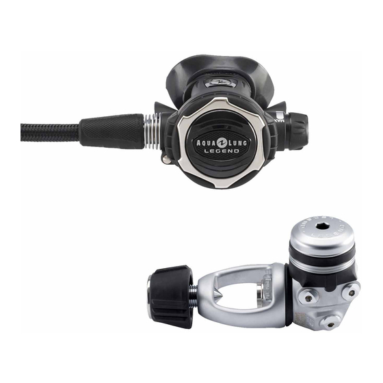
- 1 Second Stage
- 2 Table of Contents
- 3 Copyright
- 4 Introduction
- 5 Warnings, Attention, Note
- 6 Maintenance
- 7 General Instructions
- 8 General Conventions
- 9 Disassembly Procedure
- 10 Reassembly Procedure
- 11 Table 1. Troubleshooting Guide
- 12 Table 2. List of Tools and Service Kits
- 13 Table 3. Recommended Cleaners and Lubricants
- 14 Procedure A. Cleaning and Lubricating
- 15 Table 5. Checking Specifications
- 16 Exploded View of Legend Second Stage
- Download this manual
Advertisement
Table of Contents

Related Manuals for Aqua Lung LX Supreme


Summary of Contents for Aqua Lung LX Supreme
-
Page 1: Second Stage
SERVICE MANUAL SECOND STAGE LX and LEGEND Copyright ©2005 Aqualung France Rev. 02/2005... -
Page 2: Table Of Contents
Index COPYRIGHT..........................3 INTRODUCTION........................3 WARNINGS, ATTENTION, NOTE...……………................ 3 MAINTENANCE.......................... 3 GENERAL INSTRUCTIONS.....……................3 GENERAL CONVENTIONS…....................4 DISASSEMBLY PROCEDURE…....................4 REASSEMBLY PROCEDURE..…...................7 SECOND STAGE ADJUSTMENT........…............9 FINAL ASSEMBLY.............…..........…..10 Table 1. Troubleshooting guide..........…......…....11 Table 2. List of tools and service kits..........………......……..12 Table 3. Recommended cleaners and lubricants...............…..13 Procedure A. -
Page 3: Copyright
Keep this manual open near to you so that you can refer to it step ©2005 Aqua Lung France. by step. Do not rely on your memory.. INTRODUCTION... -
Page 4: Disassembly Procedure
from the hose nipple. Take care not to damage the O- The acronyms used: ring groove. Remove the O-ring from the hose threaded LP: Low Pressure end. MP: Medium Pressure HP: High Pressure Numbers in brackets indicate the part number of the component shown on the exploded view attached. - Page 5 F I R S T D I V E Turn the adjustment handwheel anti-clockwise to the 11. Insert a rod or tool (116236) into the insert (threaded end. Hold the lever (8) down against the insert (7) and side) and push out the valve seat assembly. Separate pull on the handwheel to remove the insert assembly the components of the valve seat.
-
Page 6: Reassembly Procedure
16. If the regulator is a Legend LX Supreme, remove the lip shield (36). Remove the mouthpiece collar (29) then the mouthpiece (17). Fit a new lubricated O-ring (20) into the shuttle valve throat (12). - Page 7 F I R S T D I V E Insert the assembled shuttle valve, notch downwards, 10. Fit a new lubricated O-ring (24) onto the venturi control into the insert, holding the lever at right angles to the (6). Position the control handle upwards and push it fully insert.
- Page 8 14. With the flat side of the casing at eye level, screw in the Fit the diaphragm (13) in the casing. Press all around adjusting knob until the lever is about 4mm below the the edges with a finger to ensure that it is in place. Fit level of the casing edge.
- Page 9 F I R S T D I V E m.kg FINAL CHECKS Note : If you have a regulator Test Bench, carry out these test before refitting the mouthpiece. 1. Put the regulator under pressure with a 200 bar (±10 Instructions for the check are given in the bar) supply.
-
Page 10: Table 1. Troubleshooting Guide
Table 1. Troubleshooting Guide SYMPTOM POSSIBLE CAUSE TREATMENT 1. Refer to First stage Troubleshooting 1. MP too high Guide 2. The valve (18) is worn or damaged. 2. Replace the valve 3. The seat (9) is not correctly adjusted 3. Readjust the seat Leak or free flow at 2 stage 4. -
Page 11: Table 2. List Of Tools And Service Kits
F I R S T D I V E Table 2. List of Tools and Service Kits DESCRIPTION APPLICATION PART 116222 MP pressure gauge complete 0/16B Checking medium pressure 111610 O-ring tool Fitting and removing O-rings 944022 129001 Spring clip tool Fitting and removing diaphragm clip (15) 129001 116236... -
Page 12: Table 3. Recommended Cleaners And Lubricants
Table 3. Recommended cleaners and lubricants LUBRICANT / CLEANER APPLICATION SOURCE Cristo-Lube MCG 111 All O-rings Aqualung, ref. 480025 Attention: Silicone parts do not require lubrication. Do not grease them. Greasing silicone parts can change their molecular construction and cause premature degradation of the material. Oakite #31 Acid bath for cleaning brass and stainless Oakite Products, Inc. -
Page 13: Procedure A. Cleaning And Lubricating
F I R S T D I V E Procedure A Cleaning and Lubricating (All Aqualung Regulators) Cleaning brass and stainless steel parts. Pre-clean by soaking in NETALU diluted to 25%. Cleaning in an ultra-sonic bath filled with a mixture of washing-up liquid + hot water. If some resistant deposits remain then fill the ultrasonic bath with white vinegar and repeat. -
Page 14: Table 5. Checking Specifications
Table 4. Torque values N° REFERENCE DESCRIPTION FORCE AP2031 Nut (5) 0.5 m.kg. Table 5. Checking specifications TEST INSTRUCTIONS SPECIFICATIONS Leak Test 160 bar < Working pressure < 200 bar No leak MP at 9.5 bar ± 0.5 bar: Legend and Titan LX Medium Pressure 160 bar <... - Page 15 F I R S T D I V E Maintenance Notes.
-
Page 16: Exploded View Of Legend Second Stage
Exploded view of Legend second stage. Exploded view of Legend Supreme second stage. - Page 17 F I R S T D I V E...
- Page 18 Exploded view of LX second stage.
- Page 19 F I R S T D I V E Exploded view of LX Supreme second stage.
- Page 20 Exploded view of Octopus LX second stage.
- Page 21 F I R S T D I V E Exploded view of Octopus Legend second stage.
- Page 22 1ere Avenue – 14 rue – BP 148 06513 CARROS cedex – France 00 33.(0)4 92 08 28 88 FAX 00 33.(0)4 92 08 28 99...
Need help?
Do you have a question about the LX Supreme and is the answer not in the manual?
Questions and answers