Table of Contents
Advertisement
Advertisement
Table of Contents

Related Manuals for Interlogix TVF-1101


Summary of Contents for Interlogix TVF-1101
-
Page 1: Camera Installation
TruVision 360° Camera Installation Manual P/N 1072845A-EN • REV 1.0 • ISS 25SEP14... - Page 2 © 2014 United Technologies Corporation, Copyright Interlogix is part of UTC Building & Industrial Systems, a unit of United Technologies Corporation. All rights reserved. Trade names used in this document may be trademarks or registered trademarks Trademarks and of the manufacturers or vendors of the respective products.
-
Page 3: Table Of Contents
Mounting accessories 9 Network settings 10 Using the web browser to configure 11 Using the camera with an Interlogix NVR or another system 13 Using the camera with TruVision Navigator 13 Specifications 13 Pin definitions 14... -
Page 4: Introduction
Product overview This is the user manual for TruVision 360° camera models: Description TVF-1101 TruVision 360 Degree IP Dome, 3.0 MPX, WDR, 1.19mm fisheye lens, true D/N, 10m IR, 2 way audio (built-in mic & speaker), SD/SHDC slot, POE (803.af) /12VDC, PAL. -
Page 5: Installation
Installation This chapter provides information on how to install the cameras. Installation environment When installing your product, consider these factors: • Electrical: Install electrical wiring carefully. It should be done by qualified service personnel. Always use a proper PoE switch or a 12 VDC UL listed Class 2 or CE certified power supply to power the camera. -
Page 6: Cable Requirements
Hex wrench 95 x 50 mm Screws: Drywall anchor Φ7.5 x 24.5mm (3 pcs) Screw M4 16 x 25mm (3 pcs) Drill template (170 x 170 mm) Installation manual CD (Includes Configuration Manual, Water joint (Provides water Installation Manual, TruVision Device resistance to network connection) Finder and Adobe Reader 12 VDC Connector:... -
Page 7: Camera Description
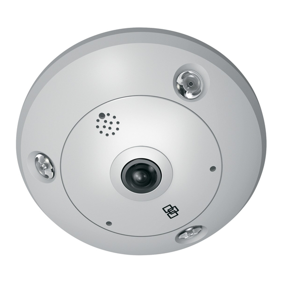
The recommended power cable requirements to use are a 12 VDC power jack or PoE (802.3af) when connecting the camera. Camera description Figure 1: 360° camera 1. Base 6. Mic in 2. Micro SD card slot 7. Camera cover ring 3. -
Page 8: Install The Camera
Install the camera Note: If the light source where the camera is installed experiences rapid, wide- variations in lighting, the camera may not operate as intended. To install the 360° camera on a ceiling or wall: Prepare the mounting surface. Use the drill template provided to draw the positions of the screws and cabling hole. - Page 9 Grasp the opening on the side of the cover, and pull the cover and base apart to open the camera (3). Note: For further information on removing the cover ring from the camera, please refer to the guide, “Instructions to remove the 360° camera cover”. Connect the cables to the camera.
-
Page 10: Ir Illuminators
Tighten the cover screw (1) in the camera cover ring to securely reattach cover to the camera. IR illuminators The camera’s built-in IR illumination provides high-quality video in low-light environments, even when there is no other illumination available. You can configure the IR illumination using a web browser or a client software. If the function is enabled, the IR light is On when the camera enters night (black and white) mode. -
Page 11: Mounting Accessories
Figure 2: Access the micro SD card in the camera Video and log files stored on the micro SD card can only be accessed via the web browser. You cannot access the card using TruVision Navigator or a recording device. Mounting accessories Brackets and back boxes described below are available for other installation scenarios. -
Page 12: Network Settings
Round angled back box Example: Round angled back box with camera TruVision 360° camera cup base (TVF-CBM) The 360° camera can be installed on a cup base then attached to a TruVision swan neck bracket (TVD-SNB) for wall mounting, or to a TruVision pendant (TVD-PPB) for ceiling mounting. -
Page 13: Using The Web Browser To Configure
Browse to the folder IP Discovery Tools and double-click the Setup file located in the folder. Following the instructions, select the folder where setup will install the files then click Next. The program requires a utility called WinPcap to be installed on the computer. - Page 14 Figure 3: Live view interface Table 1: Overview of the Live View interface Name Description Live View Click to view live video. Playback Click to playback video. Click to search for event logs. There are three main types: Alarm, Exception, and Operation. Configuration Click to display the configuration window for setting up the camera.
-
Page 15: Using The Camera With An Interlogix Nvr Or Another System
Using the camera with TruVision Navigator A camera must be connected to an Interlogix NVR in order to be operated by TruVision Navigator. Please refer to the TruVision Navigator user manual for instructions on operating the camera with the TruVision Navigator. -
Page 16: Pin Definitions
Outdoor camera dimensions: Indoor camera dimensions: Pin definitions There are eight wires on a standard UTP/STP cable and each wire is color- coded. The following shows the pin allocation and color of straight and crossover cable connection: Figure 4: Straight-through cable White/Orange White/Orange Orange...
Need help?
Do you have a question about the TVF-1101 and is the answer not in the manual?
Questions and answers