Spektrum DX8 Instruction Manual
8-channel dsm radio system with integrated telemetry for airplanes and helicopters
Hide thumbs
Also See for DX8:
- Instruction manual (208 pages) ,
- Setup (7 pages) ,
- Instruction manual (28 pages)
Table of Contents
Advertisement
Quick Links
Advertisement
Table of Contents

Related Manuals for Spektrum DX8


Summary of Contents for Spektrum DX8
- Page 1 Инструкция для Spektrum DX8i Перейти в карточку товара 8 800 775 98 98...
- Page 2 The Leader in Spread Spectrum Technology Instruction Manual Bedienungsanleitung Manuel d’utilisation Manuale di istruzioni Manual de Instrucciones SD Logo is a trademark of SD-3C, LLC...
- Page 4 Instruction Manual The Leader in Spread Spectrum Technology 8-Channel DSM Radio System with Integrated Telemetry for Airplanes and Helicopters SD Logo is a trademark of SD-3C, LLC...
- Page 5 Thank You for purchasing a genuine Spektrum Product. Always purchase products from a Horizon Hobby, Inc. authorized dealer to ensure authentic high-quality Spektrum product. Horizon Hobby, Inc. disclaims all support and warranty with regards, but not limited to, compatibility and performance of counterfeit products or products claiming compatibility with DSM2 or Spektrum.
-
Page 6: Table Of Contents
Spektrum’ s DX8 with Integrated Telemetry ............6 Troubleshooting Guide ...................35 Included Items ....................6 General Information ..................36 System Features ....................6 Servo Precautions Charging Your Transmitter ................7 General Notes NiMH/LiPo Battery Support ................7 Safety Do’ s and Don’ts for Pilots Battery and Charging Precautions and Warnings ..........7 Federal Aviation Administration..............36... - Page 7 The receivers. DX8 is SD-card compatible allowing an infinite number of models to be stored and transferred. Plus firmware updates can be downloaded from the When using the DX8 with parkflyer receivers (the SPEKTRUMRC.com website providing the user with the latest software upgrades.
- Page 8 NEXT at the bottom right of the System setting screen. The following Never plug in a peak detection or fast charger into your screen appears. DX8 as this could damage the internal charge circuit. Use only a 12V DC source. Rotate the roller to highlight battery type.
- Page 9 Note: to change transmitter modes see page 39 Do not attempt to use the antenna to bear any weight, pick up the transmitter by the antenna or alter the antenna in any way. If the transmitter antenna or related components become damaged the output strength can be severely impeded which could lead to a crash, injury, and property damage.
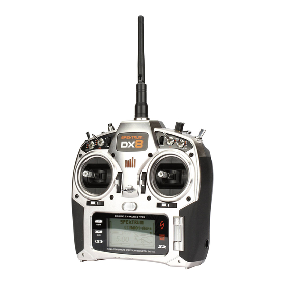
- Page 10 Antenna Aux 3 Knob Handle Trainer/Timer R Trimmer Aux 2/Governor Bind Button Gear L Trimmer Mix/Hold Flap/Gyro Flight Mode Elevator D/R Aileron D/R Elevator/Rudder Stick Throttle/Aileron Stick Rudder Trim Aileron Trim Throttle Trim SD Card Slot Charge Jack Elevator Trim Rolling Selector Clear Button Back Button...
-
Page 11: Digital Trims
The DX8 utilizes a roller that can be rotated or pressed and two buttons, Back and The DX8 features a No RF output warning. If the 2.4GHz band is full, it’ s possible Clear that are used to access and program all the functions. -
Page 12: Binding
It is recommended to use one of the carbon fuselage receivers. (SPMAR9300, Do not use amplified Y-harnesses and servo extensions with Spektrum SPMAR6255). equipment. Only use standard non-amplified Y-harnesses and servo extensions. -
Page 13: Failsafe
-SmartSafe sets the throttle to the position it was in during the binding process. SmartSafe is automatically set when hold last command failsafe or Preset failsafe is programmed or the system is bound. Note: It’ s important to have the throttle Note: To bind an aircraft with an electronic speed controller that powers stick in the low position to store low throttle during binding the receiver through the throttle channel (ESC/BEC), insert the bind plug... -
Page 14: Range Testing
Press and hold the roller while turning on the transmitter. When System Setup Range Testing the DX8 appears on the screen, release the roller. The DX8 is now in System Setup Mode. 1. With the model restrained on the ground, stand 30 paces (approx. -
Page 15: Model Select
Model Type programs the selected model memory to function in Helicopter or when switching from the current model. You can store up to 30 models in the DX8’ s Airplane programming. You should program Model Type first when setting up a model memory. -
Page 16: Model Name
Press and hold the roller while turning on the transmitter. When System Setup roller to the desired wing mix. Press the roller to select. appears on the screen, release the roller. The DX8 is now in System Setup Mode. Rotate the roller to highlight Model Name then press to access the function. -
Page 17: F-Mode Setup
Press and hold the roller while turning on the transmitter. When System Setup appears on the screen, release the roller. The DX8 is now in System Setup Mode. Select the channel or function you wish to assign. See chart for options. Press the roller to accept. -
Page 18: Model Reset
Press and hold the roller while turning on the transmitter. When System Setup appears on the screen, release the roller. The DX8 is now in System Setup Mode. Verify that the model displayed on this screen is the model you wish to reset. If Rotate the roller to highlight Trim Setup then press to access the function. -
Page 19: Warnings
Data port to the Data port on the telemetry appears on the screen, release the roller. The DX8 is now in System Setup Mode. module. You can use servo tape to secure the TM1000 module or wrap it in foam with the receiver. - Page 20 5. From the main screen rotate the roller to access the telemetry screen and verify the flight log data and receiver voltage displays. The TM1000 includes a temperature and external voltage sensors. Optional RPM sensors are available for Gas/Glow and electric brushless models to monitor RPM. Two RPM sensors are available: SPMA9569 for nitro and gas engines, Temperature Sensor SPMA9558 for brushless electric motors.
-
Page 21: Frame Rate
The following screen appears: Press and hold the roller while turning on the transmitter. When System Setup appears on the screen, release the roller. The DX8 is now in System Setup Mode. Highlight System Settings then press. The following screen appears: Rotate the roller to highlight the frame rate then press. -
Page 22: Transfer Sd Card
Press and hold the roller while turning on the transmitter. When System on the lower left of the startup screen. Setup appears on the screen, release the roller. The DX8 is now in System Setup Mode. In the Systems Settings screen rotate the roller to highlight User Contrast then press. -
Page 23: Servo Setup
Highlight the channel then press the roller. Rotate the roller to access the channel you wish to adjust then press to accept. The DX8 organizes the programming screens in two separate categories: System Setup Mode and Functions Mode. Function Mode programming adjusts a model’... - Page 24 Highlight the Speed value at the bottom of the screen and press the roller to With the transmitter on and the main or telemetry screen up, press the roller. access. With the Speed value highlighted rotate the roller to adjust the servo speed for the selected channel.
-
Page 25: Differential
Rotate the roller to highlight Sw (switch) then press to access the switch options. With the transmitter on and the main or telemetry screen displayed, press the Select the desired switch to change the dual rate for that channel or inhibit then roller. -
Page 26: Throttle Cut
With the transmitter on and the main or telemetry screen displayed, press the roller. The Function list displays. The Throttle Cut function allows you to shut off an engine with the Trainer switch, Gear switch or the Right or Left trimmer. When you activate the programmed switch, the throttle channel is driven to it’... -
Page 27: Flap System
The DX8 features a 5-point throttle curve. You can assign up to four separate throttle curves. A graph displays at the left side of the screen to aid in adjusting throttle curves. -
Page 28: Swashplate
Rotate the roller to highlight Flap System then press. channels. Do this so that when an aileron input on the transmitter’ s stick tilts the swashplate right and left, an elevator input tilts the swashplate fore and aft, and a pitch input raises and lowers the swashplate. -
Page 29: Governor
.5% increments to allow for precise rpm adjustments. Also, you can program the channel the governor controls. The DX8 features a 5-point Pitch curve. You can set up to four separate Pitch curves. A graph displays at the left side of the screen to aid in adjusting pitch curves. -
Page 30: Aileron To Rudder Mix
Move the aileron stick The DX8 offers eight mixes in airplane model type. There is an Elevator to Flap in position to highlight the desired rates then rotate the roller to adjust the value. - Page 31 With the Elevator to Flap mix screen displayed, rotate the roller to highlight Ele > Flp then press the roller. Now rotate the roller to select programmable Mix, 1, 2, 3, 4, 5, or 6 and press the roller. The Mix screen appears. The offset function establishes the point at which the two mix rates converge.
- Page 32 The throttle position should increase. If it decreases then the opposite value (positive vs. negative) is needed. The DX8 offers eight mixes in helicopter model type. You can program a cyclic- to-throttle mix to advance the throttle when aileron, elevator and or rudder inputs...
- Page 33 press the roller. Select programmable Mix, 1, 2, 3, 4, 5, or 6 and press the roller. The Swashplate Mix typically corrects swashplate timing issues by mixing Aileron The Mix screen appears. to Elevator and Elevator to Aileron. When adjusted correctly, the Swashplate causes the helicopter to roll and pitch accurately with minimal inter-reaction.
-
Page 34: Gyro
Also, you can program the channel the gyro gain is controlling. The DX8 displays gyro gain values as N for Normal gain and a T for tail lock (heading hold). The percentage values are the true gain values in each The DX8 Timer function allows you to program a Count Down timer or Stop mode. - Page 35 Rotate the roller to highlight Start then press to access. Five start options are available: Trainer switch, Throttle, Throttle 1-Time, L Trim and R Trim. Throttle 1-time - The timer starts when the programmed throttle position is exceeded and will continue regardless of the throttle position. Throttle - The timer starts when the programmed throttle position is exceeded.
-
Page 36: Monitor
Rotate the roller to highlight Monitor then press to access. The Monitor screen displays the servo positions for each channel graphically and numerically. This is useful to verify programming functions, trim settings, mix directions, etc. The numeric value is directly relative to the travel adjust and mix values (e.g., 100% travel adjust equals 100% value in the Monitor). -
Page 37: General Notes
Flight Checks Section” for information. Servo Precautions could result in injury to people or damage of property. sure they are able to travel their full deflection. Overloading or stalling a servo can disorientation and loss of control of your aircraft. Strong winds can cause similar cause excessive current drain. -
Page 38: Warranty And Repair Policy
WARRANTY AND REPAIR POLICY HORIZON SHALL NOT BE LIABLE FOR SPECIAL, Warranty Period INDIRECT OR CONSEQUENTIAL DAMAGES, LOSS Exclusive Warranty- Horizon Hobby, Inc., (Horizon) OF PROFITS OR PRODUCTION OR COMMERCIAL warranties that the Products purchased (the “Product”) LOSS IN ANY WAY CONNECTED WITH THE PRODUCT, will be free from defects in materials and workmanship WHETHER SUCH CLAIM IS BASED IN CONTRACT, for 1 year from the date of purchase by the Purchaser. -
Page 39: Included Items
Provided warranty conditions have been When operating your Spektrum transmitter, please be sure to maintain a met, your Product will be repaired or replaced free of separation distance of at least 5 cm between your body (excluding fingers, hands, wrists, ankles and feet) and the antenna to meet RF exposure safety charge. -
Page 40: Declaration Of Conformity
The following information is for item numbers: SPM8800EU The DX8 can be easily converted to mode 1, 2, 3, or 4. This conversion requires a mechanical and a programming change. (Stick and switch positions for mode 1 and 2 are illustrated on pages 8 and 9.) Following are detailed instructions on... - Page 41 Press and hold the roller while turning on the transmitter. When System Setup appears on the screen, release the roller. The DX8 is now in System Setup Mode. Highlight System Settings then press the roller to access the System Settings function.
- Page 42 Telemetry module, make sure it’ s bound to the receiver. 2. Advance the Flight Log until F- frame losses are displayed, by pressing the button on the flight log. Or advance the screen on the DX8 to show the flight log telemetry.
- Page 43 The Flight Log (optional) is compatible with the AR8000 receiver. The Flight Log displays overall RF link performance as well as the individual internal and external receiver link data. It also displays receiver voltage. After a flight and before turning off the receiver or transmitter, plug the Flight Log into the Data port on the AR8000 receiver.
- Page 44 Spektrum DX8i Описание Характеристики...
Need help?
Do you have a question about the DX8 and is the answer not in the manual?
Questions and answers