Table of Contents
Advertisement
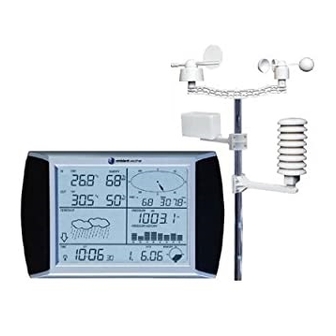
Ambient Weather WS-1090 Wireless Home Weather
Table of Contents
1.
Introduction ..................................................................................................................................... 2
2.
Warnings and Cautions.................................................................................................................... 2
3.
Getting Started ................................................................................................................................ 2
3.1
Parts List ................................................................................................................................. 2
3.2
Recommend Tools .................................................................................................................. 3
3.3
Sensor Assembly Set Up ........................................................................................................ 3
3.4
Display Console ..................................................................................................................... 9
3.4.1
Display Console Layout ..................................................................................................... 9
3.4.1
Initial Display Console Set Up ......................................................................................... 10
3.4.2
Radio Controlled Clock (RCC) ........................................................................................ 11
3.4.3
Sensor Operation Verification .......................................................................................... 11
4.
Weather Station Installation .......................................................................................................... 11
4.1
Pre Installation Checkout ..................................................................................................... 11
4.2
Site Survey ........................................................................................................................... 11
4.3
Final Installation of Sensor Array......................................................................................... 12
5.
Console Operation ......................................................................................................................... 12
5.1
Indoor Temperature .............................................................................................................. 12
5.2
Outdoor Temperature, Wind Chill and Dew Point ............................................................... 13
5.3
Indoor Humidity ................................................................................................................... 14
5.4
Outdoor Humidity ................................................................................................................ 15
5.5
Wind Speed .......................................................................................................................... 16
5.6
Rain ...................................................................................................................................... 16
5.7
Weather Forecast (Tendency) ............................................................................................... 17
5.8
Barometric Pressure ............................................................................................................. 18
5.9
Pressure Graph ..................................................................................................................... 20
5.10
Time ..................................................................................................................................... 20
5.11
Date ...................................................................................................................................... 21
5.12
Memory ................................................................................................................................ 22
6.
PC Software .................................................................................................................................. 23
6.1
EasyWeather Overview ........................................................................................................ 23
6.2
Connect PC Connection ....................................................................................................... 24
6.3
EasyWeather Software Installation ....................................................................................... 24
6.4
Run EasyWeather ................................................................................................................. 24
6.5
EasyWeather Features .......................................................................................................... 24
6.5.1
Main Display .................................................................................................................... 24
6.5.2
Set-up and Alarms ............................................................................................................ 25
6.5.3
Alarm Values .................................................................................................................... 26
6.5.4
Historical Highs and Lows ............................................................................................... 27
6.5.5
Historical Data ................................................................................................................. 28
6.5.6
Graph Data ....................................................................................................................... 29
6.5.7
EasyWeather Legal Notes ................................................................................................ 30
7.
Glossary of Terms ......................................................................................................................... 30
Version 1.1
Station User Manual
©Copyright 2010, Ambient LLC. All Rights Reserved.
Page 1
Advertisement
Table of Contents

Related Manuals for Ambient Weather WS-1090


Summary of Contents for Ambient Weather WS-1090
-
Page 1: Table Of Contents
Ambient Weather WS-1090 Wireless Home Weather Station User Manual Table of Contents Introduction ............................. 2 Warnings and Cautions........................2 Getting Started ..........................2 Parts List ..........................2 Recommend Tools ........................3 Sensor Assembly Set Up ......................3 Display Console ........................9 3.4.1... -
Page 2: Introduction
Warranty Information ....................... 36 1. Introduction Thank you for your purchase of the Ambient Weather WS-1090 wireless weather station. The following user guide provides step by step instructions for installation, operation and troubleshooting. To download the latest manual and additional troubleshooting tips, please visit: http://ambientweather.wikispaces.com/ws1080... -
Page 3: Recommend Tools
Rain gauge mounting bracket USB cable (L: 41”) Easy Weather CD 1” nuts and bolts (long) 13/16” bolt (short) ½” set screw (long) 3/8”set screw (short) (Optional) Upper pole (L: 12”) Lower pole (L: 12”) Zip ties Hose clamps (2 ¾” diameter) 3.2 Recommend Tools ... - Page 4 holes, and fasten with long bolt and nut. Tighten with precision screwdriver while securing the nut with pliers, as shown in Figure 2. Figure 2 Version 1.1 ©Copyright 2010, Ambient LLC. All Rights Reserved. Page 4...
- Page 5 3. Connect the anemometer assembly to the top mounting pole, align the holes, and fasten with short set screw (optional) and long bolt and nut. Tighten with precision screwdriver while securing the nut with pliers, as shown in Figure 3. Note: This may be a tight fit –...
- Page 6 Figure 4 Version 1.1 ©Copyright 2010, Ambient LLC. All Rights Reserved. Page 6...
- Page 7 5. Connect the thermo-hygrometer with short bolt and nut. Tighten with precision screwdriver, as shown in Figure 5. Slide the radiation shield over the thermo-hygrometer after connecting the cables from the anemometer and rain gauge (step 7). Attach to the thermo-hygrometer mounting arm to the upper mounting pole.
- Page 8 Figure 6 Connect the wind speed cable to the wind direction phone jack, as shown in Figure 7. Connect the wind direction cable to the thermo-hygrometer phone jack (reference the label on the thermo-hygrometer). Connect the rain gauge cable to the thermo-hygrometer phone jack (reference the label on the thermo-hygrometer).
-
Page 9: Display Console
Figure 7 3.4 Display Console 3.4.1 Display Console Layout Note: All display console touch screen commands are issued by touching (not pressing) the related areas as shown in Figure 8. Pressing hard on the display console may damage the unit. The touch screen LCD monitor is laid out as follows: Left Top LCD: IN-OUT temperature and humidity... -
Page 10: Initial Display Console Set Up
Figure 8 3.4.1 Initial Display Console Set Up Note: The sensor array must be powered and updating before powering up the console, or the console will give up searching for the sensors. Perform this step last. Make certain the weather station sensor array is at least 10’ away from the console and within 300’ of the console. -
Page 11: Radio Controlled Clock (Rcc)
the tendency section of the display to increase, set or decrease values. Every time you touch the screen, the backlight will light up and a beep will sound. After 30 seconds of inactivity, the LCD will automatically revert to the normal display mode (automatic time out). 3.4.2 Radio Controlled Clock (RCC) After the remote sensor is powered up, the sensor will transmit weather data for 30 seconds, and then the sensor will begin radio controlled clock (RCC) reception. -
Page 12: Final Installation Of Sensor Array
5. Radio interference such as PCs, radios or TV sets can, in the worst case, entirely cut off radio communication. Please take this into consideration when choosing console or mounting locations. 6. Visit Ambient Weather Mounting Solutions for assistance and ideas for mounting your weather station: http://www.ambientweather.com/amwemoso.html 4.3 Final Installation of Sensor Array... -
Page 13: Outdoor Temperature, Wind Chill And Dew Point
+ button and – button will be flashing (in the tendency section of the flashing and the display). Indoor Temperature Units. Touch the + button or – button to alternate the display unit between ℃ and ℉ (press the indoor temperature again if you wish to skip this setting). Indoor Temperature High Alarm. -
Page 14: Indoor Humidity
1. Touch the outdoor temperature once, as shown in Figure 10. The outdoor temperature will + button and – button will be flashing (in the tendency section of the begin flashing and the display). Outdoor Temperature, Wind chill and Dew Point. Touch the + button or – button to alternate the display between the outdoor temperature, wind chill and dew point. -
Page 15: Outdoor Humidity
Figure 11 1. Touch the indoor humidity once, as shown in Figure 11. The indoor humidity will begin + button and – button will be flashing (in the tendency section of the flashing and the display). Indoor Humidity High Alarm. Touch the INDOOR HUMIDITY section again to set the indoor humidity high alarm function. -
Page 16: Wind Speed
5.5 Wind Speed Figure 12 1. Touch the wind speed once, as shown in Figure 10. The wind speed will begin flashing and + button and – button will be flashing (in the tendency section of the display). Average Wind Speed and Wind Gust. Touch the + button or – button to alternate the display between the three minute Wind Average Speed and Gust Speed (and the maximum wind speed in the update period). -
Page 17: Weather Forecast (Tendency)
Figure 13 1. Touch the rain once, as shown in Figure 13. The rain will begin flashing and the + button and – button will be flashing (in the tendency section of the display). Touch the + button or – button to alternate the display unit between 1 2. -
Page 18: Barometric Pressure
Figure 14 1. Touch the tendency once, as shown in Figure 14. The tendency will begin flashing and the + button and – button will be flashing (in the tendency section of the display). Select the + button or – button to alternate the display unit between 2. - Page 19 Figure 15 1. Touch the PRESSURE once, as shown in Figure 15. The barometric pressure will begin + button and – button will be flashing (in the tendency section of the flashing and the display). Relative vs. Absolute Pressure Display. Touch the + button or – button to alternate the display unit between relative pressure and absolute pressure (press the PRESSURE again if you wish to skip this setting).
-
Page 20: Pressure Graph
Pressure Record Low. Touch the PRESSURE section again to display minimum pressure record since the last reset. The minimum record will be flashing, and the MIN icon will light up. To reset, press the pressure value for 3 seconds, and the minimum value will be reset to current reading. -
Page 21: Date
-8 PST: Pacific Standard Los Angeles, CA, USA -7 MST: Mountain Standard Denver, CO, USA -6 CST: Central Standard Chicago, IL, USA -5 EST: Eastern Standard New York, NY, USA -4 AST: Atlantic Standard Caracas -3 --- São Paulo, Brazil -2 AT: Azores Azores, Cape Verde Islands -1 WAT: West Africa... -
Page 22: Memory
tendency section of the display). Press the + button or – button to adjust the alternate the display between the alarm time, and date and week date. 2. Date Format. Touch the DATE button again to display the date format (Md for month/day or + button and –... -
Page 23: Pc Software
+ button and – button will be section) to review memory or historical archived data. The flashing (in the tendency section of the display). Select the – button to review historical data archived in the console. Select the + button to advance historical data archived in the console (default is 30 minute intervals). -
Page 24: Connect Pc Connection
6.2 Connect PC Connection Connect the weather station console to the PC using the included USB cable. The computer should acknowledge the connection with a beep and the device installation notice will be displayed if connected for the first time. 6.3 EasyWeather Software Installation Insert the included CD into your hard drive and the software installer will automatically start. -
Page 25: Set-Up And Alarms
Figure 19 When console is connected to PC, the connected icon will be displayed on the main display panel. If the console is not connected, the not connected icon will be displayed. 6.5.2 Set-up and Alarms Select System | Setup from the menu bar to program general weather station console settings and turn on and off alarm conditions, or select the icon. -
Page 26: Alarm Values
Figure 20 6.5.3 Alarm Values Select System | Alarm from the menu bar to program general to set the alarm ranges, or select the icon. Version 1.1 ©Copyright 2010, Ambient LLC. All Rights Reserved. Page 26... -
Page 27: Historical Highs And Lows
Figure 21 6.5.4 Historical Highs and Lows Select System | Scope from the menu bar to view the historical highs and lows, or select the icon. Version 1.1 ©Copyright 2010, Ambient LLC. All Rights Reserved. Page 27... -
Page 28: Historical Data
Figure 22 6.5.5 Historical Data Select Record | History from the menu bar to view the historical data, or select the icon. This window displays the recorded history data in a spread sheet format. If you want to see all history data in a specified time period, enter the time duration and press Search to reload the historical data. -
Page 29: Graph Data
deleting all weather data, you can make a copy of the “EasyWeather.dat” file into another folder or just rename the “EasyWeather.dat” file, such as “Jan-07.dat”, for future reference. Figure 23 6.5.6 Graph Data Select Record | Graph from the menu bar to view the graphical data, or select the icon. -
Page 30: Easyweather Legal Notes
Figure 24 6.5.7 EasyWeather Legal Notes We reserve the right to delete or change any image whether or not purposely uploaded onto the server by a user of the EasyWeather software products. The EasyWeather software products are protected by copyright laws and international copyright treaties as well as other intellectual property laws and treaties. -
Page 31: Specifications
Term Definition 1 inch of mercury = 33.86 millibars Range Range is defined as the amount or extent a value can be measured. Relative Barometric Measured barometric pressure relative to your location or ambient Pressure conditions. Resolution Resolution is defined as the number of significant digits (decimal places) to which a value is being reliably measured. -
Page 32: Troubleshooting Guide
9. Troubleshooting Guide If your question is not answered here, you can contact us as follows: 1. Email Support: support@ambientweather.com 2. Live Chat Support: www.ambientweather.com/chat.html (M-F 8am to 4pm Arizona Time) 3. Technical Support: 480-283-1644 (M-F 8am to 4pm Arizona Time) Problem Solution Wireless remote (thermo-hygrometer) not... - Page 33 The following software and hardware accessories are available for this weather station at www.AmbientWeather.com Accessory Image Description Ambient Weather BCY29 4 This precision screwdriver kit is a must for in 1 Pocket Precision assembling this weather station due to the Screwdriver small, precision screws.
- Page 34 Image Description Weather Station Mounting Pole mounting solutions, tripods, mast to mast Solutions mounting kits. The WS-1090 pole mount can be attached to a pole mounting solution with the included hose clamps. Ambient Weather Universal desk stand allows the display Universal Weather Station console to stand upright.
- Page 35 Internet. Allows you to turn off your PC. Perfect for remote monitoring. WS-1090 Weather Station Ambient Weather provides all replacement Replacement Parts and and warranty parts for the WS-1090 weather Accessories station. The weather station includes a 1 year factory warranty. Ambient Weather P2P2...
- Page 36 2. This device must accept any interference received, including interference that may cause undesired operation. Statement according to FCC part 15.21: Modifications not expressly approved by this company could void the user's authority to operate the equipment. Statement according to FCC part 15.105: NOTE: This equipment has been tested and found to comply with the limits for a Class B digital device, pursuant to Part 15 of the FCC Rules.
Need help?
Do you have a question about the WS-1090 and is the answer not in the manual?
Questions and answers