Table of Contents
Advertisement
Quick Links
Motherboard
Socket 775
User's Manual
For more information:
www.abit.com.tw
F-I90HD
LGA775 Micro ATX
NB: ATI Radeon Xpress 1250
SB: ATI SB600
1066/800MHz FSB
Dual DDR2 800/667/533
ATI Radeon Xpress 1250
Integrated Graphics
PCI Express Slot
HDMI 1.2 Support
PCIE Gigabit LAN
4x SATA 3Gb/s RAID
7.1-Channel HD Audio
Advertisement
Table of Contents

Related Manuals for Fatal1ty F-I90HD

Summary of Contents for Fatal1ty F-I90HD
- Page 1 F-I90HD Motherboard Socket 775 User’s Manual LGA775 Micro ATX NB: ATI Radeon Xpress 1250 SB: ATI SB600 1066/800MHz FSB Dual DDR2 800/667/533 ATI Radeon Xpress 1250 Integrated Graphics PCI Express Slot HDMI 1.2 Support For more information: PCIE Gigabit LAN www.abit.com.tw...
- Page 2 If you do not properly set the motherboard settings, causing the motherboard to malfunction or fail, we cannot guarantee any responsibility. The Fatal1ty name, Fatal1ty logos and the Fatal1ty likeness are trademarks of Fatal1ty, Inc. All rights reserved. Built to Kill is a trademark of PWX, LLC.
- Page 3 My vision for Fatal1ty hardware is to allow gamers to focus on the game without worrying about their equipment, something I’ve preached since I began competing. I don’t want to worry about my equipment.
- Page 4 This is just the beginning. We’re already in development for several new products, and I’m really grateful to all my Fatal1ty partners for helping make my dreams a reality. I know there is a business side to all of this, but for me the true reward is making products that are so good I can win with them –...
-
Page 5: Table Of Contents
2.7 PnP/PCI Configurations .............. 2-18 2.8 PC Health Status ................ 2-20 2.9 Load Fail-Safe Defaults............... 2-22 2.10 Load Optimized Defaults ............2-22 2.11 Set Password ................2-22 2.12 Save & Exit Setup..............2-22 2.13 Exit Without Saving ..............2-22 F-I90HD... - Page 6 4.17 Bahasa Malaysia//Panduan Pemasangan Ringkas ....... 4-17 4.18 ไทย//คู ่ ม ื อ การติ ด ตั ้ ง อย่ า งย่ อ ............4-18 4.19 繁體中文................. 4-19 4.19.1 規格 ................4-19 4.19.2 快速安裝略說..............4-20 4.20 简体中文................. 4-21 4.20.1 规格 ................4-21 4.20.2 快速安装略说..............4-22 F-I90HD...
- Page 7 5. Appendix ................5-1 5.1 Troubleshooting (How to Get Technical Support?)......5-1 5.1.1 Q & A ................. 5-1 5.1.2 Technical Support Form............5-4 5.1.3 Universal ABIT Contact Information ........5-5 F-I90HD...
- Page 8 For more information: www.abit.com.tw viii F-I90HD...
-
Page 9: Hardware Setup
Miscellaneous • Onboard 7.1-channel HD audio • Micro ATX form factor (244mm x 244mm) Serial ATA • 4x SATA 3Gb/s supports SATA RAID 0, 1, and 0+1 Specifications and information contained herein are subject to change without ※ notice. F-I90HD... -
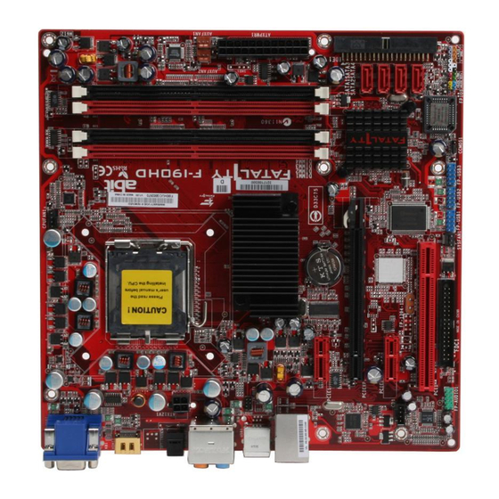
Page 10: Motherboard Layout
1.2 Motherboard Layout F-I90HD... -
Page 11: Choosing A Computer Chassis
Install the motherboard with screws and have them tightened. To prevent shorting the PCB circuit, ※ please REMOVE the metal studs or spacers if they are already fastened on the chassis base and are without mounting-holes on the motherboard to align with. F-I90HD... -
Page 12: Checking Jumper Settings
For incorrect CPU ratio/clock settings in the BIOS, press <Del> key to enter the BIOS setup menu right after powering on system. Set the CPU operating speed back to its default or an appropriate value. Save and exit the BIOS setup menu. F-I90HD... - Page 13 Enter the BIOS setup menu. Reconfigure the setup parameters if necessary. CAUTION: Danger of explosion may arise if the battery is incorrectly renewed. ※ Renew only with the same or equivalent type recommended by the battery ※ manufacturer. Dispose of used batteries according to the battery manufacturer’s instructions. ※ F-I90HD...
-
Page 14: Connecting Chassis Components
A minimum power of 300W or higher is recommended. ATX12V1: ATX 12V 4-Pin Power Connector This connector supplies power to CPU. The system will not start without connecting power to this one. F-I90HD... -
Page 15: Front Panel Switches & Indicators Headers
Connects to the Suspend LED cable (if there is one) of chassis front panel. • PWR (Pin 6, 8): Connects to the Power Switch cable of chassis front panel. • PLED (Pin 16, 18, 20): Connects to the Power LED cable of chassis front panel. F-I90HD... -
Page 16: Fan Power Connectors
These connectors each provide power to the cooling fans installed in your system. • CPUFAN1: CPU Fan Power Connector • SYSFAN1: System Fan Power Connector • AUXFAN1~2: Auxiliary Fan Power Connector These fan connectors are not jumpers. DO NOT place jumper caps on these ※ connectors. F-I90HD... -
Page 17: Installing Hardware
2. Use your right-thumb to raise the load plate. Lift it up to fully open position. 4. Visually inspect if the CPU is seated well into the socket. The alignment key must be located in the notch of package. F-I90HD... - Page 18 7. Secure the lever with the hook under retention tab. A higher fan speed will be helpful for better airflow and heat-dissipation. ※ Nevertheless, stay alert to not touch any heatsink since a high temperature generated by the working system is still possible. 1-10 F-I90HD...
-
Page 19: Ddr2 Memory Slots
DIMM module. Static electricity can damage the electronic components of the computer or ※ optional boards. Before starting these procedures, ensure that you are discharged of static electricity by touching a grounded metal object briefly. F-I90HD 1-11... -
Page 20: Connecting Peripheral Devices
Make sure to configure the “Master” and “Slave” relation before connecting ※ two drives by one single ribbon cable. The red line on the ribbon cable must be aligned with pin-1 on both the IDE port and the hard-drive connector. 1-12 F-I90HD... -
Page 21: Serial Ata Connectors
SATA device and connect the other end from the power supply. The motherboard in this photo is served for DEMO only, and may not be the ※ same type or model as the one described in this user’s manual. F-I90HD 1-13... -
Page 22: Additional Usb 2.0 Port Headers
Each header supports 2x additional USB 2.0 ports by connecting bracket or cable to the rear I/O panel or the front-mounted USB ports of your chassis. Pin Assignment Pin Assignment Data0 - Data1 - Data0 + Data1 + Ground Ground Make sure the connecting cable bears the same pin assignment. ※ 1-14 F-I90HD... -
Page 23: Internal Audio Connectors
Pin 4 “AVCC” of this header. Pin Assignment Pin Assignment (HD AUDIO) (AC’97 AUDIO) MIC2 L MIC In AGND MIC2 R MIC Power AVCC FRO-R Line Out (R) MIC2_JD F_IO_SEN FRO-L Line Out (L) LINE2_JD F-I90HD 1-15... - Page 24 The audio driver is originally configured to support HD Audio. For AC’97 audio connection, you may: Right-click the “Realtek HD Audio Manager” icon system tray. Click “Audio I/O” tab, and then click “Connector Settings”. Click “Disabled front panel jack detection”, and then click “OK” to confirm. 1-16 F-I90HD...
-
Page 25: Pci And Pci Express X16, X1 Slots
Install PCI Express X16 graphics card into slot “PCIEXP1”. Install PCI Express X1 card into slot “PCIE1” and/or “PCIE2”. Install PCI card into slot “PCI1”. 1.8.7 TV-OUT Header This header is reserved for connecting an optional TV-Out card (Model name: HDTV-10). F-I90HD 1-17... -
Page 26: Onboard Indicators And Buttons
1.9 Onboard Indicators and Buttons 1.9.1 LED Indicators • 5VSB: This LED lights up when the power supply is connected with power source. • VCC: This LED lights up when the system power is on. 1-18 F-I90HD... -
Page 27: Connecting Rear Panel I/O Devices
Line-Out: Connects to the front left and front right channel in the 7.1-channel or regular 2-channel audio system. Mic-In: Connects to the plug from external microphone. • LAN1: Connects to Local Area Network. • USB1/USB2: Connects to USB devices such as scanner, digital speakers, monitor, mouse, keyboard, hub, digital camera, joystick etc. F-I90HD 1-19... - Page 28 For more information: www.abit.com.tw 1-20 F-I90HD...
-
Page 29: Bios Setup
In order to increase system stability and performance, our engineering staff is ※ constantly improving the BIOS menu. The BIOS setup screens and descriptions illustrated in this manual are for your reference only, and may not completely match with what you see on your screen. F-I90HD... -
Page 30: Softmenu Setup
This item selects the front side bus frequency. Due to the specification limit of the CPU you installed, the speed you set over ※ its standard bus speed is supported, but not guaranteed. Multiplier Factor This item displays the multiplier factor for the CPU you installed. F-I90HD... - Page 31 This option allows you to switch between the default and user-defined voltages. Leave this setting at default unless the current voltage setting cannot be detected or is not correct. The option “User Define” enables you to select the following voltages manually. CPU Core Voltage DDR2 Voltage NB 1.2 Voltage NB 1.8 Voltage F-I90HD...
-
Page 32: Standard Cmos Features
IDE HDD Auto-Detection Press Enter Item Help IDE Channel 1 Master Auto Access Mode Auto Capacity 0 MB Cylinder Head Precomp Landing Zone Sector :Move Enter:Select +/-/PU/PD:Value F10:Save ESC:Exit F1:General Help F5: Previous Values F6: Fail-Safe Defaults F7: Optimized Defaults F-I90HD... - Page 33 This item determines whether the system stops if an error is detected during system boot-up. [All Errors]: The system-boot will stop whenever the BIOS detect a non-fatal error. [No Errors]: The system-boot will not stop for any error detected. F-I90HD...
- Page 34 640K for systems with 640K or more memory size installed on the motherboard. Extended Memory This item displays the amount of extended memory detected during system boot-up. Total Memory This item displays the total memory available in the system. F-I90HD...
-
Page 35: Advanced Bios Features
- Thermal Management Thermal Monitor 1 Limit CPUID MaxVal Disabled C1E Function Enabled Execute Disable Bit Enabled Virtualization Technology Enabled EIST Function Enabled :Move Enter:Select +/-/PU/PD:Value F10:Save ESC:Exit F1:General Help F5: Previous Values F6: Fail-Safe Defaults F7: Optimized Defaults F-I90HD... - Page 36 Set [Boot Other Device] to [Enabled] if you wish to boot from another device other than these three items. Boot Up Floppy Seek When set to [Enabled], the BIOS will check whether the floppy disk drive is installed or not. F-I90HD...
- Page 37 A larger value will give more delay time to the device for which to initialize and to prepare for activation. Full Screen LOGO Show This item determines to show the full screen logo when booting. Disable Unused PCI Clock This option disables the clock of PCI slot that is not in use. F-I90HD...
-
Page 38: Advanced Chipset Features
“HDMI Port” under the [Normal] selection will cause the screen flickering. Select the correct one for your display device. UMA Frame Buffer Size This item selects the size of memory pre-allocated for frame buffer. 2-10 F-I90HD... - Page 39 GFX Link Width This item specifies the bandwidth for slot [PCIEXP1]. F-I90HD 2-11...
-
Page 40: Integrated Peripherals
This item allows you to enable or disable the primary and secondary IDE controller. Select [Disabled] if you want to add a different hard drive controller. OnChip SATA Controller This option enables or disables the onchip SATA controller. 2-12 F-I90HD... - Page 41 Select [BIOS] for the legacy operating system (such as DOS) that does not support USB keyboard. USB Mouse Support via Select [BIOS] for the legacy operating system (such as DOS) that does not support USB mouse. OnChip Audio Controller This option enables or disables the audio controller. F-I90HD 2-13...
-
Page 42: Onboard Pci Device
Network Controller This option enables or disables the LAN controller. Invoke Boot Agent This item allows you to use the boot ROM (instead of a disk drive) to boot up the system and access the local area network directly. 2-14 F-I90HD... -
Page 43: Power Management Setup
Wake Up by Wake# of PCIe When set to [Enabled], access through the add-on PCI Express card can remotely wake up the system that was in Soft-Off condition. The PCI Express card must support the wake up function. F-I90HD 2-15... - Page 44 Restore On AC Power Loss This item selects the system action after an AC power failure. [Power Off]: When power returns after an AC power failure, the system’s power remains off. You must press the Power button to power-on the system. 2-16 F-I90HD...
- Page 45 If the system’s power is off when AC power failure occurs, it will remain off when power returns. If the system’s power is on when AC power failure occurs, the system will power-on when power returns. F-I90HD 2-17...
-
Page 46: Pnp/Pci Configurations
:Move Enter:Select +/-/PU/PD:Value F10:Save ESC:Exit F1:General Help F5: Previous Values F6: Fail-Safe Defaults F7: Optimized Defaults PCI/VGA Palette Snoop This item determines whether the MPEG ISA/VESA VGA cards can work with PCI/VGA or not. [Enabled]: MPEG ISA/VESA VGA cards work with PCI/VGA. 2-18 F-I90HD... - Page 47 PCI device can conduct transactions for a longer time and thus improve the effective PCI bandwidth. For better PCI performance, you should set the item to higher values. Maximum Payload Size This item sets the maximum TLP payload size for the PCI Express devices. F-I90HD 2-19...
-
Page 48: Pc Health Status
This item allows you to control the CPUFAN speed. When set to [Enabled], the following items become configurable. FanEQ Target Temp. This item sets the temperature mark for the “CPU FanEQ” function to take effect. FanEQ Temp. Tolerance This item sets the temperature tolerance range for the item “FanEQ Target Temp.”. 2-20 F-I90HD... - Page 49 Shutdown When FAN Fail When set to [Enabled], the system will be shut down if the CPU fan is not running. CPU Shutdown Temperature This item sets the temperature that will shutdown the system automatically in order to prevent system overheats. F-I90HD 2-21...
-
Page 50: Load Fail-Safe Defaults
This option protects the BIOS configuration or restricts access to the computer itself. 2.12 Save & Exit Setup This option saves your selections and exits the BIOS setup menu. 2.13 Exit Without Saving This option exits the BIOS setup menu without saving any changes. For more information: www.abit.com.tw 2-22 F-I90HD... -
Page 51: Driver & Utility
Browse CD]: Click to browse the contents of this “Driver-&-Utility CD”. • Close]: Click to exit this installation menu. The Windows will automatically search for current and updated software by looking up your computer. When this “Found New Hardware Wizard” window appears. Click [Cancel] to start the following procedures. F-I90HD... -
Page 52: Ati South Bridge Driver
Please install this driver first before installing the ATi VGA driver. ※ To install this program: Click on the [Drivers] tab in the installation menu screen. Click the [Microsoft.NET Framework] item. The installation screen appears. Follow the prompts on the screen to complete installation. F-I90HD... -
Page 53: Ati Vga Driver
This program enables the [LAN1] connector function. To install this program: Click on the [Drivers] tab in the installation menu screen. Click the [Realtek LAN Driver] item. The installation screen appears. Follow the prompts on the screen to complete installation. F-I90HD... -
Page 54: Realtek Audio Driver
Sound Manager icon located at the desktop shortcut. Click item “Sound Manager”. The Realtek HD Audio Manager appears. Click the [Audio I/O] tab. Click the pull down menu to select the channel configuration. Click [OK] button to apply the Audio I/O settings and exit. F-I90HD... -
Page 55: Hdmi Audio Driver
Double-click the “Sounds and Audio Devices” icon through Windows’ Control Panel to enter its properties. You may also get in the “Multimedia” menu directly by right-clicking your mouse button on the “Sound Manager” icon located at the desktop shortcut. F-I90HD... -
Page 56: Ati Ahci Compatible Raid Driver
Follow the prompts on the screen to complete installation. 3.9 USB 2.0 Driver There is no need to install this driver for Windows 2000 with Service Pack 4, ※ Windows XP with Service Pack 1, or their later version. F-I90HD... -
Page 57: Abit Eq (The Hardware Doctor Utility)
Restart the system for the program to take effect. Execute the ABIT EQ by entering the Windows Menu [Start] [All Programs] [abit] [ABITEQ]. The ABIT EQ shows you the status of Voltage, Fan Speed, and Temperature readings as well. F-I90HD... -
Page 58: Flashmenu (Bios Update Utility)
Execute the FlashMenu by entering the Windows Menu [Start] [All Programs] [abit] [FlashMenu]. This FlashMenu screen appears. You can easily update the BIOS from clicking [Update From File], [One Click LiveUpdate], or [LiveUpdate Step by Step] button. F-I90HD... -
Page 59: Build Ati Sata Driver Disk Under Windows Environment
Click the [ATi SATA Driver Disk Maker] item. The installation screen appears. Insert one blank floppy disk to the selected floppy drive and click [Build]. Click [OK] to finish building the SATA Driver Disk. Click [Exit] to exit this utility. F-I90HD... -
Page 60: Build Ati Sata Driver Disk Under Dos Environment
Now you have this driver disk ready for installing Windows Operating System. Insert this floppy disk to floppy drive and press <F6> key when the screen instruction prompts you to install a third-party SCSI or RAID driver. 3-10 F-I90HD... -
Page 61: Multilingual Quick Installation Guide
[HLED]: Connecte au câble en nappe de la DEL du lecteur du • LAN1: Connecte au réseau local d’ordinateurs. disque dur (HDD). • USB1/USB2: Connecte aux unités du protocole USB. • [RST]: Connecte au câble en nappe de l’interrupteur de réinitialisation. F-I90HD... -
Page 62: Deutsch//Kurze Installationsanleitung
IEEE1394: Anschluss für Geräte mit IEEE1394-Protokoll. • Anschließen der Gehäusekomponenten LAN1: Anschluss für ein ortsgebundenes Netzwerk. • USB1/USB2: Anschluss für USB-Geräte wie Scanner, • ATX-Stromversorgung: [ATXPWR1], [ATX12V1] digitale Lautsprecher, Monitor, Maus, Tastatur, Hub, Lüfteranschlüsse (FAN): [CPUFAN1], [SYSFAN1], Digitalkamera, Joystick, etc. [AUXFAN1], [NBFAN1] F-I90HD... -
Page 63: Italiano//Guida All'installazione Rapida
Connettori del pannello frontale: [FPIO1] digitali, joystick ecc. • [HLED]: collega al cavo LED disco rigido. • [RST]: collega al cavo Interruttore ripristino. • [SPKR]: collega al cavo delle casse di sistema. F-I90HD... -
Page 64: Español//Guía Rápida De Instalación
• [HLED]: Conecte el cable del LED del disco duro. • [RST]: Conecte el cable del interruptor de reinicio. • [SPKR]: Conecte el cable del altavoz del sistema. • [SLED]: Conecte el cable del LED de suspensión. F-I90HD... -
Page 65: Português//Guia De Instalação Rápida
Conectores da ventoinha: [CPUFAN1], [SYSFAN1], [AUXFAN1], • USB1/USB2: Ligação de dispositivos USB tais como scanners, [NBFAN1] colunas digitais, monitor, rato, teclado, hub, câmara digital, joystick,etc. Conectores de painel frontal: [FPIO1] • [HLED]: Faz a ligação ao cabo do LED da unidade de disco rígido. F-I90HD... -
Page 66: Русский//Краткое Руководство По Установке
сканер, цифровые динамики, монитор, мышь, клавиатура, • [HLED]: Соединяется с кабелем HDD LED. хаб, цифровая камера, джойстик и т.д. • [RST]: Соединяется с кабелем включателя перезагрузки. • [SPKR]: Соединяется с кабелем системного динамика. • [SLED]: Соединяется с кабелем индикатора приостановки. F-I90HD... -
Page 67: Eesti//Kiirpaigaldusjuhend
Ventilaatorite konnektorid: [CPUFAN1], [SYSFAN1], USB1/USB2: Ühendage USB-seadmega, nagu skanner, • [AUXFAN1], [NBFAN1] digitaalkõlarid, monitor, hiir, klaviatuur, jaotur, Esipaneeli konnektorid: [FPIO1] digitaalkaamera, juhtkang jne. [HLED]: Ühendage HDD LED-kaabliga. • [RST]: Ühendage lähtestusnupu (Reset) kaabliga. • [SPKR]: Ühendage süsteemikõlari kaabliga. • F-I90HD... -
Page 68: Latviski//Ātrās Instalēšanas Instrukcija
• VENTILATORA savienotāji: [CPUFAN1], [SYSFAN1], USB1/USB2: Pievieno USB ierīces, piemēram, skeneri, • [AUXFAN1], [NBFAN1] ciparu skaļruņus, monitoru, peli, klaviatūru, centrmezglu, Priekšējā paneļa savienotāji: [FPIO1] ciparu kameru, kursorsviru. [HLED]: Pievieno HDD LED kabeli. • [RST]: Pievieno atiestates slēdža kabeli. • F-I90HD... -
Page 69: Lietuvių//Trumpas Instaliavimo Vadovas
Priekinio panelio jungtys: [FPIO1] skeneris, skaitmeniniai garsiakalbiai, vaizduoklis, pelė, [HLED]: Sujunkite su HDD LED kabeliu. • klaviatūra, koncentratorius, skaitmeninis fotoaparatas, [RST]: Sujunkite su pakartotinos kelties jungiklio kabeliu. • valdymo svirtis ir pan. [SPKR]: Sujunkite su sistemos garsiakalbio kabeliu. • F-I90HD... -
Page 70: Polski//Instrukcja Szybkiej Instalacji
USB1/USB2: Podłączenie urządzeń USB takich jak skaner, Złącza WENTYLATOR (FAN): [CPUFAN1], [SYSFAN1], głośniki cyfrowe, monitor, mysz, klawiatura, hub, kamera cyfrowa, [AUXFAN1], [NBFAN1] joystick itd. Złącza panela przedniego: [FPIO1] • [HLED]: Podłączenie kabla HDD LED. • [RST]: Podłączenie kabla przełącznika restartu. 4-10 F-I90HD... -
Page 71: Magyar//Gyorstelepítési Útmutató
[HLED]: Csatlakoztassa a HDD LED kábelhez. • billentyűzet, központi elosztóhoz, digitális fényképezőgéphez, [RST]: Csatlakoztassa a reszettelés-kapcsoló kábeléhez. • botkormányhoz, stb. [SPKR]: Csatlakoztassa a rendszerhangszóró kábeléhez. • [SLED]: Csatlakoztassa a LED szüneteltet kábelhez • F-I90HD 4-11... -
Page 72: Türkçe//Hızlı Kurulum Kılavuzu
ATX Güç Kaynağı: [ATXPWR1], [ATX12V1] USB1/USB2: Tarayıcı, dijital hoparlör, monitör, fare, klavye, • dijital kamera, joystick vb. gibi USB aygıtlarını bağlamak FAN Konnektörleri: [CPUFAN1], [SYSFAN1], [AUXFAN1], [NBFAN1] içindir. Ön Panel Konnektörleri: [FPIO1] [HLED]: Sabit Disk Sürücü LED kablosuna bağlayın. • 4-12 F-I90HD... - Page 73 دﻟﻴﻞ اﻟﺘﺮآﻴﺐ اﻟﺴﺮﻳﻊ اﻟﻠﻐﺔ اﻟﻌﺮﺑﻴﺔ 4.13 F-I90HD 4-13...
- Page 74 راهﻨﻤﺎﯼ ﻧﺼﺐ ﺳﺮﻳﻊ ﻓﺎرﺳﯽ 4.14 4-14 F-I90HD...
-
Page 75: 日本語//クイックインストールガイド
AUDIO1: 7.1ch オーディオ 入力/出力 コネクター。 • IEEE1394: IEEE1394 プロトコルのデバイスに接続 ATX 電源装置: [ATXPWR1]、[ATX12V1] します。 ファンコネクタ: [CPUFAN1], [SYSFAN1], [AUXFAN1], • LAN1: 構内通信網(LAN)に接続します。 [NBFAN1] • USB1/USB2: スキャナ、デジタルスピーカー、モニ タ、マウス、キーボード、ハブ、デジタルカメラ、ジ 前面パネルコネクタ: [FPIO1] ョイスティックなどの USB デバイスに接続します。 • [HLED]: HDD LED ケーブルに接続 • [RST]: リセットスイッチケーブルに接続 F-I90HD 4-15... -
Page 76: 한국어//빠른 설치 가이드
USB1/USB2: 스캐너, 디지털 스피커, 모니터, 마우스, 팬 연결부: [CPUFAN1], [SYSFAN1], [AUXFAN1], [NBFAN1] 키보드, 허브, 디지털 카메라, 조이스틱 등과 같은 전면 판넬 연결 컨넥터: [FPIO1] USB 장치들에 연결하십시오. • [HLED]: HDD LED 케이블에 연결하세요. • [RST]: 초기화 스윗치 케이블에 연결하세요. 4-16 F-I90HD... -
Page 77: Bahasa Malaysia//Panduan Pemasangan Ringkas
USB1/USB2: Sambungkan ke peranti USB seperti • Penyambung KIPAS: [CPUFAN1], [SYSFAN1], [AUXFAN1], pengimbas , pembesar suara digital, monitor, tetikus, papan [NBFAN1] kekunci, hab, kamera digital, kayu bedik dan sebagainya. Penyambung Panel Depan: [FPIO1] [HLED]: Sambungkan ke kabel HDD LED. • F-I90HD 4-17... -
Page 78: ไทย//คู ่ ม ื อ การติ ด ตั ้ ง อย่ า งย่ อ
กล้ อ งถ่ า ยภาพยนต์ ด ิ จ ิ ต อล, ฮั บ , จอยสติ ก ส์ เป็ น ต้ น จุ ด ต่ อ กั บ หน้ า ปั ด : [FPIO1] [HLED]: ต่ อ เข้ า กั บ สาย HDD LED • 4-18 F-I90HD... -
Page 79: 繁體中文
• 內建 PCIE Gigabit LAN RoHS • 100%無鉛處理與 RoHS 相容 音效 • 內建 7.1 聲道 HD 音效 其他 • Micro ATX 主機板規格(244mm x 串列 ATA 244mm) • 4 組 SATA 3Gb/s 支援 SATA RAID 0、1、 以及 0+1 的功能 ※ 本手冊的規格與資訊若有變動,恕不另行通知。 F-I90HD 4-19... -
Page 80: 快速安裝略說
裝置的 S/PDIF 輸出。 [NBFAN1]:北橋冷卻風扇插座。 • AUDIO1: 7.1 聲道音效輸入/輸出連接。 • 前面板插座:[FPIO1] IEEE1394:連接 IEEE1394 通訊協定裝置。 • [HLED]:連接至硬碟 LED 連接線。 • LAN1:連接區域網路。 • [RST]:連接至重新啟動開關連接線。 • USB1/USB2:連接 USB 裝置,例如掃描器、數位喇 • [SPKR]:連接至系統喇叭連接線。 • 叭、顯示器、滑鼠、鍵盤、集線器、數位相機或搖 [SLED]:連接至暫停 LED 連接線。 • 桿等。 [PWR]:連接至電源開關連接線。 • [PLED]:連接至電源 LED 連接線。 • 4-20 F-I90HD... -
Page 81: 简体中文
• 内建 PCIE Gigabit LAN RoHS 音效 • 100%无铅工艺,符合 RoHS 规范 • 内建 7.1 声道 HD 音效 其它 串行 ATA • Micro ATX 主板规格(244mm x 244mm) • 4 组 SATA 3Gb/s 支持 SATA RAID 0、1、 以及 0+1 功能 ※ 本手册的规格与信息若㈲变动,恕不另行通知。 F-I90HD 4-21... -
Page 82: 快速安装略说
[NBFAN1]:北桥冷却风扇连接器。 • 接,用于连接数码多媒体设备。 AUDIO1:7.1 声道音效输入/输出连接。 • 前面板连接器:[FPIO1] IEEE1394:连接支持 IEEE1394 ㈿议的设备。 [HLED]:连接 HDD LED 电缆。 • • LAN1:连接到局域网。 • [RST]:连接复位开关电缆。 • USB1/USB2:连接 USB 设备,如扫描仪、数码扬声 • [SPKR]:连接系统扬声器电缆。 • [SLED]:连接挂起 LED 电缆。 器、㈼视器、鼠标、键盘、集线器、数码相机、操 • [PWR]:连接电源开关电缆。 纵杆等。 • [PLED]:连接电源 LED 电缆。 • 4-22 F-I90HD... -
Page 83: Appendix
If the situation remains the same, try Step 3. Step 3. The same procedure as Step 2, but while discharging the CMOS data, pull out the ATX power connectors from motherboard and remove the button battery during CMOS discharge. F-I90HD... - Page 84 Example: Intel 650 3.4GHz (OC FSB=220MHz) • Memory brand: Type in the brand and model name of your memory module. Example: Memory brand: Kingston (KVR533D2N4/1G) • Memory size: Type in the size of your memory module. Example: 512M* 4PCS F-I90HD...
- Page 85 Q. Is the motherboard dead? Do I need to return it to where I bought from or go through an RMA process? A: After you have gone through the troubleshooting procedures, yet the problem still exists, or you find an evident damage on the motherboard, please contact our RMA center. (http://www2.abit.com.tw/page/en/contact/index.php?pFUN_KEY=18000&pTITLE_IMG) F-I90HD...
-
Page 86: Technical Support Form
5.1.2 Technical Support Form Region: E-mail: First name: Last Name: Subject: Motherboard: BIOS Version: CPU: Memory brand: Memory size: Memory configuration: Graphics card: Graphics driver version: Power supply maker: Power supply wattage: Storage devices: Optical devices: Other devices: Operating system: Problem description: F-I90HD... -
Page 87: Universal Abit Contact Information
Universal ABIT (Rep. office) Universal ABIT NL B.V. No.50, Valiasr Computer Center, Valiasr St. Jan van Riebeeckweg 15, 5928LG, Tehran Iran Venlo, The Netherlands Tel: 98-21-88943672 Tel: 31-77-3204428 Fax: 98-21-88941655 Fax: 31-77-3204420 Contact: Alireza Khoshdel Chamber of Commerce Venlo – number 12062448 F-I90HD... - Page 88 Johnathan “Fatal1ty” Wendel P/N: 4310-0000-24 Rev. 1.00...
Need help?
Do you have a question about the F-I90HD and is the answer not in the manual?
Questions and answers