Sun Microsystems Sun Fire X4100 Service Manual
Hide thumbs
Also See for Sun Fire X4100:
- Manual (100 pages) ,
- Product notes (82 pages) ,
- Installation manual (50 pages)
Table of Contents

Related Manuals for Sun Microsystems Sun Fire X4100


Summary of Contents for Sun Microsystems Sun Fire X4100
- Page 1 Sun Fire ™ X4100/X4100 M2 and X4200/X4200 M2 Servers Service Manual Sun Microsystems, Inc. www.sun.com Part No. 819-1157-23 August 2009, Revision A Submit comments about this document by clicking the Feedback[+] link at: http://docs.sun.com...
- Page 2 Etats-Unis et dans d'autres pays et licenciée exclusivement par X/Open Company, Ltd. Sun, Sun Microsystems, le logo Sun, Java, Netra, Solaris, Sun Ray, Sun Fire Servers, Sun Fire X4100 Server, X4100 M2 Server, X4200 Server, X4200 M2 Server, SunVTS, le logo Java Coffee Cup, le logo Solaris, Sun et Java sont des marques de fabrique ou des marques déposées de Sun Microsystems, Inc., ou ses filiales, aux Etats-Unis et dans d'autres pays.
-
Page 3: Table Of Contents
Contents Preface xi Introduction 1–1 Features of the Servers 1–1 Replaceble Components Overview 1–4 1.2.1 Sun Fire X4100/X4100 M2 Server Front Panel 1–4 1.2.2 Sun Fire X4100/X4100 M2 Server Back Panel 1–4 1.2.3 Sun Fire X4100/X4100 M2 Server Components 1–6 1.2.4... - Page 4 BIOS Advanced Menu, AMD PowerNow Configuration 2–31 2.3.6.17 BIOS Advanced Menu Remote Access Configuration Screen 2–32 2.3.6.18 BIOS Advanced Menu USB Configuration Screen 2–33 2.3.6.19 BIOS PCI/PnP Menu 2–35 Sun Fire X4100/X4100 M2 and X4200/X4200 M2 Servers Service Manual • August 2009...
- Page 5 2.3.6.20 BIOS Boot Menu Main Screen 2–37 2.3.6.21 BIOS Boot Settings Configuration Screen 2–38 2.3.6.22 BIOS Boot Menu Boot Device Priority Screen 2–39 2.3.6.23 BIOS Boot Menu Hard Disk Drives Screen 2–41 2.3.6.24 BIOS Boot Menu Removable Drives Screen 2–42 2.3.6.25 BIOS Boot Menu CD/DVD Drives Screen 2–43 2.3.6.26...
- Page 6 3.12.13 Replacing the Drives Backplane 3–57 3.12.14 DIMM Population Rules 3–61 3.12.14.1 Supported DIMM Configurations 3–63 3.12.14.2 Installing DIMMs Into a Single-CPU System 3–64 3.12.15 Replacing DIMMs 3–65 Sun Fire X4100/X4100 M2 and X4200/X4200 M2 Servers Service Manual • August 2009...
- Page 7 3.12.20 Replacing the Rear Fan Tray (Sun Fire X4200/X4200 M2 Servers) 3–89 A. System Specifications A–1 Sun Fire X4100/X4100 M2 Specifications A–1 Sun Fire X4200/X4200 M2 Specifications A–3 B. BIOS POST Codes B–1 How BIOS POST Memory Testing Works B–1 Redirecting Console Output B–2...
- Page 8 Device Verify Screen F–15 F.3.8 Advanced Adapter Properties Screen F–17 F.3.9 Advanced Device Properties Screen F–19 F.3.10 PHY Properties Screen F–20 F.3.11 Integrated RAID Configuration and Management Screens F–22 viii Sun Fire X4100/X4100 M2 and X4200/X4200 M2 Servers Service Manual • August 2009...
- Page 9 Synchronizing an Array F–38 F.4.8 Activating an Array F–39 F.4.9 Deleting an Array F–39 F.4.10 Locating a Disk Drive F–40 G. Device Paths G–1 Sun Fire X4100/X4100 M2 Device Paths G–1 Sun Fire X4200/X4200 M2 Device Paths G–2 Index Index–1 Contents...
- Page 10 Sun Fire X4100/X4100 M2 and X4200/X4200 M2 Servers Service Manual • August 2009...
-
Page 11: Product Updates
It is important that you review the safety guidelines in the Sun Fire X4100/X4100 M2 and X4200/X4200 M2 Servers Safety and Compliance Guide (819-1161). Product Updates For product updates that you can download for the Sun Fire X4100 or Sun Fire X4200 servers, go to http://www.sun.com/servers/entry/x4100/downloads.jsp This site contains updates for firmware and drivers, as well as CD-ROM .iso... -
Page 12: Related Documentation
For Solaris and other software documentation, refer to: http://docs.sun.com Documentation, Support, and Training The Sun web site provides information about the following additional resources: Sun Function Support http://www.sun.com/support/index.jsp Training http://www.sun.com/training Warranty http://www.sun.com/service/support/warranty/index.html Sun Fire X4100/X4100 M2 and X4200/X4200 M2 Servers Service Manual • August 2009... -
Page 13: Sun Welcomes Your Comments
Sun is interested in improving its documentation and welcomes your comments and suggestions. You can submit your comments by going to: http://www.sun.com/hwdocs/feedback Please include the title and part number of your document with your feedback: Sun Fire X4100/X4100 M2 and X4200/X4200 M2 Servers Service Manual, 819-1157-23 Preface xiii... - Page 14 Sun Fire X4100/X4100 M2 and X4200/X4200 M2 Servers Service Manual • August 2009...
-
Page 15: Features Of The Servers
This chapter describes the features, main components, and accessories of the Sun Fire™ X4100/X4100 M2 and X4200/X4200 M2 servers. Note – The information in this chapter applies to all Sun Fire X4100/X4100 M2 and X4200/X4200 M2 servers, unless otherwise noted. - Page 16 Sun Fire X4200 M2: • Two 8-lane, low-profile PCIE slots • Four 8-lane PCIE slots • Right angle PCIE risers are provided • One 133-MHz PCIX slot Sun Fire X4100/X4100 M2 and X4200/X4200 M2 Servers Service Manual • August 2009...
- Page 17 Server Features (Continued) TABLE 1-1 Feature or Component Sun Fire X4100/X4100 M2 Servers Sun Fire X4200/X4200 M2 Servers Other I/O Sun Fire X4100: Sun Fire X4200: • Three USB 1.1 ports • Four USB 1.1 ports • One VGA video port •...
-
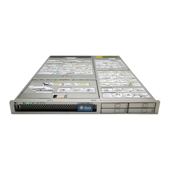
Page 18: Sun Fire X4100/X4100 M2 Server Front Panel
USB port Serial number sticker on bezel Hard disk drives (2) 1.2.2 Sun Fire X4100/X4100 M2 Server Back Panel shows the features of the back panel. FIGURE 1-2 Sun Fire X4100/X4100 M2 and X4200/X4200 M2 Servers Service Manual • August 2009... - Page 19 Sun Fire X4100/X4100 M2 Server Back Panel FIGURE 1-2 Figure Legend Power supplies Grounding post PCI card slots (2) Video connector Serial management port USB connectors (2) 10/100 Ethernet port for net management 10/100/1000 gigabit Ethernet ports (4) Chapter 1...
-
Page 20: Sun Fire X4100/X4100 M2 Server Components
Hard drives (2) (4-drives option available with no DVD-ROM) Fan modules (6) Fan connector boards (2) (not visible—underneath fan modules) PCI-e card slot (2) Graphics-redirect and service processor (GRASP) board Motherboard Sun Fire X4100/X4100 M2 and X4200/X4200 M2 Servers Service Manual • August 2009... - Page 21 Battery DIMMs (up to 4 for each CPU) CPUs and heatsinks (2) Front I/O board Front panel indicator board Sun Fire X4100 M2 Replaceable Component Locations FIGURE 1-4 Figure Legend Power supplies (2) Power distribution board Flex cable (underneath cable retainer)
-
Page 22: Sun Fire X4200/X4200 M2 Server Front Panel
Sun Fire X4200/X4200 M2 Server Front Panel FIGURE 1-5 Figure Legend Power/OK LED Power button DVD-ROM drive USB ports (2) Serial number sticker on bezel Hard disk drives (4) Sun Fire X4100/X4100 M2 and X4200/X4200 M2 Servers Service Manual • August 2009... -
Page 23: Sun Fire X4200/X4200 M2 Server Back Panel
1.2.5 Sun Fire X4200/X4200 M2 Server Back Panel shows the features of the back panel. FIGURE 1-6 Sun Fire X4200/X4200 M2 Server Back Panel FIGURE 1-6 Figure Legend Rear fan tray PCI card slots (5) Grounding post Power supplies (2) Video connector Serial management port USB connectors (2) -
Page 24: Sun Fire X4200/X4200 M2 Server Components
Power supplies (2) Power distribution board Flex cable (underneath cable retainer) Hard disk drive backplane PCIe card slots (4) DVD-ROM drive Hard drives (4) Fan modules (6) 1-10 Sun Fire X4100/X4100 M2 and X4200/X4200 M2 Servers Service Manual • August 2009... - Page 25 Figure Legend Fan connector boards (2) (not visible—underneath fan modules) PCI-X card slot (1) Graphics-redirect and service processor (GRASP) board Motherboard Battery DIMMs (up to 4 for each CPU) CPUs and heatsinks (2) Front I/O board Front panel indicator board Sun Fire X4200 M2 Replaceable Component Locations FIGURE 1-8 Chapter 1...
- Page 26 Front I/O board Front panel indicator board shows the locations of the Sun Fire X4200 M2 server replaceable FIGURE 1-8 components, with the top covers removed. 1-12 Sun Fire X4100/X4100 M2 and X4200/X4200 M2 Servers Service Manual • August 2009...
-
Page 27: Accessory Kits
TABLE 1-2 Item Part Number Sun Fire X4100/X4200 Servers Resource CD 705-7917 Sun Fire X4100 M2/X4200 M2 Servers Tools and Drivers CD Sun Fire X4100/X4200 Servers Bootable Diagnostics CD 705-7852 Sun Fire X4100/X4200 Servers Sun Installation Assistant CD 705-7918 Sun N1 System Manager DVD (depending on availability) -
Page 28: Additional Options And Replaceable Components
CPUs. Do not mix the two different types of CPUs. Always make sure that all CPUs in the server have the same part number. 1-14 Sun Fire X4100/X4100 M2 and X4200/X4200 M2 Servers Service Manual • August 2009... -
Page 29: Powering On The Server
■ Section 2.8, “Updating the BIOS” on page 2-61 ■ Section 2.9, “Power-On Self-Test (POST)” on page 2-61 ■ Note – The information in this chapter applies to all Sun Fire X4100/X4100 M2 and X4200/X4200 M2 servers, unless otherwise noted. -
Page 30: Powering On The Server
When main power is applied to the full server, the Power/OK LED next to the Power FIGURE 2-1 button lights and remains lit. Front Panel of Sun Fire X4100/X4100 M2 Server Sun Fire X4100/X4100 M2 and X4200/X4200 M2 Servers Service Manual • August 2009... -
Page 31: Powering Off The Server
Front Panel of Sun Fire X4200/X4200 M2 Server FIGURE 2-2 Figure Legend Power/OK LED Power button Figure Legend Power/OK LED Power button Powering Off the Server 1. Choose a method for shutting down the server from main power mode to standby power mode. -
Page 32: Changing The Configuration Of A Bios Menu Item
Section B.2, “Redirecting Console Output” on page B-2. Use a terminal (or terminal emulator connected to a computer) through the serial ■ port on the back panel of the server. Sun Fire X4100/X4100 M2 and X4200/X4200 M2 Servers Service Manual • August 2009... -
Page 33: Pci Card Slot Boot Priority
Refer to the section that corresponds to your version of the server: “Sun Fire X4100/X4200 Servers PCI Slot Boot Priority” on page 2-5 ■ “Sun Fire X4100 M2/X4200 M2 Servers PCI Slot Boot Priority” on page 2-5 ■ Section 3.12.16, “Replacing PCI Cards” on page 3-72 for the locations of the PCI slots. -
Page 34: Ethernet Port Device And Driver Naming
“Sun Fire X4100/X4200 Ethernet Port Mapping” on page 6 ■ “Sun Fire X4100 M2/X4200 M2 Ethernet Port Mapping” on page 7 ■ Sun Fire X4100/X4100 M2 and X4200/X4200 M2 Servers Service Manual • August 2009... - Page 35 Sun Fire X4100/X4200 Ethernet Port Mapping shows how various operating systems and interfaces name the four FIGURE 2-4 Ethernet ports shown in FIGURE 2-3 Sun Fire X4100/X4200 Ethernet Port Mapping FIGURE 2-4 BIOS Solaris 10 RHEL e1000 e1000 slot slot...
-
Page 36: Ethernet Port (Nic) Boot Priority
1. NET 0 (Intel NIC 0) 2. NET 1 (Intel NIC 1) 3. NET 2 (Intel NIC 2) 4. NET 3 (Intel NIC 3) Sun Fire X4100/X4100 M2 and X4200/X4200 M2 Servers Service Manual • August 2009... -
Page 37: Bios Option Rom Size Limitation
Sun Fire X4100 M2/X4200 M2 Servers Ethernet Port Boot Priority The order in which the BIOS detects the Ethernet ports during bootup and the corresponding drivers that control those ports are listed below: 1. NET 0 (NVIDIA CK8-04 NIC) 2. NET 1 (NVIDIA IO-04 NIC) 3. - Page 38 Sun Fire X4100/ Settings Configuration Drives Configuration X4200 servers. Event CD/DVD Logging Drives Configuration HyperTransport Configuration IPMI Configuration Event Log Configuration Configuration RemoteAccess Configuration Configuration Configuration 2-10 Sun Fire X4100/X4100 M2 and X4200/X4200 M2 Servers Service Manual • August 2009...
- Page 39 Sun Fire X4100 M2/X4200 M2 BIOS Configuration Utility Menu Tree FIGURE 2-7 Advanced PCI/PnP Security Chipset Main menu Boot menu Exit menu menu menu menu menu PowerNow! NorthBridge Boot Configuration Configuration Configuration Settings SouthBridge Boot Device Configuration Configuration Priority Super I/O Hard Disk Configuration...
-
Page 40: Bios Setup Menu Screens
* Size : 3.0 GB ** F10 Save and Exit ** ESC Exit * System Time [14:23:56] ** ESC Exit * System Date [Wed 07/20/2005] ******************************************************************************** 2-12 Sun Fire X4100/X4100 M2 and X4200/X4200 M2 Servers Service Manual • August 2009... -
Page 41: Bios Advanced Menu Main Screens
2.3.6.2 BIOS Advanced Menu Main Screens Sun Fire X4100/X4200 Servers Main Advanced PCIPnP Boot Security Chipset Exit ******************************************************************************** * Advanced Settings * Options for CPU * *************************************************** * * WARNING: Setting wrong values in below sections may cause system to malfunction. - Page 42 * * Remote Access Configuration * Enter Go to Sub Screen * * * USB Configuration * F1 General Help * F10 Save and Exit * ESC Exit ******************************************************************************** 2-14 Sun Fire X4100/X4100 M2 and X4200/X4200 M2 Servers Service Manual • August 2009...
-
Page 43: Bios Advanced Menu Cpu Configuration Screen
2.3.6.3 BIOS Advanced Menu CPU Configuration Screen Sun Fire X4100/X4200 Servers Advanced ******************************************************************************** * CPU Configuration * This option should * Module Version: 14.05 * remain disabled for * Physical Count: 2 * the normal operation. * Logical Count : 2... - Page 44 General Help * MTRR Mapping [Continuous] * F10 Save and Exit * CPU Overclock in MHz [200] * ESC Exit * Speculative TLB Reload [Enabled] ******************************************************************************** 2-16 Sun Fire X4100/X4100 M2 and X4200/X4200 M2 Servers Service Manual • August 2009...
-
Page 45: Bios Advanced Menu Ide Configuration Screen
2.3.6.4 BIOS Advanced Menu IDE Configuration Screen Sun Fire X4100/X4200 Servers Advanced ******************************************************************************** * IDE Configuration * DISABLED: disables the * * *************************************************** * integrated IDE * OnBoard PCI IDE Controller [Primary] * Controller. * PRIMARY: enables only * * Primary IDE Master... - Page 46 * IO4 SATA1 IDE Interface [Disabled] * +- Change Option * First Boot Device from [P-ATA] * F1 General Help * F10 Save and Exit * ESC Exit ******************************************************************************** 2-18 Sun Fire X4100/X4100 M2 and X4200/X4200 M2 Servers Service Manual • August 2009...
- Page 47 2.3.6.5 BIOS Advanced Menu SuperIO Chipset Configuration Screen Advanced ******************************************************************************** * Configure Smc27X Super IO Chipset * Allows BIOS to Select * *************************************************** * Serial Port1 Base * Serial Port1 Address [3F8/IRQ4] * Addresses. * ** Select Screen * ** Select Item * +- Change Option...
-
Page 48: Bios Advanced Menu Acpi Settings Screen
* ACPI. * ** Select Screen * ** Select Item * +- Change Option * F1 General Help * F10 Save and Exit * ESC Exit ******************************************************************************** 2-20 Sun Fire X4100/X4100 M2 and X4200/X4200 M2 Servers Service Manual • August 2009... -
Page 49: Bios Advanced Menu Acpi Configuration Screen
2.3.6.7 BIOS Advanced Menu ACPI Configuration Screen Advanced ******************************************************************************** * Advanced ACPI Configuration * Enable RSDP pointers * *************************************************** * to 64-bit Fixed System * * ACPI 2.0 Features [Yes] * Description Tables. * ACPI APIC support [Enabled] * ACPI SRAT Table [Enabled] * AMI OEMB table [Enabled]... -
Page 50: Bios Advanced Menu Event Logging Details Screen
Select Screen * ** Select Item * Enter Go to Sub Screen * * F1 General Help * F10 Save and Exit * ESC Exit ******************************************************************************** 2-22 Sun Fire X4100/X4100 M2 and X4200/X4200 M2 Servers Service Manual • August 2009... - Page 51 2.3.6.9 BIOS Advanced Menu HyperTransport Configuration Screen Sun Fire X4100/X4200 Servers Advanced ******************************************************************************** * Hyper Transport Configuration * The HyperTransport * *************************************************** * link will run at this * speed if it is slower * CPU0:CPU1 HT Link Speed [Auto]...
- Page 52 * ** Select Item * PCI-X:IO4 HT Link Width [Auto] * +- Change Option * F1 General Help * F10 Save and Exit * ESC Exit ******************************************************************************** 2-24 Sun Fire X4100/X4100 M2 and X4200/X4200 M2 Servers Service Manual • August 2009...
-
Page 53: Bios Advanced Menu Ipmi Configuration Screen
2.3.6.10 BIOS Advanced Menu IPMI Configuration Screen Advanced ******************************************************************************** * IPMI 2.0 Configuration * View all events in the * * *************************************************** * BMC Event Log. * Status Of BMC Working * * View BMC System Event Log * It will take up to * Reload BMC System Event Log * 60 Seconds approx. - Page 54 00 FF FF * ** Select Screen * ** Select Item * +- Change Option * F1 General Help * F10 Save and Exit * ESC Exit ******************************************************************************** 2-26 Sun Fire X4100/X4100 M2 and X4200/X4200 M2 Servers Service Manual • August 2009...
- Page 55 2.3.6.12 BIOS Advanced Menu IPMI, LAN Configuration Screen Advanced ******************************************************************************** * LAN Configuration. * Enter for IP Address * *************************************************** * Configuration. * Channel Number [01] * Channel Number Status: Channel number is OK * * * IP Address * * MAC Address * * Subnet Mask * ** Select Screen...
-
Page 56: Bios Advanced Menu Ipmi, Pef Configuration Screen
[Disabled] * ** Select Screen * ** Select Item * +- Change Option * F1 General Help * F10 Save and Exit * ESC Exit ******************************************************************************** 2-28 Sun Fire X4100/X4100 M2 and X4200/X4200 M2 Servers Service Manual • August 2009... -
Page 57: Bios Advanced Menu Mps Configuration Screen
2.3.6.14 BIOS Advanced Menu MPS Configuration Screen Advanced ******************************************************************************** * MPS Configuration * MPS Revision * *************************************************** * * MPS Revision [1.4] * ** Select Screen * ** Select Item * +- Change Option * F1 General Help * F10 Save and Exit * ESC Exit... - Page 58 * ** Select Screen * ** Select Item * +- Change Option * F1 General Help * F10 Save and Exit * ESC Exit ******************************************************************************** 2-30 Sun Fire X4100/X4100 M2 and X4200/X4200 M2 Servers Service Manual • August 2009...
- Page 59 2.3.6.16 BIOS Advanced Menu, AMD PowerNow Configuration Advanced ******************************************************************************** * AMD PowerNow Configuration * Enabled/Disabled * *************************************************** * PowerNow * PowerNow [Enabled] * ** Select Screen * ** Select Item * +- Change Option * F1 General Help * F10 Save and Exit * ESC Exit...
- Page 60 [No Delay] * ** Select Screen * ** Select Item * +- Change Option * F1 General Help * F10 Save and Exit * ESC Exit ******************************************************************************** 2-32 Sun Fire X4100/X4100 M2 and X4200/X4200 M2 Servers Service Manual • August 2009...
-
Page 61: Bios Advanced Menu Usb Configuration Screen
2.3.6.18 BIOS Advanced Menu USB Configuration Screen Sun Fire X4100/X4200 Servers Advanced ******************************************************************************** * USB Configuration * Enables support for * *************************************************** * legacy USB. AUTO * Module Version - 2.23.0-7.4 * option disables * legacy support if * USB Devices Enabled :... - Page 62 * * USB Mass Storage Device Configuration * ** Select Screen * ** Select Item * +- Change Option * F1 General Help * F10 Save and Exit * ESC Exit ******************************************************************************** 2-34 Sun Fire X4100/X4100 M2 and X4200/X4200 M2 Servers Service Manual • August 2009...
-
Page 63: Bios Pci/Pnp Menu
2.3.6.19 BIOS PCI/PnP Menu Sun Fire X4100/X4200 Servers Main Advanced PCIPnP Boot Security Chipset Exit ******************************************************************************** * Advanced PCI/PnP Settings ** NO: lets the BIOS * ***************************************************** configure all the * WARNING: Setting wrong values in below sections ** devices in the system. * may cause system to malfunction. - Page 64 Save and Exit * DMA Channel 5 [Available] ** ESC Exit * DMA Channel 6 [Available] * DMA Channel 7 [Available] * Reserved Memory Size [Disabled] ******************************************************************************** 2-36 Sun Fire X4100/X4100 M2 and X4200/X4200 M2 Servers Service Manual • August 2009...
-
Page 65: Bios Boot Menu Main Screen
2.3.6.20 BIOS Boot Menu Main Screen Main Advanced PCIPnP Boot Security Chipset Exit ******************************************************************************** * Boot Settings * Configure Settings * *************************************************** * during System Boot. * * Boot Settings Configuration * * Boot Device Priority * * Hard Disk Drives * * Removable Drives * * CD/DVD Drives * **... -
Page 66: Bios Boot Settings Configuration Screen
[CRHB] * ** Select Screen * ** Select Item * +- Change Option * F1 General Help * F10 Save and Exit * ESC Exit ******************************************************************************** 2-38 Sun Fire X4100/X4100 M2 and X4200/X4200 M2 Servers Service Manual • August 2009... -
Page 67: Bios Boot Menu Boot Device Priority Screen
2.3.6.22 BIOS Boot Menu Boot Device Priority Screen Sun Fire X4100/X4200 Servers Boot ******************************************************************************** * Boot Device Priority * Specifies the boot * *************************************************** * sequence from the * available devices. * 1st Boot Device [CD/DVD Drives] * 2nd Boot Device [Removable Dev.]... - Page 68 [Network:IBA GE Slo] * * ** Select Screen * ** Select Item * +- Change Option * F1 General Help * F10 Save and Exit * ESC Exit ******************************************************************************** 2-40 Sun Fire X4100/X4100 M2 and X4200/X4200 M2 Servers Service Manual • August 2009...
-
Page 69: Bios Boot Menu Hard Disk Drives Screen
2.3.6.23 BIOS Boot Menu Hard Disk Drives Screen Boot ******************************************************************************** * Hard Disk Drives * Specifies the boot * *************************************************** * sequence from the * 1st Drive [#218 ID00 LUN0 FUJ] * available devices. * ** Select Screen * ** Select Item * +- Change Option... -
Page 70: Bios Boot Menu Removable Drives Screen
[USB:AMI Virtual Fl] * available devices. * ** Select Screen * ** Select Item * +- Change Option * F1 General Help * F10 Save and Exit * ESC Exit ******************************************************************************** 2-42 Sun Fire X4100/X4100 M2 and X4200/X4200 M2 Servers Service Manual • August 2009... -
Page 71: Bios Boot Menu Cd/Dvd Drives Screen
2.3.6.25 BIOS Boot Menu CD/DVD Drives Screen Boot ******************************************************************************** * CD/DVD Drives * Specifies the boot * *************************************************** * sequence from the * 1st Drive [CD/DVD:PM-QSI DVD] * available devices. * 2nd Drive [USB:AMI Virtual CD] * * ** Select Screen * ** Select Item * +-... -
Page 72: Bios Security Settings Menu
* Boot Sector Virus Protection [Disabled] * ** Select Screen * ** Select Item * Enter Change * F1 General Help * F10 Save and Exit * ESC Exit ******************************************************************************** 2-44 Sun Fire X4100/X4100 M2 and X4200/X4200 M2 Servers Service Manual • August 2009... -
Page 73: Bios Chipset Menu Main Screen
Select Item * Enter Go to Sub Screen * * F1 General Help * F10 Save and Exit * ESC Exit ******************************************************************************** Sun Fire X4100 M2/X4200 M2 Servers Main Advanced PCIPnP Boot Security Chipset Exit ******************************************************************************** * Options for NB... -
Page 74: Bios Chipset Menu Northbridge Configuration Screen
* F1 General Help Read Write Delay(Trwt) :4 CLK * F10 Save and Exit Read Preamble :7.0 ns * ESC Exit Asynchronous Latency :8 ns ******************************************************************************** 2-46 Sun Fire X4100/X4100 M2 and X4200/X4200 M2 Servers Service Manual • August 2009... -
Page 75: Screen
2.3.6.29 BIOS Chipset Menu NorthBridge Memory Configuration Screen Chipset ******************************************************************************** * Memory Configuration * MEMCLK can be set * *************************************************** * by the code using * Memclock Mode [Auto] * AUTO, or if you use * MCT Timing Mode [Auto] * LIMIT, you can set * User Config Mode [Auto]... -
Page 76: Screen
[Disabled] * ** Select Screen * ** Select Item * +- Change Option * F1 General Help * F10 Save and Exit * ESC Exit ******************************************************************************** 2-48 Sun Fire X4100/X4100 M2 and X4200/X4200 M2 Servers Service Manual • August 2009... -
Page 77: Bios Chipset Menu Southbridge Configuration Screen
2.3.6.31 BIOS Chipset Menu SouthBridge Configuration Screen Sun Fire X4100/X4200 Servers Chipset ******************************************************************************** * South Bridge Chipset Configuration * Enable/disable * *************************************************** * SMBUS 2.0 Controller * 2.0 SM Bus Controller [Enabled] * in South Bridge * Restore on AC/Power Loss... - Page 78 * Restore on AC/Power Loss [Power Off] * F1 General Help * Power Button Behavior [Instant Off] * F10 Save and Exit * ESC Exit ******************************************************************************** 2-50 Sun Fire X4100/X4100 M2 and X4200/X4200 M2 Servers Service Manual • August 2009...
-
Page 79: Bios Chipset Menu Pci-X Configuration Screen
2.3.6.32 BIOS Chipset Menu PCI-X Configuration Screen Sun Fire X4100/X4200 Servers Only Chipset ******************************************************************************** * PCI-X Chipset Configuration * PCI clock is disabled/ * * *************************************************** * enabled for 8131 * Errata 56 PCLK [Enabled] * Errata 56 if a PCI... -
Page 80: Bios Exit Option Menu Screen
Select Screen * ** Select Item * Enter Go to Sub Screen * * F1 General Help * F10 Save and Exit * ESC Exit ******************************************************************************** 2-52 Sun Fire X4100/X4100 M2 and X4200/X4200 M2 Servers Service Manual • August 2009... -
Page 81: Resetting Sp And Bios Passwords Using Jumper P4 Or J12
Resetting SP and BIOS Passwords Using Jumper P4 or J12 The names and locations of this jumper differ between the Sun Fire X4100/X4200 and the X4100 M2/X4200 M2 servers: In Sun Fire X4100/X4200 servers this jumper is P4. See for the FIGURE 2-8 on page 55 ■... - Page 82 Note – If you do not remove this jumper, the ILOM SP and BIOS passwords will be reset every time you power-cycle the server. 2-54 Sun Fire X4100/X4100 M2 and X4200/X4200 M2 Servers Service Manual • August 2009...
- Page 83 Location of Jumpers on the Sun Fire X4100/X4200 Motherboard FIGURE 2-8 Figure Legend P4, Password Clear P5, Force Recovery TP51/TP52, CMOS Clear Chapter 2 Powering On and Configuring BIOS Settings 2-55...
-
Page 84: Resetting The Sp Password
Refer to Sun Fire X4500/X4540 Server Service Manual for instructions. If screen output is displayed, continue to the next step. ■ 2. Enter the ILOM SP U-Boot command interpreter with xyzzy. 2-56 Sun Fire X4100/X4100 M2 and X4200/X4200 M2 Servers Service Manual • August 2009... - Page 85 6. Reboot: boot Using the Force-Recovery Jumper P5 or The names and locations of this jumper differ between the Sun Fire X4100/X4200 and the X4100 M2/X4200 M2 servers: In Sun Fire X4100/X4200 servers this jumper is P5. See for the location.
- Page 86 Note – If you do not remove this jumper, the server will force a recovery of the new BIOS every time that you power cycle the server. 2-58 Sun Fire X4100/X4100 M2 and X4200/X4200 M2 Servers Service Manual • August 2009...
-
Page 87: Using The Clear Cmos Jumper
Using the Clear CMOS Jumper TP51/TP52 or J9 The names and locations of this jumper differ between the Sun Fire X4100/X4200 and the X4100 M2/X4200 M2 servers: In Sun Fire X4100/X4200 servers this is jumper TP51/TP52. See for the FIGURE 2-8 ■... -
Page 88: Using The Reset And Nmi Switches
Service personnel. The names of these switches differ between the Sun Fire X4100/X4200 and the X4100 M2/X4200 M2 servers: In Sun Fire X4100/X4200 servers, the Reset switch is SW3 and the NMI switch is ■ SW2. See for the location. -
Page 89: Updating The Bios
Server Back Panels FIGURE 2-10 Sun Fire X4100/X4100 M2 Server Sun Fire X4200/X4200 M2 Server Figure Legend NMI switch Reset switch Updating the BIOS The BIOS is updated whenever you update the ILOM Service Processor firmware. For instructions on updating the firmware, refer to the Integrated Lights-Out Manager Administration Guide, 819-1160. - Page 90 2-62 Sun Fire X4100/X4100 M2 and X4200/X4200 M2 Servers Service Manual • August 2009...
-
Page 91: Maintaining The Sun Fire Servers
■ Section 3.4, “Powering Off the Server” on page 3-4 ■ Section 3.5, “Removing the Main Cover of the Sun Fire X4100/X4100 M2 Server” ■ on page 3-6 Section 3.6, “Removing the Front Bezel of the Sun Fire X4100/X4100 M2 Server”... -
Page 92: Tools And Supplies Needed
1. Use SSH to log into the SunService account. The default password is changeme. # ssh <SP IP address> -l sunservice # <SP IP Address's> password: changeme Sun Fire X4100/X4100 M2 and X4200/X4200 M2 Servers Service Manual • August 2009... - Page 93 2. At the prompt, enter the servicetool command with options. The options are defined in the following table. # servicetool --fru_update=mainboard <Other Options>=<value> Other Options Value --fru_product_part_number Write a new part number to the FRU. --fru_product_serial_number Write a new serial number to the FRU. --fru_chassis_serial_number Write a new chassis serial number to the FRU.
- Page 94 Power Button and Power/OK LED Location – Sun Fire X4100/X4100 M2 FIGURE 3-1 Figure Legend Power/OK LED Power button Sun Fire X4100/X4100 M2 and X4200/X4200 M2 Servers Service Manual • August 2009...
- Page 95 Power Button and Power/OK LED Location – Sun Fire X4200/X4200 M2 FIGURE 3-2 Figure Legend Power/OK LED Power button Caution – Before unplugging the power cords from the server or handling internal components, attach an electrostatic-discharge (ESD) wrist strap to the grounding post that is built into the rear of the chassis (see for the location).
-
Page 96: Removing The Main Cover Of The Sun Fire X4100/X4100 M2 Server
(or more often in dirty operating environments). Check system heatsinks, fans, and air openings. If necessary, clean systems by carefully brushing, blowing, or vacuuming contaminants from the system. Sun Fire X4100/X4100 M2 and X4200/X4200 M2 Servers Service Manual • August 2009... -
Page 97: Removing The Front Bezel Of The Sun Fire X4100/X4100 M2 Server
Removing the Front Bezel of the Sun Fire X4100/X4100 M2 Server Remove the bezel from the front of the chassis by following these steps: 1. Open the fan bay door and use a No. 2 Phillips screwdriver to unfasten the captive screw that locks the bezel in place. -
Page 98: Removing The Front Cover Of The Sun Fire X4100/X4100 M2 Server
Note – For Sun Fire X4100 servers with the factory-configured option for four hard disk drives: You must remove the top two hard disk drives before reinstalling the front cover to provide clearance for the front cover to slide on the chassis. - Page 99 Removing the Front Cover FIGURE 3-5 Chapter 3 Maintaining the Sun Fire Servers...
-
Page 100: Removing The Main Cover Of The Sun Fire X4200/X4200 M2 Servers
(or more often in dirty operating environments). Check system heatsinks, fans, and air openings. If necessary, clean systems by carefully brushing, blowing, or vacuuming contaminants from the system. 3-10 Sun Fire X4100/X4100 M2 and X4200/X4200 M2 Servers Service Manual • August 2009... -
Page 101: Removing The Front Bezel Of The Sun Fire X4200/X4200 M2 Servers
Removing the Front Bezel of the Sun Fire X4200/X4200 M2 Servers Remove the bezel from the front of the chassis by following these steps. 1. Open the fan bay door and use a No. 2 Phillips screwdriver to unfasten the captive screw that locks the bezel in place. -
Page 102: Removing The Front Cover Of The Sun Fire X4200/X4200 M2 Servers
Note – When you remove any cover, the intrusion switch that is on the front I/O board automatically powers down the system to standby power mode. 3-12 Sun Fire X4100/X4100 M2 and X4200/X4200 M2 Servers Service Manual • August 2009... - Page 103 FIGURE 3-8 3.11 HT Jumper Configuration for Single-CPU Servers (Sun Fire X4100 M2 and X4200 M2) An HT jumper is nothing more than a dummy CPU place-holder in CPU position 1 for single-CPU servers. These jumpers look like regular CPUs, with identical heat sinks, and identical maintenance procedures for replacement.
-
Page 104: Ht Jumper Configuration For Single-Cpu Servers (Sun Fire X4100 M2 And X4200 M2)
Section 3.12.5, “Installing a DVD-ROM Drive Upgrade Kit” on page 3-33 (FRU) ■ Section 3.12.6, “Replacing a Fan Module” on page 3-38 (CRU) ■ Section 3.12.7, “Replacing a Fan Connector Board” on page 3-41 (CRU) ■ 3-14 Sun Fire X4100/X4100 M2 and X4200/X4200 M2 Servers Service Manual • August 2009... -
Page 105: Replacing The Battery
Section 3.12.8, “Replacing the Front Panel Indicator Board” on page 3-44 (CRU) ■ Section 3.12.9, “Replacing the Front I/O Board” on page 3-46 (CRU) ■ Section 3.12.10, “Replacing the Graphics Redirect and Service Processor (GRASP) ■ Board” on page 3-51 (FRU) Section 3.12.11, “Servicetool FRU Update Procedure”... - Page 106 Note – Install the new battery in the holder with the same orientation (polarity) as the battery that you removed. The positive polarity, marked with a “+” symbol, should be facing toward the chassis center. 3-16 Sun Fire X4100/X4100 M2 and X4200/X4200 M2 Servers Service Manual • August 2009...
-
Page 107: Replacing A Cpu And Heatsink (Sun Fire X4100 And X4200 Servers)
3.12.2 Replacing a CPU and Heatsink (Sun Fire X4100 and X4200 Servers) Note – If you have a Sun Fire X4200 M2 server, see “Replacing a CPU and Heatsink (Sun Fire X4100 M2/X4200 M2 Servers)” on page 3-23. Note – This component is an FRU and should be replaced only by qualified service technicians. - Page 108 DIMM 3 DIMM 3 DIMM 1 DIMM 1 DIMM 2 DIMM 2 DIMM 0 DIMM 0 CPU1 CPU0 CPU fault LEDs (2) Front panel of server 3-18 Sun Fire X4100/X4100 M2 and X4200/X4200 M2 Servers Service Manual • August 2009...
- Page 109 5. Remove the CPU and heatsink from the motherboard. a. Hold down the top of the heatsink to prevent it from tipping unevenly while you alternately loosen the two spring-loaded mounting screws that secure the heatsink to the motherboard. Turn the screws 180 degrees at a time, then remove the screws when they are detached.
- Page 110 Pull the CPU socket lever slightly away from the socket. See FIGURE 3-13 d. Pivot the lever up into the fully open, vertical position. Releasing the CPU Socket Lever FIGURE 3-13 3-20 Sun Fire X4100/X4100 M2 and X4200/X4200 M2 Servers Service Manual • August 2009...
- Page 111 e. Lift the CPU out of the socket, leaving the lever in the vertical, open position. FIGURE 3-14 Removing the CPU From the Socket FIGURE 3-14 Alignment triangles 6. Install the new CPU, or reinstall the existing CPU. Note – Mixing CPU speeds or mixing dual-core CPUs with single-core CPUs is not supported.
- Page 112 If necessary, clean systems by carefully brushing, blowing, or vacuuming contaminants from the system. 7. Align the CPU in the socket as shown in FIGURE 3-14 a. Gently insert the CPU pins into the socket. 3-22 Sun Fire X4100/X4100 M2 and X4200/X4200 M2 Servers Service Manual • August 2009...
- Page 113 CPU socket that has the release lever. Also note that the half of the Sun Microsystems logo imprinted on the top of the heatsink will create a complete logo when correctly aligned with the adjacent heatsink.
- Page 114 CPUs. Before replacing a dual-core CPU with a quad-core CPU, check the version strings against those documented in the Sun Fire X4100 M2/X4200 M2 Servers Release Notes. If the existing firmware is not for Software Release 2.0 or later, perform the necessary upgrade before proceeding.
- Page 115 Sun Fire X4200 M2 Designation of CPUs FIGURE 3-16 Back panel of server DIMM 0 DIMM 0 DIMM 1 DIMM 1 DIMM 2 DIMM 2 DIMM 3 DIMM 3 CPU1 CPU0 CPU fault LEDs (2) Chapter 3 Maintaining the Sun Fire Servers 3-25...
- Page 116 Location of the Sun Fire X4200 M2 Heatsink Screws FIGURE 3-17 The four screws are circled in red. Removing the Sun Fire X4200 M2 Heatsink FIGURE 3-18 3-26 Sun Fire X4100/X4100 M2 and X4200/X4200 M2 Servers Service Manual • August 2009...
- Page 117 6. Twist the heatsink slightly to lift it off the board. Turn the heatsink upside down and allow the springs in each of the four mounting holes to fall out into your hand. Note – Set the heatsink upside down on a clean, flat surface to prevent the thermal grease from contaminating other components.
- Page 118 Gently set the CPU onto the pins in the socket. e. When the CPU is fully seated in the socket, pivot the hinged retainer plate down onto the top of the CPU. 3-28 Sun Fire X4100/X4100 M2 and X4200/X4200 M2 Servers Service Manual • August 2009...
- Page 119 f. Pivot the release lever down and into the locked position at the side of the socket. The release lever must lock down the retainer plate as you close the lever. See for a view of how the lever locks down the edge of the FIGURE 3-19 on page 27 plate.
-
Page 120: Replacing The Dvd-Rom Drive
Note – The heatsink is not symmetrical and it must be aligned before you place it on the CPU. Note that the half of the Sun Microsystems logo imprinted on the top of the heatsink will create a complete logo when correctly aligned with the adjacent heatsink. - Page 121 http://sunsolve.sun.com/handbook_pub/Systems/ 1. Click the name and model of your server. 2. On the product page that opens for the server, click Full Components List to view a list of components. Use the following procedure to replace the DVD-ROM drive. 1. Power off the server as described in Section 3.4 on page 3-4 2.
- Page 122 Disconnecting the DVD-ROM Drive Flex Cable Connector (Sun Fire X4100 FIGURE 3-23 Server Shown) Disconnecting the DVD-ROM Drive Flex Cable Connector (Sun Fire X4200 FIGURE 3-24 Server Shown) 3-32 Sun Fire X4100/X4100 M2 and X4200/X4200 M2 Servers Service Manual • August 2009...
-
Page 123: Installing A Dvd-Rom Drive Upgrade Kit
Installation is the reverse of this procedure. When reinstalling screws, tighten to 7 in-lbs (0.8 Nm) using an adjustable torque driver. Note – Sun Fire X4100/X4100 M2: When you replace the DVD-ROM drive, the flex cable, and its cable retainers, reposition the flex cable to the folded position shown in . - Page 124 Using an adjustable torque driver, reinstall the two screws that secure the faceplate to the bezel. Tighten screws to 7 in-lbs (0.8 Nm). 3-34 Sun Fire X4100/X4100 M2 and X4200/X4200 M2 Servers Service Manual • August 2009...
- Page 125 Installing the DVD-Slot Faceplate to the Front Bezel FIGURE 3-26 Chapter 3 Maintaining the Sun Fire Servers 3-35...
- Page 126 8. Connect the unused flex cable connector to the rear of the DVD-ROM drive. FIGURE 3-28 Connecting the DVD-ROM Drive Flex Cable Connector FIGURE 3-28 3-36 Sun Fire X4100/X4100 M2 and X4200/X4200 M2 Servers Service Manual • August 2009...
- Page 127 9. Install the upper cable retainer to the chassis midwall. See FIGURE 3-29 a. Insert the two pegs on the cable retainer into the two holes in the chassis midwall. b. Slide the cable retainer forward until it is locked in place and it is holding the flex cable connector firmly against the rear of the DVD-ROM drive.
-
Page 128: Replacing A Fan Module
2. On the product page that opens for the server, click Full Components List to view a list of components. Use the following procedure to replace a fan module. 3-38 Sun Fire X4100/X4100 M2 and X4200/X4200 M2 Servers Service Manual • August 2009... - Page 129 Caution – The fans are hot-swappable and can be removed and replaced while the system is running. Do not hold the fan bay door open for more than 60 seconds at a time to avoid overheating the server. Remove and replace only one fan at a time. The internal system software designation of the fan connector boards, or fan trays (FT), and fan modules (FM) is shown in (viewed from the front of the...
- Page 130 Check system heatsinks, fans, and air openings. If necessary, clean systems by carefully brushing, blowing, or vacuuming contaminants from the system. Installation is the reverse of this procedure. 3-40 Sun Fire X4100/X4100 M2 and X4200/X4200 M2 Servers Service Manual • August 2009...
-
Page 131: Replacing A Fan Connector Board
3.12.7 Replacing a Fan Connector Board Note – This component is a CRU and can be replaced by anyone. Supported components and their part numbers are subject to change over time. For the most up-to-date list of replaceable components for these servers, refer to: http://sunsolve.sun.com/handbook_pub/Systems/ 1. - Page 132 7. Slide the fan connector board toward the center of the chassis to disconnect it from the front I/O board and to release it from the two locating tabs on the chassis. See FIGURE 3-33 3-42 Sun Fire X4100/X4100 M2 and X4200/X4200 M2 Servers Service Manual • August 2009...
- Page 133 8. Lift the board straight up to remove it from the system. Releasing the Fan Connector Board FIGURE 3-33 Installation is the reverse of this procedure. When reinstalling screws, tighten to 7 in-lbs (0.8 Nm) using an adjustable torque driver. Chapter 3 Maintaining the Sun Fire Servers 3-43...
-
Page 134: Replacing The Front Panel Indicator Board
Note – Always unfasten the bezel’s securing screw before removing the bezel. 5. Remove the front cover as described in Section 3.7 on page 3-8 Section 3.10 on page 3-12 3-44 Sun Fire X4100/X4100 M2 and X4200/X4200 M2 Servers Service Manual • August 2009... - Page 135 6. Unfasten the two screws that secure the front panel indicator board to the chassis. For details, see FIGURE 3-34 Unfastening the Front Panel Indicator Board Screws FIGURE 3-34 7. While supporting the indicator board with your right hand, use your left hand to gently push the indicator board toward the center of the chassis to disconnect it from the front I/O board.
-
Page 136: Replacing The Front I/O Board
Section 3.10 on page 3-12 7. Remove all six fan modules by lifting each fan module by its plastic strap to disconnect it from its fan connector board. 3-46 Sun Fire X4100/X4100 M2 and X4200/X4200 M2 Servers Service Manual • August 2009... - Page 137 8. Visibly inspect the fans and all air openings for dirt, and clean if necessary. Note – System cooling might be affected by dust and contaminant build-up. Therefore, you should open and check systems approximately every six months (or more often in dirty operating environments). Check system heatsinks, fans, and air openings.
- Page 138 12. Disconnect the front I/O interconnect cable that connects the front I/O board to the motherboard. See FIGURE 3-38 Disconnecting the Interconnect Cable from the Front I/O Board FIGURE 3-38 3-48 Sun Fire X4100/X4100 M2 and X4200/X4200 M2 Servers Service Manual • August 2009...
- Page 139 13. Unfasten the screw that secures the front I/O board to the chassis. See FIGURE 3-39 FIGURE 3-40 Unfastening the Front I/O Board Screw From the Chassis (Sun Fire X4100 FIGURE 3-39 Server Shown) Unfastening the Front I/O Board Screw From the Chassis (Sun Fire X4200...
- Page 140 0.25 inch (6 mm), freeing the board from the two locating tabs at its bottom-left and bottom-right corners. See FIGURE 3-41 FIGURE 3-42 Releasing the Front I/O Board From the Chassis Locating Tabs (Sun Fire FIGURE 3-41 X4100 Server Shown) 3-50 Sun Fire X4100/X4100 M2 and X4200/X4200 M2 Servers Service Manual • August 2009...
-
Page 141: Replacing The Graphics Redirect And Service Processor (Grasp) Board
Releasing the Front I/O Board From the Chassis Locating Tabs (Sun Fire FIGURE 3-42 X4200 Server Shown) 15. Lift the front I/O board straight up and out of the chassis. Installation is the reverse of this procedure. When reinstalling screws, tighten to 7 in-lbs (0.8 Nm) using an adjustable torque driver. - Page 142 Removing the GRASP Board FIGURE 3-43 Figure Legend Power status LED CR1 5. Raise the corner of the GRASP board until it is clear of the locking tab. 3-52 Sun Fire X4100/X4100 M2 and X4200/X4200 M2 Servers Service Manual • August 2009...
-
Page 143: Servicetool Fru Update Procedure
Do not use the SunService account unless you are instructed to do so in a procedure developed by Sun Microsystems. Note – Sun Fire X4100/X4200 servers with SP firmware 10708 and later support the servicetool command. 1. Use SSH to log into the SunService account. The default password is changeme. -
Page 144: Replacing A Drive
Would you like to reboot the service processor now (y|n)? y The system is going down NOW!! Sending SIGTERM to all processes. 3.12.12 Replacing a Drive Note – This component is a hot-swappable CRU. 3-54 Sun Fire X4100/X4100 M2 and X4200/X4200 M2 Servers Service Manual • August 2009... - Page 145 Note – Sun Fire X4100/X4100 M2 only – In , Drive 0 and Drive 1 are FIGURE 3-44 represent the standard system configuration; Drive 2 and Drive 3 are shown to represent the optional factory configuration of four hard drives (no DVD-ROM drive).
- Page 146 Push the drive into the bay until it stops, then close the securing latch to fully engage the connector on the drives backplane. 3-56 Sun Fire X4100/X4100 M2 and X4200/X4200 M2 Servers Service Manual • August 2009...
-
Page 147: Replacing The Drives Backplane
Note – For Sun Fire X4100/X4100 M2 servers with the factory-configured option for four hard disk drives: You must remove the top two hard disk drives before reinstalling the front cover to provide clearance for the front cover to slide on the chassis. - Page 148 8. Unfasten the spring-loaded thumbscrew that secures the flex cable retainer, and remove this retainer from the chassis. See FIGURE 3-46 Removing the Flex Cable Retainer FIGURE 3-46 3-58 Sun Fire X4100/X4100 M2 and X4200/X4200 M2 Servers Service Manual • August 2009...
- Page 149 Removing the Upper Cable Retaine FIGURE 3-47 9. Remove the upper cable retainer from the chassis. Push the retainer toward the rear of the chassis to free it from the keyed openings in the chassis midwall. See FIGURE 3-47 10. Disconnect the flex cable connectors from the rear of the DVD-ROM drive and the drives backplane.
- Page 150 12. Unfasten the screws that secure the drives backplane to the rear of the drive bays. See FIGURE 3-50 13. Remove the drives backplane from the chassis. Removing the Drives Backplane FIGURE 3-50 3-60 Sun Fire X4100/X4100 M2 and X4200/X4200 M2 Servers Service Manual • August 2009...
-
Page 151: Dimm Population Rules
3.12.14 DIMM Population Rules Note – Sun Fire X4100/X4200 servers use only DDR1 DIMM. Sun Fire X4100 M2/X4200 M2 servers use only DDR2 DIMMs. Note – Do not mix single-rank and dual-rank pairs on a CPU memory bank or there will be a 10% loss in performance. - Page 152 Note – The system reports individual DIMM numbers when a memory fault happens. Sun Fire X4100 M2/X4200 M2 The DIMM population rules for Sun Fire X4100 M2/X4200 M2 servers are listed here: Each CPU can support a maximum of four DDR2 DIMMs. ■...
-
Page 153: Supported Dimm Configurations
4 GB 4 GB 8 GB 4 GB 4 GB 4 GB 4 GB 16 GB Supported DIMM Configurations – Sun Fire X4100 M2/X4200 M2, DDR2 TABLE 3-2 Only Total Memory Per Slot 2 Slot 3 Slot 0 Slot 1... -
Page 154: Installing Dimms Into A Single-Cpu System
For information on determining if your system has one or two CPUs, see Section 3.11, “HT Jumper Configuration for Single-CPU Servers (Sun Fire X4100 M2 and X4200 M2)” on page 3-13. 3-64 Sun Fire X4100/X4100 M2 and X4200/X4200 M2 Servers Service Manual • August 2009... -
Page 155: Replacing Dimms
Note – If you are installing 4-GB DIMMs to a Sun Fire X4200 server that did not previously have 4-GB DIMMs installed, you must first install BIOS 36 or later. BIOS 36 was included with Software Release 1.2.1. Refer to the Sun Fire X4100/X4200 Servers Release Notes For Software Release 1.2.1, 819-4344. (This upgrade is not necessary for Sun Fire X4100 M2/X4200 M2 servers.) - Page 156 “Powering Off the Server” on page 3-4. Sun Fire X4100 M2/X4200 M2: The DIMM fault LEDs can be lit for up to one ■ minute without external power. To light the DIMM fault LEDs (from a capacitor on the motherboard) push the small button on the motherboard labeled “DIMM SW2.”...
- Page 157 Sun Fire X4100 M2/X4200 M2 ■ FIGURE 3-52 DIMM slots. DIMM Slot Numbering and Pairing – Sun Fire X4100/X4200 FIGURE 3-51 Back panel of server DIMM 3 DIMM 3 DIMM 1 DIMM 1...
- Page 158 Rotate both DIMM slot ejectors outward as far as they will go. The DIMM is partially ejected from the socket. See FIGURE 3-53 b. Carefully lift the DIMM straight up to remove it from the socket. 3-68 Sun Fire X4100/X4100 M2 and X4200/X4200 M2 Servers Service Manual • August 2009...
- Page 159 Removing a DIMM FIGURE 3-53 Figure Legend Notch 7. To install a DIMM: Note – The Sun Fire X4200 server uses only DDR1 DIMMs. The Sun Fire X4200 M2 server uses only DDR2 DIMMs. a. Ensure that the DIMM slot ejectors at each end of the memory socket are fully open (rotated outward) to accept the new DIMM.
- Page 160 Caution – If you install 4-GB DIMMs in a Sun Fire X4100/X4200 server that did not previously have 4-GB DIMMs, you must replace the gaskets on the main cover to ensure containment of electrical emissions, as described in the next steps. Gasket replacement is not necessary for Sun Fire X4100 M2/X4200 M2 server.
- Page 161 d. Install the remaining gasket to the main cover. Installing a Main Cover Gasket for 4-GB DIMMs FIGURE 3-54 Figure Legend Main cover gasket (1 of 2) Underside of main cover Chapter 3 Maintaining the Sun Fire Servers 3-71...
-
Page 162: Replacing Pci Cards
Section 2.3.2 on page 2-5 Note – Sun Fire X4100/X4100 M2 only: The server is shipped with two PCI risers already installed in the low-profile PCI card sockets. Note – Before you install a card, consult the manufacturer's documentation for system requirements and configuration information for your specific PCI card. - Page 163 Designation and Speeds of PCI Slots – Sun Fire X4100/X4100 M2 FIGURE 3-55 Back panel Back panel PCIE0 PCIX0 PCIX1 (PCIE 8-lane) (100-MHz) (133-MHz) PCIE1 (PCIE 8-lane) CPU1 CPU0 CPU1 CPU0 Front panel Front panel Sun Fire X4100 Sun Fire X4100 M2...
- Page 164 PCI0 = PCIE 8-lane PCI1 = PCIE 8-lane PCI2 = PCIX 133-MHz PCI3 = PCIE 8-lane PCI4 = PCIE 8-lane CPU1 CPU0 Front panel of server 3-74 Sun Fire X4100/X4100 M2 and X4200/X4200 M2 Servers Service Manual • August 2009...
- Page 165 5. Remove the slot cover or PCI card from the slot. See FIGURE 3-58 FIGURE 3-59 a. Disconnect any external cables that are attached to the PCI card. b. Working from the rear of the chassis, pivot open the PCI card latch that covers the PCI card’s rear connector panel.
- Page 166 Pivot the PCI card latch closed over the rear connector panel of the PCI card until it locks. See FIGURE 3-60 FIGURE 3-61 Installing a PCI Card (Sun Fire X4200/X4200 M2 Server Shown) FIGURE 3-60 3-76 Sun Fire X4100/X4100 M2 and X4200/X4200 M2 Servers Service Manual • August 2009...
-
Page 167: Replacing The Motherboard
FIGURE 3-61 3.12.17 Replacing the Motherboard Note – Sun Fire X4100/X4200 and X4100 M2/X4200 M2 servers use different motherboards. Do not interchange them. Note – This component is an FRU and should be replaced only by qualified service technicians. Contact your Sun Service representative for assistance. - Page 168 “Replacing a CPU and Heatsink (Sun Fire X4100 M2/X4200 M2 Servers)” on ■ page 3-23 11. Disconnect and remove the interconnect cable that connects the motherboard and the front I/O board. See FIGURE 3-62 FIGURE 3-63 3-78 Sun Fire X4100/X4100 M2 and X4200/X4200 M2 Servers Service Manual • August 2009...
- Page 169 Disconnecting the Front I/O Interconnect Cable (Sun Fire X4100/X4100 M2 FIGURE 3-62 Server Shown) Disconnecting the Front I/O Interconnect Cable (Sun Fire X4200/X4200 M2 FIGURE 3-63 Server Shown) Chapter 3 Maintaining the Sun Fire Servers 3-79...
- Page 170 Server Shown) 15. Unfasten and remove the eight screws that secure the motherboard to the chassis floor. See for the location of the eight screws. FIGURE 3-65 3-80 Sun Fire X4100/X4100 M2 and X4200/X4200 M2 Servers Service Manual • August 2009...
- Page 171 16. Use an 8-mm nut-driver to remove the two bus-bar nuts from the motherboard. FIGURE 3-65 Note – When you install the new motherboard, you must replace these old cap-style bus bar nuts with new M5 flange-nuts that are included with your replacement motherboard.
-
Page 172: Installing The Motherboard
Tighten the flange-nuts onto the bus bar studs to 18 in-lbs (2.0 Nm). Vibration can loosen the old style cap nuts; the new flange style nuts correct this. 3-82 Sun Fire X4100/X4100 M2 and X4200/X4200 M2 Servers Service Manual • August 2009... -
Page 173: Replacing A Power Supply
Sun Fire X4100/X4200 Servers Release Notes or the Sun Fire X4100 M2/X4200 M2 Servers Release Notes (depending on whether or not yours is an M2 system). After replacing the GRASP board or the motherboard, check the ILOM and system BIOS versions against those documented in the release notes. - Page 174 2. Disconnect the power cord from the power supply that you are replacing. The power supplies are hot-swappable, so you do not have to shut down the server or disconnect the second power supply. 3-84 Sun Fire X4100/X4100 M2 and X4200/X4200 M2 Servers Service Manual • August 2009...
- Page 175 Note – The Service Action Required LEDs on the front panel and back panel blink when a power supply is unplugged. See for the LED locations Section C.1 on page C-1 and descriptions. 3. Remove the power supply. a. Grasp the power supply handle and push the thumb latch toward the center of the power supply.
-
Page 176: Replacing The Power Distribution Board (Pdb)
8. Remove the upper cable retainer from the chassis. Push the retainer toward the rear of the chassis to free it from the keyed openings in the chassis midwall. See FIGURE 3-47 on page 59 3-86 Sun Fire X4100/X4100 M2 and X4200/X4200 M2 Servers Service Manual • August 2009... - Page 177 9. Remove the flex cable and its attached foam rubber gasket from the chassis midwall by disconnecting the cable’s four connectors from the following four locations. See FIGURE 3-48 on page 59 a. DVD-ROM drive b. Hard disk drive backplane c.
- Page 178 13. Slide the power distribution board toward the front of the chassis to release the five chassis standoffs from the keyways in the board. 14. Lift the board up off of the chassis standoffs and remove it from the chassis. 3-88 Sun Fire X4100/X4100 M2 and X4200/X4200 M2 Servers Service Manual • August 2009...
-
Page 179: Installing The New Power Distribution Board
Removing the Power Distribution Board FIGURE 3-72 3.12.19.1 Installing the New Power Distribution Board Installation is the reverse of this procedure. Note the following: When reinstalling screws, tighten to 7 in-lbs (0.8 Nm) using an adjustable torque ■ driver. Replace the old cap-style bus bar nuts on the motherboard with new M5 ■... - Page 180 LED on its face: LED is off: Fan tray is operating properly. ■ LED is on (amber): Fan tray is faulty and should be replaced. ■ 3-90 Sun Fire X4100/X4100 M2 and X4200/X4200 M2 Servers Service Manual • August 2009...
- Page 181 2. Remove the rear fan tray from the chassis. The fan tray’s cable connector disengages from the internal connector on the chassis. Note – In , the server is shown with the cover off for visibility of the FIGURE 3-73 component;...
- Page 182 3-92 Sun Fire X4100/X4100 M2 and X4200/X4200 M2 Servers Service Manual • August 2009...
-
Page 183: System Specifications
This appendix contains physical, power, environmental, and acoustic noise emission specifications for Sun Fire X4100/X4100 M2 and X4200/X4200 M2 servers. Note – The information in this appendix applies to all Sun Fire X4100/X4100 M2 and X4200/X4200 M2servers, unless otherwise noted in the text. - Page 184 10% – 90% non-condensing Operating altitude 0 – 10,000 feet (0 – 3048 m) contains the declared noise emissions in accordance with ISO 9296, TABLE A-5 A-weighted, operating, and idling. Sun Fire X4100/X4100 M2 and X4200/X4200 M2 Servers Service Manual • August 2009...
-
Page 185: Sun Fire X4200/X4200 M2 Specifications
Sun Fire X4100/X4100 M2 Acoustic Noise Emission Specifications TABLE A-5 Specification Value at or below 77˚ F (25˚ C) 7.8 B (1 B = 10 dB) at max ambient 8.3 B (1 B = 10 dB) bystander at or below 77˚ F (25˚ C) - Page 186 (1 B = 10 dB) at max ambient 8.4 B (1 B = 10 dB) bystander at or below 77˚ F (25˚ C) 66 dB at max ambient 69 dB Sun Fire X4100/X4100 M2 and X4200/X4200 M2 Servers Service Manual • August 2009...
-
Page 187: Bios Post Codes
A P P E N D I X BIOS POST Codes Note – The information in this appendix applies to all Sun Fire X4100/X4100 M2 and X4200/X4200 M2 servers, unless otherwise noted in the text. The system BIOS provides a rudimentary power-on self-test. The basic devices... -
Page 188: Redirecting Console Output
10. Set the color depth for the redirection console at either 6 or 8 bits. 11. Click the Start Redirection button. The javaRConsole window is displayed and prompts you for your user name and password again. Sun Fire X4100/X4100 M2 and X4200/X4200 M2 Servers Service Manual • August 2009... -
Page 189: Changing Post Options
12. When you are prompted, type a user name and password as follows: User name: root Password: changeme The current POST screen is displayed. Changing POST Options This procedure is optional, but you can use it to change the operations that the server performs during POST testing. -
Page 190: Post Codes
Sets up the boot strap processor for POST. This includes frequency calculation, loading BSP microcode, and applying user requested value for the GART Error Reporting setup question. 00c3 Applies errata workarounds to the BSP (#78 & #110). Sun Fire X4100/X4100 M2 and X4200/X4200 M2 Servers Service Manual • August 2009... - Page 191 POST Codes (Continued) TABLE B-1 Post Code Description 00c6 Re-enables cache for boot strap processor, and applies workarounds in the BSP for errata #106, #107, #69, and #63 if appropriate. 00c7 The HT sets link frequencies and widths to their final values. 000a Initializes the 8042-compatible keyboard controller.
-
Page 192: Post Code Checkpoints
CLI HLT state. The HT sets link frequencies and widths to their final values. This routine is called after CPU frequency has been calculated to prevent bad programming. Sun Fire X4100/X4100 M2 and X4200/X4200 M2 Servers Service Manual • August 2009... - Page 193 POST Code Checkpoints (Continued) TABLE B-2 Post Code Description Initializes the 8042-compatible Keyboard Controller. Detects the presence of a PS/2 mouse. Detects the presence of a keyboard in the KBC port. Tests and initializes different input devices. Also updates kernel variables. Traps the INT09h vector so that the POST INT09h handler gets control for IRQ1.
- Page 194 Waits for user input at the config display, if needed. Uninstalls the POST INT1Ch vector and the INT09h vector. Deinitializes the ADM module. Prepares the BBS for Int 19 boot. Sun Fire X4100/X4100 M2 and X4200/X4200 M2 Servers Service Manual • August 2009...
- Page 195 POST Code Checkpoints (Continued) TABLE B-2 Post Code Description Indicates chipset-specific (NB/SB) programming needed during end POST, just before giving control to runtime code booting to the OS. Programs the system BIOS (0F0000h shadow RAM) cacheability. Ports to handle any OEM-specific programming needed during end POST.
- Page 196 B-10 Sun Fire X4100/X4100 M2 and X4200/X4200 M2 Servers Service Manual • August 2009...
-
Page 197: Status Indicator Leds
A P P E N D I X Status Indicator LEDs Note – The information in this appendix applies to all Sun Fire X4100/X4100 M2 and X4200/X4200 M2 servers, unless otherwise noted in the text. External Status Indicator LEDs show the locations of the external status indicator LEDs. A... - Page 198 Server Front Panel LEDs FIGURE C-1 Hard disk drive status indicator LEDs Sun Fire X4100/X4100 M2 and X4200/X4200 M2 Servers Service Manual • August 2009...
- Page 199 Front Panel LED Functions TABLE C-3 LED Name Description Locate button/LED This LED helps you to identify which system in the rack you are working on in a rack full of servers. • In the ILOM GUI, navigate to System Monitoring >Indicators and select the radio button next to /SYS/LOCATE.
- Page 200 • Top LED (blue): Reserved for future use. • Middle LED (amber): Hard disk drive failed. • Bottom LED (green): Hard disk drive is operating properly. Server Back Panel LEDs FIGURE C-2 Sun Fire X4100/X4100 M2 and X4200/X4200 M2 Servers Service Manual • August 2009...
-
Page 201: Internal Status Indicator Leds
Back Panel LED Functions TABLE C-4 LED Name Description Rear Fan Tray Fault LED This LED has two states: (The rear fan tray and the LED • Off: Fan module is operating properly. are present only in Sun Fire • On (amber): Fan tray has failed. X4200/X4200 M2 servers.) Power Supply Status LEDs The power supplies have three LEDs:... - Page 202 Section 2.2, “Powering Off the Server” on page 2-3. For the Sun Fire X4100 M2/X4200 M2 server, you can view the DIMM fault and ■ CPU fault LEDs without the power cords attached. These LEDs can be lit by a capacitor on the motherboard for up to one minute.
- Page 203 Sun Fire X4100 M2/X4200 M2 Internal LEDs FIGURE C-4 Back panel of server DIMM SW2 GRASP board LED CR1 DIMM 0 DIMM 0 DIMM 1 DIMM 1 DIMM 2 DIMM 2 DIMM 3 DIMM 3 CPU1 CPU0 DIMM fault LEDs...
- Page 204 GRASP Board Power Status This LED has two states: • Off: Standby power is not reaching the GRASP board. • On (green): 3.3V standby power is reaching the GRASP board. Sun Fire X4100/X4100 M2 and X4200/X4200 M2 Servers Service Manual • August 2009...
- Page 205 Appendix C Status Indicator LEDs...
- Page 206 C-10 Sun Fire X4100/X4100 M2 and X4200/X4200 M2 Servers Service Manual • August 2009...
-
Page 207: Sensors
A P P E N D I X Sensors This chapter covers the sensor values and locations for the server. Sensor Values Use the ipmitool command with the following agruments to view sensor status, sensor temperatures, sensor voltages, and fan speed: Sensor Temperature, Voltages, and Fan Sensors CODE EXAMPLE D-1 ipmitool -I lanplus -H <IPADDR>... -
Page 208: Physical Locations Of Sensors
The following are the physical locations of the sensors of the server: TABLE D-1 Sensor Name Location sys.intsw U46, on MB ps0.prsnt U46, on MB ps0.vinok U46, on MB Sun Fire X4100/X4100 M2 and X4200/X4200 M2 Servers Service Manual • August 2009... - Page 209 TABLE D-1 Sensor Name Location ps0.pwrok SP/SP-Board ps1.prsnt U46, on MB ps1.vinok U46, on MB ps1.pwrok SP/SP-Board io.id1.prsnt U46, on MB mb.t_amb U46, on MB mb.v_bat U46, on MB mb.v_+3v3stby U46, on MB mb.v_+3v3 U46, on MB mb.v_+5v U46, on MB mb.v_+12v U46, on MB mb.v_-12v...
- Page 210 U46, on MB ft0.fm0.prsnt U6, on 502-6978 ft0.fm1.prsnt U6, on 502-6978 ft0.fm2.prsnt U6, on 502-6978 ft1.fm0.prsnt U6, on 502-6978 ft1.fm1.prsnt U6, on 502-6978 ft1.fm2.prsnt U6, on 502-6978 Sun Fire X4100/X4100 M2 and X4200/X4200 M2 Servers Service Manual • August 2009...
-
Page 211: Connector Pinouts
This appendix contains information about the connector pinouts, which are the same for Sun Fire X4100/X4100 M2 and X4200/X4200 M2 servers. Note – The information in this appendix applies to all Sun Fire X4100/X4100 M2 and X4200/X4200 M2 servers, unless otherwise noted in the text. - Page 212 Data send ready Clear to send 10/100BASE-T Connector The RJ-45 10/100BASE-T (Net Management) connector pins and their corresponding descriptions are shown in the figure and in this section. Sun Fire X4100/X4100 M2 and X4200/X4200 M2 Servers Service Manual • August 2009...
- Page 213 10/100BASE-T Connector FIGURE E-3 10/100BASE-T Connector Pinouts TABLE E-3 Pin Number Pin Name Description Positive side of transmit data Negative side of transmit data Positive side of receive data No connect No connect Negative side of receive data No connect No connect 10/100/1000BASE-T Connector The RJ45 10/100/1000BASE-T connector pins and their corresponding descriptions...
- Page 214 TABLE E-5 Pin Number Pin Name Description Red video Green video Blue video ID2 (no connect) Ground R_GND Red video return (ground) G_GND Green video return (ground) Sun Fire X4100/X4100 M2 and X4200/X4200 M2 Servers Service Manual • August 2009...
- Page 215 VGA Video Connector Pinouts TABLE E-5 Pin Number Pin Name Description B_GND Blue video return (ground) No pin S_GND Sync return (ground) ID0 (no connect) ID1/SDA MONID1 HSYNC Horizontal sync VSYNC Vertical sync ID3/SCL MONID2 Serial Attached SCSI Connector The Serial Attached SCSI (SAS) connector pins and their corresponding descriptions are shown in the figure and table in this section.
- Page 216 Positive side of receive from hard drive Second mate ground Backside Second mate ground Signal Not used Segment Not used Second mate ground Not used Not used Second mate ground Sun Fire X4100/X4100 M2 and X4200/X4200 M2 Servers Service Manual • August 2009...
- Page 217 Serial Attached SCSI Connector Pinouts (Continued) TABLE E-6 Segment Pin Number Pin Name Description Power 3.3 V Not used Segment 3.3 V Not used 3.3 V Not used First mate ground Second mate ground Second mate ground 5.0 V Pre-charge, second mate 5.0 V Third mate 5 V 5.0 V...
- Page 218 TABLE E-7 Pin Number Signal Name DVD_DRST_L PS1_PRESENT_L DVD_DDATA[8] SAS_FAN_PRSNT_L DVD_DDATA[7] SAS_FAN_TACH DVD_DDATA[9] PS1_VIN_GOOD DVD_DDATA[6] PS1_POWEROK DVD_DDATA[10] SP_I2C_DAT DVD_DDATA[5] SP_I2C_CLK DVD_DDATA[11] DVD_DDATA[4] +3.3 V AUX DVD_DDATA[12] PS0_PRESENT_L Sun Fire X4100/X4100 M2 and X4200/X4200 M2 Servers Service Manual • August 2009...
- Page 219 Flex Cable Motherboard Connector Pinouts (Continued) TABLE E-7 Pin Number Signal Name DVD_DDATA[3] PS0_ENABLE_L DVD_DDATA[13] SAS_FAN_LED_L DVD_DDATA[2] PS0_VIN_GOOD DVD_DDATA[14] PS0_POWEROK DVD_DDATA[1] DVD_DDACK_L DVD_DDATA[15] DVD_DRDY DVD_DDRQ DVD_INT_L DVD_DDATA[0] DVD_DIOR_L SAS_DISK3_RX_P DVD_DIOW_L SAS_DISK3_RX_N DVD_DADDR[1] SAS_DISK1_RX_P DVD_PDIAG_L SAS_DISK1_RX_N DVD_DADDR[0] DVD_DADDR[2] SAS_DISK3_TX_P DVD_DCS1_L SAS_DISK3_TX_N Appendix E Connector Pinouts...
- Page 220 Flex Cable Motherboard Connector Pinouts (Continued) TABLE E-7 Pin Number Signal Name DVD_DCS3_L DVD_DASP_L SAS_DISK1_TX_P SAS_DISK1_TX_N SAS_DISK2_TX_N SAS_DISK2_TX_P SAS_DISK2_TX_N DISK3_ACT_LED_L SAS_DISK0_TX_P SPINDLE_ID0 DISK2_ACT_LED_L SAS_DISK2_RX_N DISK1_ACT_LED_L SAS_DISK2_RX_P DISK0_ACT_LED_L SPINDLE_ID1 SAS_DISK0_RX_N SAS_DISK0_RX_P PS_KILL E-10 Sun Fire X4100/X4100 M2 and X4200/X4200 M2 Servers Service Manual • August 2009...
- Page 221 Flex Cable Power Distribution Board Connector The power distribution board (PDB) brings power from the chassis power supplies to the motherboard. The main power connection to the motherboard is through two bus bars. The PS_KILL signals for the power supplies are grounded on the PDB to permanently enable the AUX output.
- Page 222 FIGURE E-9 Flex Cable DVD-ROM Drive IDE Connector Pinouts TABLE E-9 Pin Number Signal Name Audio L-CH (not supported) Audio R-CH (not supported) Audio Ground Ground RESET_L E-12 Sun Fire X4100/X4100 M2 and X4200/X4200 M2 Servers Service Manual • August 2009...
- Page 223 Flex Cable DVD-ROM Drive IDE Connector Pinouts (Continued) TABLE E-9 Pin Number Signal Name DD10 DD11 DD12 DD13 DD14 DD15 DMARQ Ground DIOR_L DIOW_L Ground IORDY DMACK_L INTRQ IOCS16_L PDIAG_L CS1FX_L Appendix E Connector Pinouts E-13...
- Page 224 50 A. The motherboard bus bar connector pads and their corresponding descriptions are shown in the figure and table in this section. E-14 Sun Fire X4100/X4100 M2 and X4200/X4200 M2 Servers Service Manual • August 2009...
- Page 225 Motherboard Bus Bar Connector FIGURE E-10 Back panel of server Motherboard Pad 1 Pad 2 Motherboard Bus Bar Connector Pinouts TABLE E-10 Pad Number Pad Name Description +12V +12 VDC power to motherboard Ground E.11 Front I/O Interconnect Cable Connector The connection from the motherboard to the front I/O board is made through a short interconnect ribbon cable.
- Page 226 Pin Number Signal Name FAN_CTL0 FAN_CTL3 FAN_CTL1 FAN_CTL4 FAN_CTL2 FAN_CTL5 FRONT_USB2_N FRONT_USB2_P FRONT_LOCATE_L +5 V +5 V +3.3 V AUX INTRUSION_SW SP_I2C_CLK POWER_BUTTON_L SP_I2C_DAT FRONT_IO_INT_L FR_IO_PRESENT_L VDD_RTC E-16 Sun Fire X4100/X4100 M2 and X4200/X4200 M2 Servers Service Manual • August 2009...
- Page 227 E.12 Power Supply Connector The power supply connector pins and their corresponding descriptions are shown in the figure and table in this section. Power Supply Connector FIGURE E-12 PB RH6 PB RH1 1 2 3 4 5 6 Power Supply Connector Pinouts TABLE E-12 Pin Number Pin Name...
- Page 228 Fan Module Connector FIGURE E-13 Pin4 Pin 3 Note the keyed shapes of the pins for orientation. Pin 2 Pin 1 E-18 Sun Fire X4100/X4100 M2 and X4200/X4200 M2 Servers Service Manual • August 2009...
- Page 229 Note – Fan modules in Sun Fire X4100 servers each contain two 40 mm fans (Fan A and Fan B); fan modules in Sun Fire X4200 servers each contain one 80 mm fan (Fan A). The same connector is used for both types of fan modules, with slightly different...
- Page 230 E-20 Sun Fire X4100/X4100 M2 and X4200/X4200 M2 Servers Service Manual • August 2009...
-
Page 231: Configuration Utility
■ Section F.4, “Performing RAID Configuration Tasks” on page F-32 ■ Note – The information in this chapter applies to all Sun Fire X4100/X4100 M2 and X4200/X4200 M2 servers, unless otherwise noted in the text. Fusion-MPT SAS BIOS Overview The Fusion-MPT SAS BIOS features include: Configuration for up to 256 adapters;... - Page 232 This message remains on the screen for about five seconds, giving you time to start the utility. If you press Ctrl+C, the message changes to: Please wait, invoking LSI Logic Configuration Utility... Sun Fire X4100/X4100 M2 and X4200/X4200 M2 Servers Service Manual • August 2009...
- Page 233 After a brief pause, the computer monitor displays the Main menu of the Fusion- MPT SAS BIOS Configuration Utility. These messages may appear during the boot process: Adapter removed from boot order! ■ This message appears when an adapter was removed from the system or was relocated behind a PCI bridge.
- Page 234 (shown below) appears.. This screen displays a scrolling list of up to 256 LSI Logic SAS host adapters in the system and information about each of them. TABLE F-2 describes the fields in this screen. Sun Fire X4100/X4100 M2 and X4200/X4200 M2 Servers Service Manual • August 2009...
- Page 235 Use the arrow keys to select an adapter, then press Enter to view and modify the selected adapter’s properties (and to access the other screens). After you select an adapter and press Enter, the adapter’s devices are scanned and the “Adapter Properties Screen”...
- Page 236 To access the Global Properties screen (shown below), press Alt+N while on the Adapter List screen. To return to the Adapter List from Global Properties, press Alt+N again. describes the fields in this screen. TABLE F-3 Sun Fire X4100/X4100 M2 and X4200/X4200 M2 Servers Service Manual • August 2009...
- Page 237 ******************************************************************************** * Adapter List Global Properties Pause When Boot Alert Displayed [No] Boot Information Display Mode [Display adapters & installed devices] * Support Interrupt [Hook interrupt, the Default] Restore Defaults * Esc = Exit Menu F1/Shift+1 = Help * Alt+N = Adapter List ******************************************************************************** Global Properties Screen Field Descriptions TABLE F-3...
- Page 238 Function has range 0x00 - 0x7, 0 - 7 decimal. MPT Firmware The Fusion MPT firmware version and type (IR or IT). Revision SAS Address The SAS Address assigned to this adapter. Sun Fire X4100/X4100 M2 and X4200/X4200 M2 Servers Service Manual • August 2009...
- Page 239 Adapter Properties Screen Field Descriptions (Continued) TABLE F-4 Field Description Status Indicates whether an adapter is eligible for LSI Logic software control, or whether it is reserved for control by non-LSI Logic software: • Enabled: The BIOS is either currently controlling the adapter or will attempt to control the adapter upon reload.
-
Page 240: Sas Topology Screen
PHYs/devices/bays. To collapse the display, press Enter again. While the cursor is on the Device Identifier, you can perform the following actions: F-10 Sun Fire X4100/X4100 M2 and X4200/X4200 M2 Servers Service Manual • August 2009... - Page 241 Press Alt+E to access a specific Expander Properties screen or press Alt+D to ■ access a specific Device Properties screen. Press Enter while on an expander or enclosure to expand or collapse the display. ■ Press Enter while on a device to activate the Locate LED. ■...
- Page 242 * * PHY * * PHY SEAGATE ST936701LSUN36G 0456 * * PHY SEAGATE ST973401LSUN72G 0356 * Esc=Exit F1=Help Alt+M=More Keys * Alt+D=Device Properties Alt+E=Expander Properties ******************************************************************************** F-12 Sun Fire X4100/X4100 M2 and X4200/X4200 M2 Servers Service Manual • August 2009...
- Page 243 Device Info Indicates whether a device is SAS or SATA, and whether the device has been selected as the boot device. (SATA is not supported on Sun Fire X4100 or Sun Fire X4200 servers at this time.) Negotiated Link The negotiated link speed for this PHY, in Gbits/s. This field also Speed indicates whether the PHY has been disabled.
- Page 244 SAS Address 5000C500:001047C9 Serial Number 39000SZC Verify * Esc=Exit F1=Help Alt+M=More Keys * Alt+N = Next Device Alt+P = Previous Device Enter = Select Item ******************************************************************************** F-14 Sun Fire X4100/X4100 M2 and X4200/X4200 M2 Servers Service Manual • August 2009...
- Page 245 The scan order for this device. This is the equivalent of a SCSI ID in parallel SCSI. Device Information Indicates whether the device is SAS or SATA. (SATA is not supported on Sun Fire X4100 or Sun Fire X4200 servers at this time.) SAS Address The SAS address of this device.
- Page 246 ■ display the prompt again. No: Do not reassign this block. If another block needs to be reassigned in the ■ future, display the prompt again. F-16 Sun Fire X4100/X4100 M2 and X4200/X4200 M2 Servers Service Manual • August 2009...
- Page 247 All: Reassign the current block, and automatically reassign other blocks that need ■ it, without displaying the prompt again. nonE: Do not reassign the current block, and do not automatically reassign any ■ other blocks that need it. Do not display the prompt again. Cancel: Do not reassign anything, and stop the verification process.
- Page 248 Threshold Count within the Threshold Time (secs) the Fusion-MPT FW may reduce the link rate. Press Enter on any of these fields to modify the value. F-18 Sun Fire X4100/X4100 M2 and X4200/X4200 M2 Servers Service Manual • August 2009...
- Page 249 Advanced Adapter Properties Screen Field Descriptions (Continued) TABLE F-8 Field Description Threshold Time (secs) Time, in seconds, over which to apply the Threshold Count. When a Link Error Count exceeds a Threshold Count within the Threshold Time (secs) the Fusion-MPT FW may reduce the link rate. Press Enter on any of these fields to modify the value.
- Page 250 Reset Link Error Counts * Esc = Exit Menu F1/Shift+1 = Help * Enter = Reset Phy error logs Alt+N = Next Phy Alt+P = Previous Phy ******************************************************************************** F-20 Sun Fire X4100/X4100 M2 and X4200/X4200 M2 Servers Service Manual • August 2009...
- Page 251 The scan order for this device. This is the equivalent of a SCSI ID for parallel SCSI. Device Information Indicates whether a device is SAS or SATA. (SATA is not supported on Sun Fire X4100 and Sun Fire X4200 servers at this time.) SAS Address The SAS address of this device.
- Page 252 RAID Properties on the “Adapter Properties Screen” on page If no RAID volumes are currently configured, you are asked to create a RAID ■ volume. F-22 Sun Fire X4100/X4100 M2 and X4200/X4200 M2 Servers Service Manual • August 2009...
- Page 253 If at least one RAID volume is currently configured, you are shown the current ■ volume(s) for management purposes. The screens in the RAID configuration and management area are: Select New Array Type ■ Create New Array ■ View Array ■...
- Page 254 • The disk is not large enough to mirror existing data on the primary drive. • This disk has been selected as the hotspare for the RAID array. F-24 Sun Fire X4100/X4100 M2 and X4200/X4200 M2 Servers Service Manual • August 2009...
- Page 255 Create New Array Screen Field Descriptions (Continued) TABLE F-10 Field Description Hot Spr Specifies whether the disk is the hotspare for a RAID array (Yes or No). RAID Arrays are not required to have a hotspare. Only one hotspare per RAID array is permitted. You can define a hotspare when you create an array or at any time after creation, if the array is made up of two disks or fewer.
- Page 256 The View Array screen (shown below) allows you to view the current array configuration. Press Alt+N to view the next array. Press C to create a new array. describes the fields of the screen. TABLE F-11 F-26 Sun Fire X4100/X4100 M2 and X4200/X4200 M2 Servers Service Manual • August 2009...
- Page 257 ******************************************************************************** * LSI Logic MPT Setup Utility v6.02.00.00 (2005.07.08) * View Array -- SAS1064 Array 1 of 1 Identifier LSILOGICLogical Volume 3000 Type Scan Order Size(MB) 69618 Status Optimal Manage Array * Scan Device Identifier RAID Drive Pred Size * ID Disk Status Fail...
- Page 258 • The disk is not large enough to mirror existing data on the primary disk. • Integrated Striping firmware is used. (Striped arrays do not support hotspares.) F-28 Sun Fire X4100/X4100 M2 and X4200/X4200 M2 Servers Service Manual • August 2009...
- Page 259 View Array Screen Field Descriptions (Continued) TABLE F-11 Field Description Drive Status • Ok: Disk is online and fully functional. • Missing: Disk is not responding. • Failed: Disk has failed. • Initing: Disk is initializing. • CfgOffln: Disk is offline at host’s request. •...
- Page 260 • The array is at its maximum number of devices. • Integrated Striping firmware is used. Striped arrays do not support hotspares, so no modifications can be made to an array after it is created. F-30 Sun Fire X4100/X4100 M2 and X4200/X4200 M2 Servers Service Manual • August 2009...
- Page 261 Manage Array Screen Field Descriptions (Continued) TABLE F-12 Field Description Synchronize Array Press Enter to synchronize the RAID array. This field is grayed out under the following conditions: • The array is inactive. • The array does not need to be resynchronized. •...
- Page 262 Section F.4.8, “Activating an Array” on page F-39 ■ Section F.4.9, “Deleting an Array” on page F-39 ■ Section F.4.10, “Locating a Disk Drive” on page F-40 ■ F-32 Sun Fire X4100/X4100 M2 and X4200/X4200 M2 Servers Service Manual • August 2009...
- Page 263 Note – The RAID firmware needs at least 64 MB of unused disk space at the end of each drive to store metadata. F.4.1 RAID Implementation and Support The LSISAS1064 controller supports the Integrated RAID hardware solution, which is a highly integrated, low-cost RAID solution. It is designed for systems requiring redundancy and high availability, but not requiring a full-featured RAID implementation.
- Page 264 Volumes are transparent to the OS and are seen as a single physical disk drive no ■ matter how many drives they contain. F.4.1.4 RAID Combination Support Possible RAID Combinations in a four-drives server are listed below: F-34 Sun Fire X4100/X4100 M2 and X4200/X4200 M2 Servers Service Manual • August 2009...
- Page 265 Two drives RAID 0 + two drives non-RAID ■ Two drives RAID 1 + two drives non-RAID ■ Two drives RAID 0 + two drives RAID 1 ■ Two drives RAID 0 + two drives RAID 0 ■ Two drives RAID 1 + Two drives RAID 1 ■...
- Page 266 All disks must be SAS (with SMART support). ■ Disks must have 512-byte blocks and must not have removable media. ■ There must be two drives in a valid volume. ■ F-36 Sun Fire X4100/X4100 M2 and X4200/X4200 M2 Servers Service Manual • August 2009...
- Page 267 6. (Optional) Add a hotspare to the volume by moving the cursor to the Hot Spare column and pressing the + key, - key, or space bar. 7. When the volume has been fully configured, press C and select Save changes, then exit this menu to commit the changes.
- Page 268 Follow these steps to start a synchronization for a RAID 1 volume. 1. Select Synchronize Array. 2. Press Y to start the synchronization, or N to cancel it. F-38 Sun Fire X4100/X4100 M2 and X4200/X4200 M2 Servers Service Manual • August 2009...
- Page 269 Note – If the server is rebooted before the volume synchronization is completed, the resync resumes when the server boots. F.4.8 Activating an Array An array can become inactive if, for example, it is removed from one controller or computer and moved to another one. The Activate Array option enables you to reactivate an inactive array that has been added to a system.
- Page 270 Disks can also be located from the SAS Topology screen. To locate a disk, move the ■ cursor to the disk and press Enter. The Locate LED on the disk remains activate until the next key is pressed. F-40 Sun Fire X4100/X4100 M2 and X4200/X4200 M2 Servers Service Manual • August 2009...
-
Page 271: Device Paths
Sun Fire X4100/X4100 M2 Device Paths Use the command to determine the device paths of your /etc/path_to_inst system. The device paths for the Sun Fire X4100 and X4100 M2 servers is as follows: Network 0 (nge0) /pci@0,0/pci10de,cb84@a Network 1 (nge1) /pci@7b,0/pci10de,cb84@a... - Page 272 USB (Rear, High) /pci@0,0/pci108e,cb84@2,1/<device>@2 USB (Rear, Low) /pci@0,0/pci108e,cb84@2,1/<device>@1 PCI-E Slot 0 /pci@0,0/pci10de,5d@d/<device> PCI-E Slot 1 /pci@0,0/pci10de,5d@e/<device> PCI-X Slot 2 /pci@7b,0/pci1022,7458@10/<device> PCI-E Slot 3 /pci@7b,0/pci10de,5d@d/<device> PCI-E Slot 4 /pci@7b,0/pci10de,5d@e/<device> Sun Fire X4100/X4100 M2 and X4200/X4200 M2 Servers Service Manual • August 2009...
- Page 273 1-14 Clear CMOS jumper, 2-60 comments and suggestions, -xiii component overview figure back panel Sun Fire X4100 M2, 1-8 LED definitions, C-15 Sun Fire X4100/X4100 M2, 1-6 LED locations, C-14 Sun Fire X4200, 1-10 Sun Fire X4200, 1-9 Configuration Utility screens for SAS BIOS, F-3...
- Page 274 Sun Fire X4200 only, 3-17 hot spares, F-36 Fan connector board replacement, 3-41 fan module connector pinouts, E-18 internal LEDs, C-16 fault LEDs, C-19 replacement, 3-38 feature summary, 1-1 jumpers Index-2 Sun Fire X4100/X4100 M2 and X4200/X4200 M2 Servers Service Manual • August 2009...
- Page 275 P5 jumper, 2-58 passwords, resetting, 2-54 PCI-X LEDs slot BIOS priority, 2-5 back panel definitions, C-15 slot speeds, Sun Fire X4100, 3-73 back panel locations, C-14 slot speeds, Sun Fire X4200, 3-74 CPU fault, C-19 PCI-X card replacement, 3-72 DIMM fault, C-18...
- Page 276 SCSI connector pinouts, E-5 TP51/TP52 jumper, 2-60 serial connector pinouts, E-2 server features list, 1-1 Service Action Required LED, C-13 USB 1.1 connector pinouts, E-1 Index-4 Sun Fire X4100/X4100 M2 and X4200/X4200 M2 Servers Service Manual • August 2009...
- Page 277 VGA video connector pinouts, E-4 Index-5...
- Page 278 Index-6 Sun Fire X4100/X4100 M2 and X4200/X4200 M2 Servers Service Manual • August 2009...
Need help?
Do you have a question about the Sun Fire X4100 and is the answer not in the manual?
Questions and answers