Table of Contents
Advertisement
This publication, including photographs, illustrations and software, is under the
protection of international copyright laws, with all rights reserved. Neither this
guide, nor any of the material contained herein, may be reproduced without the
express written consent of the manufacturer.
The information in this document is subject to change without notice. The
manufacturer makes no representations or warranties with respect to the
contents hereof and specifically disclaims any implied warranties of merchant-
ability or fitness for any particular purpose. Further, the manufacturer reserves
the right to revise this publication and to make changes from time to time in the
content hereof without obligation of the manufacturer to notify any person of
such revision or changes.
Trademarks
IBM, VGA, and PS/2 are registered trademarks of International Business
Machines.
AMD, Sempron, Athlon 64/Athlon 64 X2 Dual-core/Athlon 64 FX are regis-
tered trademarks of Advanced Micro Devices Inc.
Microsoft, MS-DOS and Windows 2000/XP are registered trademarks of Microsoft
Corporation.
AMI is a registered trademark of American Megatrends Inc.
Other names used in this publication may be trademarks and are acknowledged.
Static Electricity Precautions
1. Don't take this motherboard and components out of their original static-
proof package until you are ready to install them.
2. While installing, please wear a grounded wrist strap if possible. If you
don't have a wrist strap, discharge static electricity by touching the bare
metal of the system chassis.
3. Carefully hold this motherboard by its edges. Do not touch those
components unless it is absolutely necessary. Put this motherboard on
the top of static-protection package with component side facing up
while installing.
Pre-Installation Inspection
1. Inspect this motherboard whether there are any damages to components
and connectors on the board.
2. If you suspect this motherboard has been damaged, do not connect
power to the system. Contact your motherboard vendor about those
damages.
Motherboard User's Guide
Copyright © 2006
All Rights Reserved
A33G Series, V1.0
i
May 2006
Advertisement
Table of Contents

Related Manuals for PC Chips Motherboard


Summary of Contents for PC Chips Motherboard
-
Page 1: Static Electricity Precautions
Other names used in this publication may be trademarks and are acknowledged. Static Electricity Precautions 1. Don’t take this motherboard and components out of their original static- proof package until you are ready to install them. 2. While installing, please wear a grounded wrist strap if possible. If you don’t have a wrist strap, discharge static electricity by touching the bare... -
Page 2: Table Of Contents
Trademark ......................i Chapter 1: Introduction ..................1 Key Features ........................1 Package Contents ......................4 Chapter 2: Motherboard Installation .............. 5 Motherboard Components .................... 6 I/O Ports .......................... 7 Installing the Processor ....................7 Installing Memory Modules ..................8 Jumper Settings ...................... - Page 3 Motherboard User’s Guide Notice: 1. Owing to Microsoft’s certifying schedule is various to every supplier, we might have some drivers not certified yet by Microsoft. Therefore, it might happen under Windows XP that a dialogue box (shown as below) pops out warning you this software has not passed Windows Logo testing to verify its compatibility with Windows XP.
-
Page 4: Chapter 1 Introduction
Microphone, four back-panel USB2.0 ports and onboard USB headers providing extra ports by connecting the Extended USB Module to the motherboard. This motherboard is a Micro ATX size motherboard and has power connectors for an ATX power supply. Key Features... - Page 5 Motherboard User’s Guide PCI 2.3 Specification Compliance • Integrated Multithreaded I/O Link Mastering • Multithread I/O Link Mastering with Read/Write Concurrent and Read/ • Read Pipeline Transaction Memory Support Two 240-pin DIMM sockets for DDR SDRAM memory modules • Supports DDR2 800/667/533/400 memory bus •...
- Page 6 Support PCI-Bus Power Management Interface Specification release 1.1 • Legacy support for all downstream facing ports • BIOS Firmware This motherboard uses AMI BIOS that enables users to configure many system features including the following: Power management • Wake-up alarms •...
-
Page 7: Package Contents
One diskette drive ribbon cable (optional) One IDE drive ribbon cable The Software support CD Optional Accessories You can purchase the following optional accessories for this motherboard. The Extended USB module The CNR v.90 56K Fax/Modem card The Serial ATA cable... -
Page 8: Chapter 2 Motherboard Installation
Chapter 2: Motherboard Installation Chapter 2 Motherboard Installation To install this motherboard in a system, please follow these instructions in this chapter: Identify the motherboard components Install a CPU Install one or more system memory modules Make sure all jumpers and switches are set correctly... -
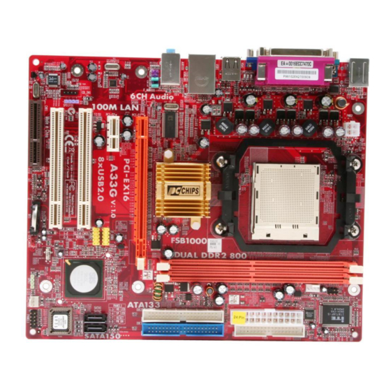
Page 9: Motherboard Components
Motherboard User’s Guide Motherboard Components ITEM LABEL COMPONENTS Socket AM2 for AMD Athlon 64/Athlon CPU Socket 64 X2 Dual-Core/Athlon 64 FX CPUs DDRII1~2 240-pin DDR2 SDRAM sockets Infrared header CPU_FAN1 CPU Fan connector(4 PIN) PWR1 Standard 24-Pin ATX Pow er connector... -
Page 10: I/O Ports
Microphone. Installing the Processor This motherboard has a socket AM2 processor socket. When choosing a processor, consider the performance requirements of the system. Performance is based on the processor design, the clock speed and system bus frequency of the processor, and... -
Page 11: Installing Memory Modules
The form and size of fan/heatsink may also vary. Installing Memory Modules This motherboard accommodates two 240-pin DIMM sockets (Dual Inline Memory Module) for unbuffered DDR2 800/667/533/400 memory modules (Double Data Rate SDRAM), and maximum 16 GB installed memory. - Page 12 Chapter 2: Motherboard Installation Over its predecessor, DDR2-SDRAM offers greater bandwidth and density in a smaller package along with a reduction in power consumption. In addition, DDR2- SDRAM offers new features and functions that enable a higher clock rate and data rate operations of 400 MHz, 533 MHz 667 MHz and 800 MHz.
-
Page 13: Jumper Settings
CMOS memory if the settings in the Setup Utility are incorrect and prevent your motherboard from operating. To clear the CMOS memory, disconnect all the power cables from the motherboard and then move the jumper cap into the CLEAR setting for a few seconds. -
Page 14: Install The Motherboard
Chapter 2: Motherboard Installation Install The Motherboard Install the motherboard in a system chassis (case). The board is a Micro ATX size motherboard. You can install this motherboard in an ATX case. Make sure your case has an I/O cover plate matching the ports on this motherboard. -
Page 15: Connecting Optional Devices
Connecting Optional Devices Refer to the following for information on connecting the motherboard’s optional devices: SPK1: Speaker Header Connect the cable from the PC speaker to the SPK1 header on the motherboard. Signal SPKR F_AUDIO1: Front Panel Audio Header This header allows the user to install auxiliary front-oriented microphone and line- out ports for easier access. - Page 16 Chapter 2: Motherboard Installation F_USB1~2: Front Panel USB Headers The motherboard has USB ports installed on the rear edge I/O port array. Addition- ally, some computer cases have USB ports at the front of the case. If you have this kind of case, use auxiliary USB headers F_USB1~2 to connect the front-mounted ports to the motherboard.
-
Page 17: Install Other Devices
Install and connect any other devices in the system following the steps below. Floppy Disk Drive The motherboard ships with a floppy disk drive cable that can support one or two drives. Drives can be 3.5" or 5.25" wide, with capacities of 360K, 720K, 1.2MB, 1.44MB, or 2.88MB. - Page 18 If you want to install more IDE devices, you can purchase a second IDE cable and connect one or two devices to the Secondary IDE channel connector IDE2 on the motherboard. If you have two devices on the cable, one must be Master and one must be Slave.
-
Page 19: Expansion Slots
Motherboard User’s Guide Here is a list of CD_IN1 pin assignments. Signal CD IN L CD IN R Expansion Slots This motherboard has one PCI Express x16, one PCI Express x1, one CNR and two 32-bit PCI slots. - Page 20 Chapter 2: Motherboard Installation Follow the steps below to install an PCI Express x16/ PCI Express x1/CNR/PCI expansion card. 1. Locate the PCI Express x16, PCI Express x1, CNR or PCI slots on the mainboard. 2. Remove the blanking plate of the slot from the system chassis.
-
Page 21: Chapter 3 Bios Setup Utility
You can run the setup utility and manually change the configuration. You might need to do this to configure some hardware installed in or connected to the motherboard, such as the CPU, system memory, disk drives, etc. Running the Setup Utility Every time you start your computer, a message appears on the screen before the operating system loading that prompts you to “Hit <DEL>if you want to run... -
Page 22: Standard Cmos Setup Page
Chapter 3: BIOS Setup Utility Some options on the main menu page lead to tables of items with installed values that you can use cursor arrow keys to highlight one item, and press PgUp and PgDn keys to cycle through alternative values of that item. The other options on the main menu page lead to dialog boxes requiring your answer OK or Cancel by selecting the [OK] or [Cancel] key. -
Page 23: Advanced Setup Page
Motherboard User’s Guide Advanced Setup Page This page sets up more advanced information about your system. Handle this page with caution. Any changes can affect the operation of your computer. CMOS Setup Utility – Copyright (C) 1985-2005, American Megatrends, Inc. -
Page 24: Features Setup Page
Chapter 3: BIOS Setup Utility Spread Spectrum If you enable spread spertrum, it can significantly reduce the EMI (Electro- Magnetic interface) generated by the system. Features Setup Page This page sets up some parameters for peripheral devices connected to the system. - Page 25 LAN while starting the system. OnBoard USB Function Enable this item if you plan to use the USB ports on this motherboard. USB Function For DOS Enable this item if you plan to use the USB ports on this motherboard in a DOS environment.
-
Page 26: Power Management Setup Page
Chapter 3: BIOS Setup Utility Power Management Setup Page This page sets some parameters for system power management operation. CMOS Setup Utility – Copyright (C) 1985-2005, American Megatrends, Inc. Help Item ACPI Aware O/S Power Management Enabled Enable /Disable Suspend mode ACPI support for Suspend Time Out Disabled... -
Page 27: Pci/Plug And Play Setup Page
Motherboard User’s Guide LAN/Ring Power On The system can be turned off with a software command. If you enable this item, the system can automatically resume if there is an incoming call on the Modem/ Ring, or traffic on the network adapter. You must use an ATX power supply in order to use this feature. -
Page 28: Bios Security Features Setup Page
Chapter 3: BIOS Setup Utility BIOS Security Features Setup Page This page helps you install or change a password. CMOS Setup Utility – Copyright (C) 1985-2005, American Megatrends, Inc. BIOS Security Features Help Item Security Settings Install or Change the Supervisor Password : Not Installed password. -
Page 29: Hardware Monitor Page
Motherboard User’s Guide CPU Type This item shows the type of the CPU installed in your system. CPU OVERCLOCK This item decides the CPU over-clocking function installed in your system. If the over-clocking fails, please turn off the system power. And then, hold the PageUp key (similar to the Clear CMOS function) and turn on the power, the BIOS will recover the safe default. -
Page 30: Load Optimal Defaults
Chapter 3: BIOS Setup Utility FANs & Voltage Measurements These items indicate cooling fan speeds in RPM and the various system voltage measurements. CPU/SYS FAN Speed This item displays CPU/ system speed measurement. CPU/System Temperature This item displays CPU/ system temperature measurements. Load Optimal Defaults This option opens a dialog box to ask if you are sure to install optimized defaults or not. -
Page 31: Chapter 4 Software & Applications
Setup screen automatically pops out, and then you can go on the auto-installing or manual installation depending on your operating system. If your operating system is Windows 2000/XP, it will automatically install all the drivers and utilities for your motherboard. Installing Support Software Insert the support CD-ROM disc in the CD-ROM drive. - Page 32 Chapter 4: Software & Applications contents of the disc with the Windows file browsing interface. The Exit button closes the Auto Setup window. To run the program again, reinsert the CD-ROM disc in the drive; or click the CD-ROM driver from the Windows Explorer, and click the Setup icon.
-
Page 33: Bundled Software Installation
This utility lets you erase the system BIOS stored on a Flash Memory chip on the motherboard, and lets you copy an updated version of the BIOS to the chip. Proceed with caution when using this program. If you erase the current BIOS and fail to write a new BIOS, or write a new BIOS that is incorrect, your system will malfunction.
Need help?
Do you have a question about the Motherboard and is the answer not in the manual?
Questions and answers