Table of Contents
Advertisement
Safe Operation Practices • Set-Up • Operation • Maintenance • Service • Troubleshooting • Warranty
O
'
M
peratOr
s
anual
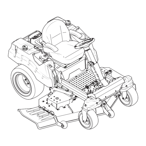
Z-Force SZ Commercial Zero-Turn Tractor
WARNING
READ AND FOLLOW ALL SAFETY RULES AND INSTRUCTIONS IN THIS MANUAL
BEFORE ATTEMPTING TO OPERATE THIS MACHINE.
FAILURE TO COMPLY WITH THESE INSTRUCTIONS MAY RESULT IN PERSONAL INJURY.
CUB CADET LLC, P.O. BOX 361131 CLEVELAND, OHIO 44136-0019
Printed In USA
Form No. 769-09409
(November 18, 2013)
Advertisement
Table of Contents

Related Manuals for Cub Cadet Z-Force SZ


Summary of Contents for Cub Cadet Z-Force SZ
- Page 1 READ AND FOLLOW ALL SAFETY RULES AND INSTRUCTIONS IN THIS MANUAL BEFORE ATTEMPTING TO OPERATE THIS MACHINE. FAILURE TO COMPLY WITH THESE INSTRUCTIONS MAY RESULT IN PERSONAL INJURY. CUB CADET LLC, P.O. BOX 361131 CLEVELAND, OHIO 44136-0019 Printed In USA Form No. 769-09409...
-
Page 2: Table Of Contents
See How-to Maintenance and Parts Installation Videos at www.cubcadet.com/tutorials ◊ Call a Customer Support Representative at (800) 965-4CUB ◊ Locate your nearest Cub Cadet Dealer at (877) 282-8684 ◊ Write to Cub Cadet LLC • P.O. Box 361131 • Cleveland, OH • 44136-0019... -
Page 3: Safe Operation Practices
Important Safe Operation Practices WARNING! This symbol points out important safety instructions which, if not followed, could endanger the personal safety and/or property of yourself and others. Read and follow all instructions in this manual before attempting to operate this machine. Failure to comply with these instructions may result in personal injury. - Page 4 A missing or damaged discharge cover can cause blade If situations occur which are not covered in this manual, use contact or thrown object injuries. care and good judgment. Contact your customer service representative for assistance. Stop the blade(s) when crossing gravel drives, walks, or roads and while not cutting grass.
- Page 5 Children • The fore/aft single-locking adjustment tracks operate on roller-bearings for smooth and almost effortless operation. Tragic accidents can occur if the operator is not alert to the The lever for seat track actuation is near the right front presence of children. Children are often attracted to the corner of the seat bottom, and allows fore/aft adjustment machine and the mowing activity.
-
Page 6: Spark Arrestor
General Service Do not change the engine governor settings or over-speed the engine. The governor controls the maximum safe Never run an engine indoors or in a poorly ventilated area. operating speed of the engine. Engine exhaust contains carbon monoxide, an odorless, Maintain or replace safety and instruction labels, as and deadly gas. -
Page 7: Safety Symbols
Safety Symbols This page depicts and describes safety symbols that may appear on this product. Read, understand, and follow all instructions on the machine before attempting to assemble and operate. Symbol Description READ THE OPERATOR’S MANUAL(S) Read, understand, and follow all instructions in the manual(s) before attempting to assemble and operate WARNING—... - Page 8 2 — S ection peration racticeS...
-
Page 9: Assembly & Set-Up
Assembly & Set-Up Steering Wheel Column NOTE: This Operator’s Manual covers several models. Tractor features may vary by model. Not all features in this manual are The steering wheel column is tilted all the way back for shipping applicable to all tractor models and the tractor depicted may purposes. - Page 10 Install Operator’s Seat Lower Deck Discharge Chute Deflector To install the seat proceed as follows: WARNING! Never operate the mower deck without the chute deflector installed and in the NOTE: The seat is shipped with the seat switch and seat down position.
- Page 11 Transmission Oil Expansion Reservoir Steering Wheel Remove the hardware for attaching the steering wheel The transmission oil expansion reservoir is connected by hoses from beneath the steering wheel cap. Carefully pry off the to the RH and LH transmission assemblies, and is located behind steering wheel cover to remove the hardware.
- Page 12 Connecting the Battery Cables Install the Rear Hitch Bracket CALIFORNIA PROPOSITION 65 WARNING Remove the hex flange screws and flange lock nuts that secure the hitch bracket to the bumper. See Figure 3-10. Battery posts, terminals, and related accessories contain lead and lead compounds, chemicals known to the State of California to cause cancer and reproductive harm.
-
Page 13: Controls & Features
Controls & Features Forward Drive Pedal Brake Pedal Reverse Drive Pedal Steering Column Adjustment Lever Deck Lift Handle Deck Height Index Seat Adjustment Lever Throttle Control Choke Control LCD Service Minder & Hour Meter Cup Holder PTO Switch Ignition Switch Fuel Valve Fuel Tank Cap Fuel Tank Cap... -
Page 14: Brake Pedal
Deck Height Index Power Take-Off (PTO) Switch The deck height index consists of several holes The PTO switch is located on the RH console to located on the front of the RH console. Each hole the left of the hour meter/indicator panel. corresponds to a 1⁄... -
Page 15: Throttle Control
Throttle Control Low Oil The letters “LO” followed by the letters “OIL”, then followed by The throttle control is located on the RH console. When the meter’s accumulated time will indicate the tractor is low on set in a given position, a uniform engine speed will be oil. -
Page 16: Operation
Learn to operate this machine SAFELY. Do not risk protection of the operator. If the interlock system should ever INJURY or DEATH. Allow only those who have become malfunction, do not operate the tractor. Contact your Cub Cadet competent in its usage to operate this tractor. dealer. - Page 17 Cold Weather Starting The tension of the deck drive belts are maintained by a spring mechanism that adjusts for wear and When starting the engine at temperatures near or below freezing, stretch. ensure the correct viscosity motor oil is used in the engine and the Examine the belts for cuts, fraying, and excessive battery is fully charged.
-
Page 18: Driving The Tractor
Driving The Tractor To travel in reverse, check that the area behind is clear then slowly push down on the reverse drive pedal with the WARNING! Avoid sudden starts, excessive speed ball of your foot (NOT your heel) until the desired speed is and sudden stops. - Page 19 Mowing Deck Lift Lever To raise or lower the cutting deck, depress the button on the WARNING! Make certain the area to be mowed is end of the handle and push downward to lower the deck, or pull free of debris, sticks, stones, wire or other objects upward to raise the deck, then place it in the hole best suited for that can be thrown by the rotating blades.
-
Page 20: Maintenance & Adjustment
Maintenance & Adjustments Maintenance Schedule Before Every Every Every Every Prior Each use 10 Hours 25 Hours 50 Hours 100 Hours to Storing Check Engine Intake Screen/Cover Clean Transmission Cooling Slots Clean Battery Terminals Lube Front Wheels Clean Engine Cooling Fins Lube Front Deck Wheels NOTE: This Operator’s Manual covers several models. - Page 21 General Battery Information Move the tractor to an area within reach of the hose where the dispersal of wet grass clippings is acceptable to you. Disengage WARNING! the PTO, engage the parking brake and stop the engine. • Should battery acid accidentally splatter into Pull back the lock collar of the nozzle adapter and push the the eyes or onto the skin, rinse the affected area adapter onto one of the deck wash nozzles at either end of...
- Page 22 Using the Transmission Bypass Rods Hydrostatic Transmission If for any reason the tractor will not drive or you wish to move the Your zero turn tractor is equipped with dual integrated tractor, the two hydrostatic transmissions are equipped with a bypass hydrostatic pumps/transaxles that are sealed and are rod that will allow you to manually move the tractor short distances.
- Page 23 Tractor Storage Start the engine and allow to idle for a few minutes to ensure engine is operating properly. Change the engine oil and filter following the instructions Drive the tractor without a load to make certain all the provided in the engine manual packed with this manual. tractor systems are functioning properly.
- Page 24 Leveling the Deck (Front-To-Rear) Adjusting the Front Gauge Wheels NOTE: Check the tractor’s tire pressure before performing WARNING!: Keep hands and feet away from the any deck leveling adjustments. Refer to Tires for information discharge opening of the cutting deck. regarding tire pressure.
- Page 25 Off-Season Storage Removing the Riding Mower from Storage Check the engine oil. Riding Mower Storage Fully charge the battery, lower riding mower off blocks, If your riding mower is not going to be operated for an extended and inflate the tires to the recommended pressure. period of time (thirty days to approximately six months), the riding Remove the spark plugs and wipe them off.
-
Page 26: Service
If the electrical system does not function, check for a blown fuse. If you have a recurring problem with blown fuses, have the tractor’s electrical system checked by your Cub Cadet Service Dealer. Battery Hold-Down Bracket Relays and Switches There are several safety switches in the electrical system. -
Page 27: Rolling Belt Off Pto Pulley
Releasing Belt Tension with the Idler Pulley Rolling the Belt off the PTO Pulley Using the deck lift handle, raise the deck to the position Using the deck lift handle, raise the deck to the position that that provides the most horizontal run of the belt between provides the most horizontal run of the belt between the deck the deck idler pulleys and the PTO pulley on the bottom of idler pulleys and the PTO pulley on the bottom of the engine. -
Page 28: Deck Installation
Locate the LH and RH deck release pins on each side of the Make certain the belt is in the spindle pulleys of the deck, deck. Pull the release pins outward and release the deck and that the backside of the belt is against both the fixed from the LH and RH deck lift arms. - Page 29 Changing the Transmission Drive Belt Several components must be removed and special tools used in order to change the tractor’s transmission drive belt. See your Cub Cadet dealer to have the transmission drive belt replaced. Tractor Creeping Figure 7-9 Creeping is the slight forward or backward movement of the...
-
Page 30: Troubleshooting
Troubleshooting Problem Cause Remedy Excessive vibration 1. Cutting blade loose or unbalanced. 1. Tighten blade and spindle. 2. Damaged or bent cutting blade. 2. Replace blade. Uneven cut 1. Deck not leveled properly. 1. Perform side-to-side deck adjustment. 2. Dull blade. 2. -
Page 31: Parts List
Replacement Parts Component Part Number and Description 954-05012 Deck Belt, 48” Deck 954-05013 Deck Belt, 54” Deck 954-05015 Deck Belt, 60” Deck 954-04317A Drive Belt 942-04417 Blades, 48” 02005017-X Xtreme Blades, 48” 942-04416 Blades, 54” 02005018-X Xtreme Blades, 54” 942-04415 Blades, 60”... - Page 32 Component Part Number and Description 725-1744A Ignition Key 631-05176 Discharge Chute Assembly 634-04295 Rear Wheel Assembly 634-04629 Front Wheel Assembly 9 — R ection eplacement aRtS...
-
Page 33: Attachments & Accessories
Attachments & Accessories Part No. Part 19A70018100 Light Kit 59A30045150 FAB Power Assist Bagger OEM-190-784 Wheel Weights 19A70037100 48” Mulch kit 19A70039100 60” Mulch Kit 19A70044100 58” Snow Blade 490-241-0025 Tire Chains 490-850-0008 Oil Siphon 490-850-0005 Blade Removal Tool 490-325-0020 Tire Sealant 490-900-0045 Oil Filter Wrench... - Page 34 FEDERAL and/or CALIFORNIA EMISSION CONTROL WARRANTY STATEMENT YOUR WARRANTY RIGHTS AND OBLIGATIONS MTD Consumer Group Inc, the United States Environmental Protection Agency (EPA), and for those products certified for sale in the state of California, the California Air Resources Board (CARB) are pleased to explain the evaporative emission control system (ECS) warranty on your 2013-2014 small off-road equipment (outdoor equipment).
- Page 35 WARRANTED PARTS: The repair or replacement of any warranted part otherwise eligible for warranty coverage may be excluded from such warranty coverage if MTD Consumer Group Inc demonstrates that the outdoor equipment has been abused, neglected, or improperly maintained, and that such abuse, neglect, or improper maintenance was the direct cause of the need for repair or replacement of the part.
-
Page 36: Warranties
Contact MTD Products Limited, Kitchener, ON N2G 4J1, call 1-800- The limited warranty set forth below is given by Cub Cadet LLC with 668-1238 or log on to our website at www.mtdcanada.com. respect to new merchandise purchased or leased and used in the...